
Related Manuals for Comelit 6750W


Summary of Contents for Comelit 6750W
- Page 1 TECHNICAL MANUAL Handsfree entry phone Mini Art. 6750W, 6751W Passion.Technology.Design.
-
Page 2: Table Of Contents
• any purpose other than the intended use, • failure to observe the indications and warnings contained in this Manual / Instruction sheet. Comelit Group S.p.A. reserves the right to change the information provided in this Manual / Instruction Sheet at any time and without prior notice. -
Page 3: Description
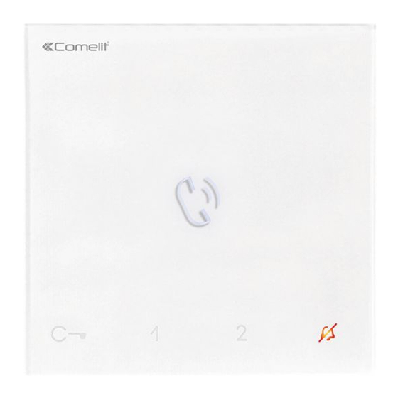
Description Art. 6750W Mini series hands-free door entry phone with full-duplex audio and integrated magnetic induction amplification system. Allows speaker volume adjustment and call volume adjustment, with ringtones which can be customised by choosing one of several different melodies. Equipped with 5 sensitive touch buttons for audio control, lock-release, actuator, switchboard call and privacy function, as well as door status indicator LEDs. -
Page 4: Art. 6751W
Art. 6751W Mini series hands-free door-entry phone with full-duplex audio. Allows speaker volume adjustment and call volume adjustment, with ringtones which can be customised by choosing one of several different melodies. Equipped with 5 sensitive touch buttons for audio control, lock-release, actuator, switchboard call and privacy function, as well as door status indicator LEDs. Manages floor door calls as standard. -
Page 5: Legend: Buttons And Indicator Leds
Legend: buttons and indicator LEDs f Press the desired button once to activate the associated function Wait for approximately 1 sec. before pressing the same button again. Pressing the same button several times in quick succession will cancel the command. Description of buttons Indicator LED description Audio activation... -
Page 6: Technical Specifications
Technical specifications Art. 6750W Art. 6751W GENERAL DATA Height (mm) Width (mm) Depth (mm) HARDWARE CHARACTERISTICS Removable terminals SETTINGS Loudspeaker volume control Ringtone volume adjustment MAIN FEATURES Audio/video system Surface mounting Desk base mounting Hands-free function Induction loop function Colour... -
Page 7: Surface Mounting
Surface mounting optional CLACK! » REMOVAL... - Page 8 Terminal removal Terminal installation...
-
Page 9: Connections
Connections Connection to the video entry riser and the floor door call button 6750W VIDEO ENTRY SYSTEM RISER 1214/2C FLOOR DOOR CALL 1209 / 1210 / 1210A /4888C Branched connection to the video entry system riser from the door entry monitor... -
Page 10: Button Configuration
Button configuration By default the buttons control the functions in row A (“Standard configuration” table). It is possible to change the default configuration of the buttons by changing the positions of S2 DIP-switches 1-2-3-4 on the rear of the door-entry phone to one of the combinations (B-P) suggested in the table. All the buttons will change function. Basic configuration BUTTON PROGRAMMING DIP-switch S2... -
Page 11: General Intercom Call: Button Programming
Advanced configuration If the standard configuration settings (A-P) do not reflect requirements, the buttons can be programmed differently by carrying out the steps below. After programming, set S2 DIP-switches 1-2-3-4 (PROG) to ON. With these DIP-switch settings, the buttons manage the programmed functions. The buttons that are NOT programmed control the functions in row A (table “Basic configuration"... -
Page 12: Selective Intercom Address
Selective intercom address TABLE B Code S1 DIP-switch ON Code S1 DIP-switch ON Code S1 DIP-switch ON Assigning a selective address (Steps only need to be carried out for “Intercom call to selective address” programming) Take note of the S1: Set an address. S2: Set the DIP-switches as S1, S2 settings and (Table B) -
Page 13: Coded Actuator: Button Programming
Coded actuator: button programming 1. Take note of the S1 DIP-switch settings. 2. To enter programming mode, set S2 DIP-switch 6 to ON. » the LED flashes Refer to the table to identify a DIP-switch combination in which the actuator function (ACT) “Basic configuration"... -
Page 14: Programming Range
Programming range Take note of the S2, S1 settings and restore on completion of programming f Carry out steps 1 to 4 Range minimum address set code. “Addressing table" Range maximum address Enable range Disable range Deleting the range 2 sec... -
Page 15: Changing The Ringtone
Changing the ringtone 1. Press and hold for 6 sec. » a confirmation tone is emitted » the LED flashes √ the procedure can only take place while the system is in standby; otherwise the LED will flash 4 times to inform the user that the system is busy 2 Press and release once (1 confirmation tone sounds) to change the ringtone for calls from the external entrance panel. -
Page 16: Addressing Table
2,3,5,8 3,5,6,8 2,5,7,8 5,6,7,8 *240 System performance and layouts Art. 6750W For further information of system performance and to view installation layouts, click on the system type that best meets your requirements: • Simplebus2 audio/video with 1210/1210A • Simplebus2 audio/video with 4888C Art. - Page 17 C E R T I F I E D M A N A G E M E N T S Y S T E M S w w w . c o m e l i t g r o u p . c o m Via Don Arrigoni, 5 - 24020 Rovetta (BG) - Italy...