
Related Manuals for Samsung MIM-D01AN


Summary of Contents for Samsung MIM-D01AN
-
Page 1: Air Conditioner
DMS2.5 (Data Management Server2.5) MIM-D01AN MIM-D01AUN BACnet Gateway MIM-B17BN MIM-B17BUN LonWorks Gateway MIM-B18BN MIM-B18BUN Air Conditioner user manual imagine the possibilities Thank you for purchasing this Samsung product. - Page 2 Safety Precautions English Before using the DMS2.5, BACnet Gateway, LonWorks Gateway, read carefully these instructions. After reading the instructions, keep this user's manual in a handy and safe place. If a user is changed, you must hand over the manuals. Never attempt to install the air conditioning system or to move the product by yourself.
- Page 3 Contents ............4 ENERAL ESCRIPTION ............6 IEWING THE ARTS ..............8 EFORE ............. 10 UNCTION DMS2.5 ............14 TARTING ..........20 ONTROL AND ONITORING ............67 ANAGEMENT ..............72 CHEDULE EHP P ......85 OWER ONSUMPTION NSPECTION ........96 ONTROL OGIC ANAGEMENT...
-
Page 4: G Eneral D Escription
General Description Introduction of DMS2.5 (Data Management Server2.5) The DMS2.5 is an Ethernet based device for central management of Samsung system air- conditioners. It operates 24 hours without a separate management (PC). Advantages of DMS2.5 System The DMS2.5 provides the following advantages: Everyday Device–The DMS2.5 is operational all year long 24 hours. - Page 5 Terms DMS2.5: The abbreviation of Data Management Server2.5. Upper Controller: S-NET 3, RMS and DMS2.5 which allows controlling by accessing to a web page. OnOff Controller: A device that controls 16 groups of the DVM air conditioner. A central control device of a DVM system which is located between a DMS2.5 and an outdoor unit.
-
Page 6: Viewing The Part
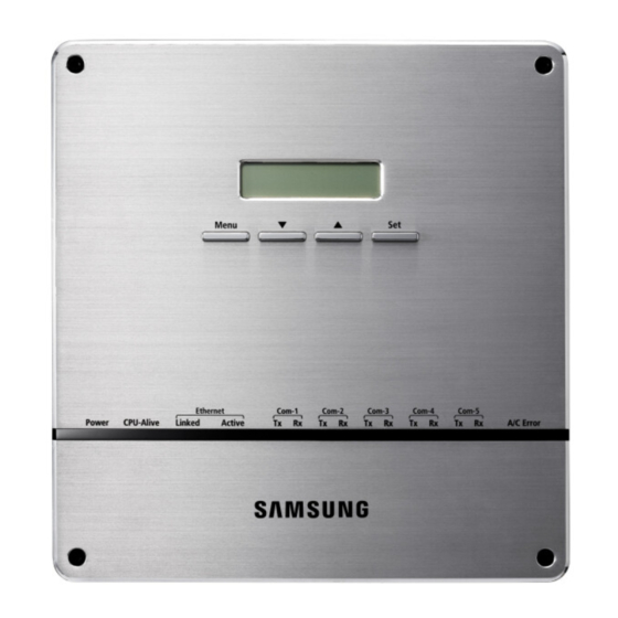
Viewing the Parts Front View Name Description LCD Display Display current time/ Check menu Menu button Access to main menu Select the function you want and set detailed functions in ▼/▲ button main menu Check the function you want from main menu Set button and select it Unfasten 2 screws on the bottom and separate the bottom... - Page 7 Bottom View Separate bottom cover by unfastening 2 screws on the bottom. DI Terminal2 DO Terminal1 Connect Digital Input Connect Digital Output - Channel 6~Channel10 - Channel 1~Channel 5 DO Terminal 2 DI Terminal1 Connect Digital Output Connect Digital Input - Channel 6~Channel 8 - Channel 1~Channel 5 Reserved...
-
Page 8: Before Use
Before Use System Configuration S-NET 3 Web Client TCP/IP DMS2.5 Internet Touch PM 05:45 Centralized OnOff controller controller R5 485 RMS Senter Outdoor Unit SIM/PIM Power meter Max 256 Indoor units (DVM Series) Connecting outdoor unit and DMS2.5 - You can control up to 80 outdoor units and 256 indoor units by using DMS2.5. ※... - Page 9 [System environment setting]. - Private IP range: 10.0.0.0 ~ 10.255.255.255, 172.16.0.0 ~ 172.31.255.255, 192.168.0.0 ~ 192.168.255.255 Use this product only in a separate dedicated network. Samsung electronics is not liable for any problems caused by connecting it to the Internet or an intranet.
-
Page 10: Main Function
When an error occurs, it sends trouble history to e-mail saved in DMS2.5. Some functions available on DMS2.5 web page may not be functional at BACnet Gateway and Lonworks Gateway. For detailed function, refer to the installation manual or contact Samsung Electronics. Device Type Indoor unit communication error Indoor Unit... - Page 11 Set and Run Schedule The schedule function of the DMS2.5 can be set through the Web or using the upper level controller. 1day/Everyday/Every week schedules can be set. Each schedule can be used selectively by using the run schedule/stop schedule order. At most 256 schedules can be set.
- Page 12 Main Function (Continued) Save Integrated Power Distribution Data The DMS2.5 calculates and distributes the power consumed by each indoor unit by receiving the total power usage from the watt-hour meter interface modules (SIM/PIM) and taking into account the operation status of the indoor units. The DMS2.5 saves at most 1 year of data.
-
Page 13: Time Segmentation
Time Segmentation Time segmentation is used to divide 24 hours into different sections and to distribute power according to each section. This function is used when the power consumption fee is different according to different time slots or when a building is charged differently depending on the consumption time. -
Page 14: S Tarting Dms2.5
Starting DMS2.5 Starting DMS2.5 Current time setting Set the current time of DMS2.5 system. “2016/01/01 01:01:01” is factory setting. Set the current time as DMS2.5 system time. You can set DMS2.5 time in [System Settings] [System environment setting] (Refer to page 129~130) If DMS2.5 time does not set as the current time, DMS2.5 may cause malfunction when using Schedule or control logic management. - Page 15 Run internet explorer on your computer. Enter IP address (https://192.168.0.100) on the address bar, and then press [ENTER]. If it is the first access to DMS2.5, “Install Microsoft Silverlight” message will be displayed. - The message will not appear if Microsoft Silverlight have already installed. If the message window and login screen does not appear, check PC setting status.
- Page 16 Starting DMS2.5 (Continued) B. Select ‘Trusted Root Certification Authorities’ and click ‘Import’. C. Click ‘Next’. D. Select ‘Browse’ and find DMS2.5 certificate, and click ‘Next’. DMS2.5 certificate can be downloaded from [System environment setting].
- Page 17 E. Select ‘Place all certificates in following drive’ and click ‘Next’. F. Click ‘Finish’, and click ‘Yes’ when security warning appears. Click [Run] and continue installation. Access to DMS2.5 again after installation.
- Page 18 Starting DMS2.5 (Continued) Enter ID and password when DMS2.5 main web page appears. Then click [LOGIN]. The default DMS2.5 user ID is 'admin' and password is 'ac0530'. Depending on authorization settings which set by the administrator, access to some functions may be restricted. To edit user authorization, refer to [System Settings] [User authorization management].
- Page 19 Logged-in User with No Authorization When the screen above appears, ask for manager. Depending on control authorization setting, there can be a user who does not have control authorization. Above screen will appear when the logged-in user does not have control authorization.
- Page 20 Control and Monitoring Devices controlled and monitored by DMS2.5 Remote controller Remote controller Type Display Type Display (Controlling range) (Controlling range) Indoor unit (Digital display Input) icon display icon (Digital display Output) icon display icon Hydro Unit HT, display display icon icon ERV PLUS FCU Kit...
- Page 21 In this case, vertical or fixed flow will be displayed depending on indoor unit’s basic operation specification. Some functions available on DMS2.5 web page may not be functional at BACnet Gateway and LonWorks Gateway. For detailed function, refer to the installation manual or contact Samsung Electronics.
- Page 22 Control and Monitoring (Continued) Controlling an Indoor Unit Status display window Click [Control and Monitoring] when DMS2.5 web page menu screen appears. [Control and Monitoring] screen will appear when you log-in to DMS2.5 web page. Select an indoor unit to control. Check the indoor unit status through status display window.
- Page 23 Select the operation mode. You can select Auto, Cool, Dry, Fan and Heat operation mode. Click [ ][ ] to set the desired temperature. Each time you press the buttons, the temperature will be adjusted by 1 or 0.1°C (or by 1°F). If Auto/Cool/Dry mode is in operation, you can adjust the desired temperature in the range of 18°C(64°F)~30°C(86°F).
- Page 24 Control and Monitoring (Continued) Select the air flow. You can select Vertical, Horizontal, All and None air flow direction. Set remote controller settings. You can select Enable RC, Disable RC, and Cond. RC. When selecting [Disable RC], indoor unit control by wired/wireless remote controller and indoor unit panel is not possible.
- Page 25 Select MDS setting . You can set MDS(Motion Detection Sensor) through button activation / non activation. Set cooling/heating discharge temperature by clicking [ ] and [ ]. When the indoor unit is in Cool mode, you can adjust cooling discharge temperature and when the indoor unit is in Heat mode, you can adjust the heating discharge temperature.
- Page 26 Control and Monitoring (Continued) Indoor Unit Operation Mode Limit Status display window You can monitor the operation status of all indoor units or have individual or whole control of the indoor units. Click [Control and Monitoring] when DMS2.5 web page menu screen appears.
- Page 27 Set operation mode limit. You can select [coolonly (Cool)], [heatonly (Heat)], and [No limits]. - No limits : You can use cool mode and heat mode with no limits. Note Operation mode limits setting is not available in ERV and DVM CHILLER. If you set the operation mode limit, DMS2.5 will automatically change the operation mode limit setting of all the indoor units connected to same outdoor unit.
- Page 28 Control and Monitoring (Continued) Setting Lower/Upper Temperature Limit of an Indoor Unit Status display window You can monitor the operation status of all indoor units, and control the indoor units as a whole, or as individual units. Click [Control and Monitoring] when DMS2.5 web page menu screen appears.
- Page 29 Set upper temperature limit by pressing [ ] and [ ]. Click 'Heat upper limit' to apply the upper temperature limit setting. Upper temperature limit can be set in the range of 16°C(61°F)~30°C(86°F). When an indoor unit is operating in Heat mode and the upper temperature limit is applied, you cannot set the desired temperature higher than the upper temperature limit.
- Page 30 Control and Monitoring (Continued) Monitoring AHU Operation Status Status display window You can monitor the operation status of AHU, and control AHU as a whole, or as individual units. Click [Control and Monitoring] when DMS2.5 web page menu screen appears. [Control and Monitoring] screen will appear when you log-in to DMS2.5 web page.
- Page 31 Monitoring Fresh duct operation status Status display window You can monitor the operation status of Fresh duct, and control the Fresh duct as a whole, or as individual units. Click [Control and Monitoring] when DMS2.5 web page menu screen appear. [Control and Monitoring] screen will appear when you log-in to DMS2.5 web page.
- Page 32 Control and Monitoring (Continued) Controlling a Fresh duct Click [Control and Monitoring] when DMS2.5 web page menu screen appear. [Control and Monitoring] screen will appear when you log-in to DMS web page. Check the current status of a Fresh duct. Check the status of a Fresh duct through the status display window.
- Page 33 Note Refer to the ‘OnOff controller’ for Fresh duct control. (Refer to page 22~25) The fan speed of a Fresh duct is fixed as ‘High’ . Setting air flow direction of a Fresh duct is not available. Refer to the ‘Indoor unit operation mode limit’ for Fresh duct operation mode limit.
- Page 34 Control and Monitoring (Continued) Monitoring ERV Operation Status Status display window You can monitor the operation status of ERV, and control the ERV as a whole, or as individual units. Click [Control and Monitoring] when DMS2.5 web page menu screen appears. [Control and Monitoring] screen will appear when you log-in to DMS2.5 web page.
- Page 35 Controlling ERV You can monitor the operation status of ERV, and control the ERV as a whole, or as individual units. Click [Control and Monitoring] when DMS2.5 web page menu screen appears. [Control and Monitoring] screen will appear when you log-in to DMS2.5 web page.
- Page 36 Control and Monitoring (Continued) Select the operation mode. You can select Auto, HeatEx, By pass and Sleep. Select the fan speed. You can select Low, High and Turbo. Fan speed is set to Low in Sleep mode. Set remote controller settings. You can select Enable RC, Disable RC, and Cond.
- Page 37 Monitoring ERV PLUS operation status Status display window You can monitor the operation status of ERV PLUS, and control the ERV PLUS as a whole, or as individual units. Click [Control and Monitoring] when DMS2.5 web page menu screen appears. [Control and Monitoring] screen will appear when you log-in to DMS2.5 web page.
- Page 38 Control and Monitoring (Continued) Controlling ERV PLUS Click [Control and Monitoring] when DMS2.5 web page menu screen appear. [Control and Monitoring] screen will appear when you log-in to DMS2.5 web page. Select ERV PLUS to control. Check the status of ERV PLUS through the status display window. When the selected ERV PLUS is switched on, the remote controller panel will be automatically activated.
- Page 39 Controlling Hydro unit Click [Control and Monitoring] when DMS2.5 web page menu screen appear. [Control and Monitoring] screen will appear when you log-in to DMS2.5 web page. Select a Hydro unit to control. When the selected Hydro unit is switched on, the remote controller panel will be automatically activated.
- Page 40 Control and Monitoring (Continued) Icon will be activated when either Thermostat 1 or Thermostat 2 is on. Icon will be activated when the Outing mode is on. Type of temperature control will be displayed. Control and monitoring status of current temperature, desired temperature, operation mode, Heat upper limit and Cool lower limit will be changed depending on the type of temperature control.
- Page 41 Select Heat upper limit and Cool lower limit by clicking [ ] [ ]. Select [coolonly] or [heatonly] button. Click the button to turn on/off the power for direct heat water. You can turn on the power for direct hot water only when the operation mode is on Auto or Heat mode.
- Page 42 Control and Monitoring (Continued) Controlling Hydro Unit HT Click [Control and Monitoring] when DMS2.5 web page menu screen appear. [Control and Monitoring] screen will appear when you log-in to DMS2.5 web page. Select a Hydro Unit HT to control. When the selected Hydro Unit HT is switched on, the remote controller panel will be automatically activated.
- Page 43 Icon will be activated when either Thermostat 1 or Thermostat 2 is on. Icon will be activated when the Outing mode is on. Type of temperature control will be displayed. Control and monitoring status of current temperature, desired temperature, operation mode, Heat upper limit and Cool lower limit will be changed depending on the type of temperature control.
- Page 44 Control and Monitoring (Continued) Select Heat upper limit by clicking [ ] [ ]. To select exclusive operation mode, select [heatonly] or [No limits]. Click the button to turn on/off the power for direct heat water. You can turn on the power for direct hot water only when the operation mode is on Auto or Heat mode.
- Page 45 Monitoring DMS DI/DO Operation Status Click [Control and Monitoring] when DMS2.5 web page menu screen appears. [Control and Monitoring] screen will appear when you log-in to DMS2.5 web page. Check the current status of DI and DO device. Monitor the device through the control panel. Note Entering OnOff becomes impossible for DI device.
- Page 46 Control and Monitoring (Continued) Controlling DMS DO Click [Control and Monitoring] when DMS2.5 web page menu screen appears. [Control and Monitoring] screen will appear when you log-in to DMS2.5 web page. Select DO device to control when control and monitoring screen appears. Check the status of DI or DO device.
- Page 47 Controlling FCU Kit Click [Control and Monitoring] when DMS2.5 web page menu screen appears. [Control and Monitoring] screen will appear when you log-in to DMS2.5 web page. Select FCU to control when control and monitoring screen appears. Check the status of an indoor unit through status display window. When the selected indoor units are switched on, the remote controller panel will be automatically activated.
- Page 48 Control and Monitoring (Continued) Note Refer to the ‘Controlling an indoor units’ steps for FCU Kit control. (Refer to page 22~25) Refer to the ‘Indoor unit operation mode limit’ for FCU Kit operation mode limit. (Refer to page 26~27) Refer to ‘Setting Lower/Upper Temperature Limit of an Indoor Unit’...
- Page 49 Controlling DVM CHILLER Click [Control and Monitoring] when DMS2.5 web page menu screen appears. [Control and Monitoring] screen will appear when you log-in to DMS2.5 web page. Select DVM CHILLER to control when control and monitoring screen appears. Check the status of an indoor unit through status display window. When the selected indoor units are switched on, the remote controller panel will be automatically activated.
- Page 50 Control and Monitoring (Continued) Select the operation mode. You can select Cool, Cool Storage, Heat, and Hot Water mode. Select the operation pattern. You can select Standard, Rotation, Efficiency pattern. Select Water Law setting. You can enable/disable button to select Water Law. You cannot adjust the desired temperature in Water Law.
- Page 51 Monitoring the selected multiple devices operation status Status display window You can monitor the operation status of other type devices, and control other type devices as a whole, or as individual units. Click [Control and Monitoring] when DMS2.5 web page menu screen appears. [Control and Monitoring] screen will appear when you log-in to DMS2.5 web page.
- Page 52 Control and Monitoring (Continued) Controlling the selected multiple devices Click [Control and Monitoring] when DMS2.5 web page menu screen appears. [Control and Monitoring] screen will appear when you log-in to DMS2.5 web page. Check the status of the selected devices. Check the status of an indoor unit through status display window.
- Page 53 Select the desired temperature by clicking [ ][ ]. Each time you press the buttons, the temperature will be adjusted by 1 or 0.1°C (or by 1°F). If Auto/Cool/Dry mode is in operation, you can adjust the desired temperature in the range of 18°C(64°F)~30°C(86°F).
- Page 54 Control and Monitoring (Continued) Select the ERV operation mode. You can select Auto, Heat Ex, By pass and Sleep mode. Select the fan speed. You can select Low, high and Turbo. If Sleep mode is in operation, the fan speed will be set as Low fan speed.
- Page 55 Checking the Installation Information You can check the installation status of currently connected device. Click [Control and Monitoring] when DMS2.5 web page menu screen appears. [Control and Monitoring] screen will appear when you log-in to DMS2.5 web page. Click ‘Install.Info’. tab at the bottom left of the screen. Check installation status of currently connected device in the installation information tab.
- Page 56 Control and Monitoring (Continued) View the Control History & Power Consumption You can select a device and view control history and power consumption information. Click [Control and Monitoring] when DMS2.5 web page menu screen appears. [Control and Monitoring] screen will appear when you log-in to DMS2.5 web page.
- Page 57 When data reception is completed from DMS2.5, check control history and power consumption of selected device. Note In ‘Control history’ , you can check power control and remote controller usage status. Operation mode, desired temperature, air flow and fan speed control shows you the controlled time and type of control only.
- Page 58 Control and Monitoring (Continued) Cycle Monitoring You can select an indoor unit and check cycle information. Click [Control and Monitoring] [Cycle Monitoring] when DMS2.5 web page menu screen appears. Click [Select]. DMS2.5 installation information will be displayed. Select a device to check cycle information. If you select OnOff controller, its subordinate outdoor unit which has the earliest address will be selected.
- Page 59 Indoor Unit Usage Restriction_Operation Limit You can set the operation of indoor unit as cooling only and heating only. Click [Control and Monitoring] [Indoor unit usage restriction] when DMS2.5 web page menu screen appears. Press [Edit] button. Set the limit mode. You can select 'Cool-only’, ‘Heat-only’...
- Page 60 Control and Monitoring (Continued) Set the control mode. Control mode is used for DMS2.5 to set either 'cool only' or 'heat only' mode to indoor and outdoor units. Note Mixed operation can occur even if you set limit mode. If the indoor unit with operation mode limit is in mixed operation, DMS2.5 will solve the problem automatically by controlling it in control mode.
- Page 61 Indoor Unit Usage Restriction_Temperature Limit in Cool/Heat mode You can set temperature lower/upper temperature limit in cool/heat mode. Click [Control and Monitoring] [Indoor unit usage restriction] when DMS2.5 web page menu screen appears. Press [Edit] button. Set the lower/upper temperature limit. You can set lower/upper temperature limit by selecting 'Enable'/'Disable'.
- Page 62 Control and Monitoring (Continued) Checking the Trouble History Click [Control and Monitoring] [Trouble history] when DMS2.5 web page menu screen appears. Check all the trouble history. You can check address, device type, occurrence time, resolution time, code number and status. You can check detailed information on trouble history by selecting the item in the list.
- Page 63 Checking the Trouble History by Date DMS2.5 saves maximum 1024 trouble histories. If the number of history exceeds 1024, DMS2.5 will delete the oldest history first. Click [Control and Monitoring] [Trouble history] when DMS2.5 web page menu screen appears. Enter the time period you want to check. Enter year/month/day in order.
- Page 64 Control and Monitoring (Continued) Deleting the Trouble History Click [Control and Monitoring] [Trouble history] when DMS2.5 web page menu screen appears. Select trouble history you want to delete. Click [Delete]. Click [OK] from the confirm window. Selected trouble history will be deleted.
-
Page 65: Outdoor Unit Control
Outdoor unit control Click [Control and Monitoring] [Outdoor unit control] when DMS2.5 web page menu screen appears. Click [Edit] and select the desired setting for Electric current control option, Heating capacity calibration and Cooling capacity calibration. Outdoor unit self-control: Outdoor unit controls the value itself. Manual: Outdoor will be controlled at value set by the user. - Page 66 Control and Monitoring (Continued) Checking the Operation Status You can check operation status of indoor unit which is controlled by DMS2.5. Click [Control and Monitoring] [Checking operation status] when DMS2.5 web page menu screen appears. Check the operation history. You can check the device type, occurrence time, control unit, control type, and controlled device address of indoor unit which is controlled by DMS2.5 and subordinate controller.
-
Page 67: Z One M Anagement
Zone Management Zone Setting & Edit – Individual/Group Initialization Click [Zone management] [Zone Setting & Edit] when DMS2.5 web page menu screen appears. Same screen will be displayed even if you click [Zone management] only. Initialize the indoor unit organization as individual by clicking [Individual]. Individual initialization reorganizes connected indoor unit based on installation address. - Page 68 Zone Management (Continued) Zone Setting & Edit – Setting the User Authorization Click [Zone management] [Zone Setting & Edit] when DMS2.5 web page menu screen appears. Same screen will be displayed even if you press [Zone management] only. Set user authorization for each zone. If the user has no authorization for the zone, controlling and monitoring of the zone is restricted.
- Page 69 Zone Setting & Edit – Zone Edit Click [Zone management] [Zone Setting & Edit] when DMS2.5 web page menu screen appears. Same screen will be displayed even if you press [Zone management] only. Click [Zone Edit]. Zone edit screen will be displayed.
- Page 70 Zone Management (Continued) Click [▼] to set viewing option of zone edit list. You can select from viewing by 'Name’, ‘Address’ and ‘Address & Name'. Edit item you want. Create in the Create a new zone on top of the selected zone. above Create in the Create a new zone under the selected zone.
- Page 71 Click [Remove disappeared] to remove all disappeared devices which were found after tracking. Change zone properties. You can select “General”, “AHU”, and “Group”. Mode Property name Description Remarks Virtual group which is managed by installation address, not by RMC General address The user can create and delete zone.
-
Page 72: S Chedule
Schedule Creating New schedule You can set, edit, delete and use the schedules for air conditioner control. Click [Schedule] [Schedule setting] when DMS2.5 web page menu screen appears. Click [New] in the schedule setting screen. Note It is not available to provide the schedule information to BMS system. - Page 73 To cancel the added exception date, select the exception date it( ) and click [Delete]. Maximum 365 exception dates can be saved.
- Page 74 Schedule (Continued) Click [Add] to select a device to apply. The list of all the connected devices will be displayed. You can register a schedule for DMS DO as well. You cannot select DVM CHILLER and other devices simultaneously. To cancel the selected device, select ( ) the device again and click [Delete].
- Page 75 Click [∨] to select repeat schedule you want and set an event. You can select 'Weekly', 'Everyday' and '1day'. However, the starting and end date should be same when you select '1day'. Enter 4 digits for OnOff time setting. Ex) 8:00 0800, 9:30 0930 Remote controller setting is as follows.
- Page 76 Schedule (Continued) Click [Save]. Set schedule information is saved in DMS2.5. Click [Cancel] to cancel schedule setting. Note If you select dry mode among basic modes, auto fan speed is only available. When the operation mode is ‘Auto’ , fan speed is always set to ‘Auto’...
- Page 77 Creating new schedule for EHS Click [Schedule] [Schedule setting] when DMS2.5 web page menu screen appears. Click [New EHS] in the schedule setting screen. Enter the schedule name when the schedule setting screen appears. Select schedule period you want by clicking calendar. If you select 'No limit' when setting end date, it means there is no period and it displays Dec 31st, 9999.
- Page 78 Schedule (Continued) To cancel the added exception date, select the exception date ( ) and click [Delete]. Maximum 365 exception dates can be saved.
- Page 79 Click [Add] to select a device to apply. The list of all the connected devices will be displayed. Select a device and click [OK]. You can only select one device. To cancel the selected device, select ( ) the device again and click [Delete].
- Page 80 Schedule (Continued) Click [∨] to select repeat schedule you want and set an event. You can select 'Weekly', 'Everyday' and '1day'. However, the starting and end date should be same when you select '1day'. Enter 4 digits to set the time for turning ON/OFF the EHS and the Hot water. Ex) 8:00 0800, 9:30 0930...
- Page 81 Click [Save]. Created schedule information will be saved in DMS2.5. Click [Cancel] to cancel schedule setting. Note Since Hydro unit HT does not support Cool mode, you should not add any schedules related to Cool mode. If the desired temperature is set when the operation mode is ‘None’...
- Page 82 Schedule (Continued) Editing Schedule Click [Schedule] [Schedule setting] when DMS2.5 web page menu screen appears. Select the schedule to edit. For the currently operating schedule, you can only check it. Click [Edit]. Edit schedule when the schedule edit screen appears. Editing schedule method is same as “Creating New Schedule”.
- Page 83 Deleting Schedule Click [Schedule] [Schedule setting] when DMS2.5 web page menu screen appears. Select the schedule to delete. Click [Delete]. Click [OK] in confirm window and selected schedule will be deleted. Deleting schedule is possible only when the schedule is in stop status. If you want to delete schedule which is currently applied, stop applying the schedule first.
- Page 84 Schedule (Continued) Checking Schedule Control History Click [Schedule] [Checking schedule control history] when DMS2.5 web page menu screen appears. Select a date to check and then click [Search]. Only executed schedules can be searched. You can check detailed setting by clicking the schedule name.
-
Page 85: I Nspection
EHP Power Consumption Inspection Checking Inspection Result (with SIM/PIM) You can check the operation history and power consumption saved in DMS for each indoor unit. Click [EHP Power Consumption Inspection] [Check inspection result] when DMS2.5 web page menu screen appears. Set date and search condition (power consumption/proportion/individual indoor unit by date) when inspection result screen appears. - Page 86 EHP Power Consumption Inspection (Continued) Checking Inspection Result (without SIM/PIM) Click [EHP Power Consumption Inspection] [Check inspection result] when DMS2.5 web page menu screen appears. Channel setting by indoor unit must be done in advance. Set date when inspection result screen appears. Select year/month/day in order.
- Page 87 Check the power consumption result of the selected period. Due to rounding the actual values, actual input value and result value may different to each other. If you want to save the consumption result for selected period as MS Excel file, click [Save as Excel]. Click [Calculate] to go back to inspection result screen.
- Page 88 EHP Power Consumption Inspection (Continued) Setting the Inspection Section Click [EHP Power Consumption Inspection] [Setting the inspection section] when DMS2.5 web page menu screen appears. Click [Edit] when inspection result screen appears. 1 section is set as default. Select a section and enter time by section. You should enter time of section B when selecting 2 sections and enter time of section B and section C when selecting 3 sections and enter time of section B, section C,...
- Page 89 Setting and Checking the meter Click [EHP Power Consumption Inspection] [Setting and checking the meter] when DMS2.5 web page menu screen appears. Setting watt-hour meter is possible only when SIM/PIM is installed. Click [Edit] when the Setting and checking the meter screen appears. CT proportion ‘1’...
- Page 90 EHP Power Consumption Inspection (Continued) The meter history Click [EHP Power Consumption Inspection] [Setting and checking the meter] when DMS2.5 web page menu screen appears. Click [The meter history] when the setting and checking the meter screen appears. Select SIM/PIM address and date you want when the meter history screen appears. Enter year/month/day in order.
- Page 91 Setting and Checking Virtual Channel Click [EHP Power Consumption Inspection] [Setting and checking virtual channel] when DMS2.5 web page menu screen appears. Maximum 128 virtual channels can be set. Virtual channel is written in (24 ~ 31).(1 ~ 16) format address.
- Page 92 Click [Edit] when the setting channel by indoor unit screen appears. Some functions available on DMS2.5 web page may not be functional at BACnet Gateway and LonWorks Gateway. For detailed function, refer to the installation manual or contact Samsung Electronics.
- Page 93 Check the address and channel information of SIM/PIM which is connected to watt- hour meter. If 0~7 SIM/PIM units execute tracking, it will be displayed as 16~23 in DMS2.5. Check the information of indoor/outdoor unit which is connected to watt-hour meter. Check the SIM/PIM channel(watt-hour meter) information of indoor/outdoor unit.
- Page 94 EHP Power Consumption Inspection (Continued) Check the virtual channel information of indoor/outdoor unit. To execute power distribution without SIM/PIM, you should set virtual channel. When bringing indoor unit’s power from outdoor unit, set the ‘Outdoor unit virtual channel’ information only. ( ‘Outdoor unit virtual channel’...
- Page 95 Checking Indoor Unit Operation Time Click [EHP Power Consumption Inspection] [Checking indoor unit operation time] when DMS2.5 web page menu screen appears. Select search condition (All indoor units by period/Individual indoor unit by date) when Checking indoor unit operating time screen appears. Select year/month/day in order.
-
Page 96: Control Logic Management
Control Logic Management Setting Control Logic ■ Control logic is used in the following situations. Ex) The current temperature of the lab is higher than 29°C and you want cooling operation, The current temperature of the office is lower than 10°C and you want heating operation ■... - Page 97 Enter control logic name in the name field when the new control logic setting screen appears. You can use maximum 16 letters. Set period, day and time in control logic screen. Select year/month/day in order. Select a day to run during the control period. Control logic will be applied only when period, day and time are united.
- Page 98 Control Logic Management (Continued) Select a factor in the input list. Factor means the target to be controlled or standard item of logic decision. Select the type of factor. Single: It means 1 device. Ex) Desired temperature of indoor unit Arithmetic: It means 2 devices are connected by arithmetic operator.
- Page 99 Click ‘Select’. List of device which you can select will be displayed. Select the device to use as factor. Control and monitoring items will be displayed depending on selected device. Control and monitoring items are as follows. Type Item Value Remarks Type Item...
- Page 100 Control Logic Management (Continued) Type Item Value Remarks Type Item Value Remarks Power On, Off Power On, Off Current temp. Number Control impossible Current temp. Number Control impossible Desired temp. Number Desired temp. Number Outdoor temp. Number Control impossible Operation mode Auto, Cool, Fan, Heat FCU Kit CHILLER...
- Page 101 Select standard value. Select detailed item value of selected factor or factor. The item varies depending on the left factor when selecting detailed item value from standard value. Ex1) Factor : Current temperature of indoor unit 1, Value of standard value : Enter 29 Ex2) Factor : Remote controller usage of indoor unit 1, Value of standard value : Select one among Enable RC, Disable RC and Cond.
- Page 102 Control Logic Management (Continued) Select compound factor setting usage. You can use compound factor setting when you give conditions to 2 and 3 input items. You can select 1 compound factor from 'AND' and 'OR'. Select 'AND' if all the input items each should be ‘True'. Select 'OR' if just 1 input item needs to be 'True'.
- Page 103 Select type of factor. Single factor can be set for the left factor of output. - Single factor: It means 1 device. Ex) Desired temperature of indoor unit Click 'Select'. List of device which can be selected will be displayed. Select the device to use as factor.
- Page 104 Control Logic Management (Continued) Select detailed item of factor. Detailed item may be different depending on the type of selected device. Click [Apply]. If you do not click [Apply], changed setting will not be saved. Select command value. The value may vary depending on the detailed item of selected factor. You can select value of selected item or new factor.
- Page 105 To add output, click [Add]. After adding the output, you must tick the check box. If you want to delete output which you don't use anymore, select it and then click [Delete]. Click [Save]. Set control logic will be saved in DMS2.5. If you do not click [Save], changed setting will not be saved.
- Page 106 Control Logic Management (Continued) Editing/Deleting/Copying Control Logic Click [Control logic management] [Setting control logic] when DMS2.5 web page menu screen appears. Select control logic when control logic screen appears. Click [Edit]/[Delete]/[Copy]. To edit control logic, refer to 'Setting control logic' steps. (Refer to page 96~105) Click [Delete] to delete the selected control logic.
- Page 107 Enable/Disable Control Logic Click [Control logic management] [Setting control logic] when DMS2.5 web page menu screen appears. Select control logic when control logic screen appears. Click [Apply]/[Not apply]. The selected control logic will be applied by clicking [Apply]. The selected control logic will not be applied by clicking [Not apply].
- Page 108 Control Logic Management (Continued) Checking Control History Click [Control logic management] [Checking control history] when DMS2.5 web page menu screen appears. Select the date you want when the control logic screen appears. Select Year/Month/Day in order. Based on DMS2.5 time, you can check of maximum 180 days of previous control history.
-
Page 109: System Settings
System Settings Adding a User You can add, edit and delete the user of DMS2.5. Click [System Settings] [User management] when DMS2.5 web page menu screen appears. Click [Add user] when user management screen appears. User information input window will be appeared when pressing [Add user]. Enter ID, password, Nickname and description for new user and then select authority. - Page 110 System Settings (Continued) Editing a User Click [System Settings] [User management] when DMS2.5 web page menu screen appears. Click the Nickname to edit when user management screen appears. User information window will be displayed. Edit user information when the user information window appears. You cannot change user ID.
- Page 111 Deleting a User Click [System Settings] [User management] when DMS2.5 web page menu screen appears. Click the Nickname to delete when user management screen appears. User information window will be displayed. Click [Delete] when the user delete window appears. Confirm window will pop up saying, “Do you want to delete the user?"...
- Page 112 System Settings (Continued) Editing User Authorization Click [System Settings] [User authorization management] when DMS2.5 web page menu screen appears. Select/Deselect accessible menu by authorization when the user authorization management screen appears. Click [Save] after setting is completed. Click [OK] when “Successfully done.” message appears. Changed user authorization information will be saved in DMS2.5 by clicking [OK].
- Page 113 Initializing a User Authorization Click [System Settings] [User authorization management] when DMS2.5 web page menu screen appears. Click [Initialize] when user management screen appears. Click [OK] when “Successfully done.” message appears. User authorization information saved in DMS2.5 will be initialized by clicking [OK]. Note You can restore user authorization information as factory setting by using initialization function.
- Page 114 System Settings (Continued) DMS2.5 Data Backup – PC Backup You can back up DMS2.5 data to PC or SD card. Click [System Settings] [Data backup & restoration] when DMS2.5 web page menu screen appears. Click [PC backup] when DMS2.5 data backup & restoration screen appears.
- Page 115 Click [OK] when “Backup file is ready. Click "OK" to download.” message appears. Click [Save] when “File download” window appears.
- Page 116 System Settings (Continued) When “Save as” window appears, select saving location and file name and then click [Save]. Backup file will be saved as the name you made in the location you select by clicking [Save]. Basic backup file name is “DMS2.5dataYYYYMMDD.dms”. (YYYY: year, MM : month, DD : day) The extension of the backup data files is “.
- Page 117 DMS2.5 Data Backup – SD card backup You can back up DMS2.5 data to PC or SD card. Click [System Settings] [Data backup & restoration] when DMS2.5 web page menu screen appears. Click [SD card backup] when DMS2.5 data backup & restoration screen appears.
- Page 118 System Settings (Continued) Click [OK] when “DMS2.5 data backup completed. The created file name is as follows: DMS2.5dataYYYYMMDD.dms" message appears. The file name of backup file is “DMS2.5dataYYYYMMDD. dms” and it does not exceed maximum 15 letters. (YYYY: year, MM: month, DD: day) Backup files recorded on the same date are numbered in order of 001, 002.
- Page 119 DMS2.5 Data Restoration - PC Restore Click [System Settings] [Data backup & restoration] when DMS2.5 web page menu screen appears. Enter the password of Admin account when DMS2.5 data backup and restoration screen appears. Data restoration function deals with the important data of the system.
- Page 120 System Settings (Continued) Click [PC restore]. Click [Browse]. Select DMS2.5 data file to restore and then click [Open(O)] when “File selection” window appears. Check if the file route and file name are correctly entered in the text box, and then click [Upload].
- Page 121 Click [OK] when “Restore the DMS by using the file. Do you want to continue?” message appears. “Reading data from DMS2.5. Please wait.” message window will appear. Depending on the size of the data, backup time may vary. It will usually take few seconds. Click [OK] when “Restoration is complete.
- Page 122 System Settings (Continued) DMS2.5 Data Restoration - SD Card Restoration Click [System Settings] [Data backup & restoration] when DMS2.5 web page menu screen appears. Enter the password of Admin account when DMS2.5 data backup and restoration screen appears. Data restoration function deals with the important data of the system.
- Page 123 Click [SD card restore]. Select the check box of file to restore. Click [OK].
- Page 124 System Settings (Continued) Click [OK] when “Restore DMS data by using the file. Do you want to continue?” message appears. “Reading data from DMS2.5. Please wait.” message window appears. Depending on the size of the data, backup time may vary. It will usually takes few seconds.
- Page 125 Event History Management “Search(Check)” You can search(check) all kinds of set information of event log in DMS2.5. Click [System Settings] [Event history management] when DMS2.5 web page menu screen appears. Select the period of event history you want to search. Click [Search].
- Page 126 System Settings (Continued) DMS2.5 Network Information Setting – “Manual Setting” You can set and check information about DMS2.5 installation operation. Click [System Settings] [System environment setting] when DMS2.5 web page menu screen appears. Click [Edit] from DMS2.5 network information window. When text boxes of IP address, subnet mask address, default gateway and DNS server are enabled, enter values for each item.
- Page 127 DMS2.5 after checking auto setting IP in the external LCD. Some functions available on DMS2.5 web page may not be functional at BACnet Gateway and LonWorks Gateway. For detailed function, refer to the installation manual or contact Samsung Electronics.
- Page 128 (ex: an office LAN), it could be a risk of illegal approach. Also, this may change it to a harmful connection for other network devices. This is not the responsibility of Samsung Electronics and not included in compensation for the damage.
- Page 129 System Time Setting Click [System Settings] [System environment setting] when DMS2.5 web page menu screen appears. Click [Edit] from system time setting. Enter system time(year/month/day/hour/minute/second). You can enter only numbers. Year: You can enter from 1980 to 2035. Month: You can enter from 1 to 12. Day: You can enter from 1 to 31.
- Page 130 System Settings (Continued) Click [OK] when “This information will be modified. Do you want to proceed?” message window appears. “Reading data from DMS2.5. Please wait.” message appears and saving is completed. Then, system environment setting screen appears again with all items are disabled. Note Time on the screen shows DMS2.5 setting time.
-
Page 131: Selecting The Language
Selecting the Language Click [System Settings] [System environment setting] when DMS2.5 web page menu screen appears. Click [Edit] from language selection. Select a language you want then click [Save]. Click [OK] when “This operation needs DMS to be restarted. Do you want to apply the setting?” message appears. Click [OK] and current web browser will be closed. - Page 132 System Settings (Continued) DMS2.5 Name Setting Click [System Settings] [System environment setting] when DMS2.5 web page menu screen appears. Click [Edit] from DMS2.5 name setting. Enter name of DMS2.5 when DMS2.5 name field enabled. You can use maximum 30 letters including English alphabets and special symbols.
- Page 133 Click [OK] when “This information will be modified. Do you want to proceed?” message appears. “Reading data from DMS2.5. Please wait.” message appears and saving is completed. Then, system environment setting screen appears again with all items are disabled. You can check new DMS2.5 name on the title bar of web browser.
- Page 134 System Settings (Continued) Error Mail Forwarding Setting Click [System Settings] [System environment setting] when DMS2.5 web page menu screen appears. Click [Edit] from error mail forwarding setting. Set all the items as the value you want when all items fields are enabled.
- Page 135 Click [OK] when “This information will be modified. Do you want to proceed?” message appears. “Reading data from DMS2.5. Please wait.” message appears and saving is completed. Then, system environment setting screen appears again with all items are disabled. Note In factory setting, ‘Not apply’...
- Page 136 System Settings (Continued) Contact Control Pattern Selection Click [System Settings] [System environment setting] when DMS2.5 web page menu screen appears. Click [Edit] from contact point pattern selection window. Select the pattern you want to check. Pattern 1[No external input]: No operation will be made when inputting contact control signal.
- Page 137 Click [OK] when “This information will be modified. Do you want to proceed?” message appears. “Reading data from DMS2.5. Please wait.” message appears and saving is completed. Afterwards, system environment setting screen appears again with all items are disabled. If at least one of indoor unit is turned on, contact point output port 1 generates contact point signal.
- Page 138 System Settings (Continued) Setting Control and Monitoring Click [System Settings] [System environment setting] when DMS2.5 web page menu screen appears. Click [Edit] on Control and Monitoring section. Select 'Decimal point control' or 'Display the revised temp. in heat mode'. Decimal point control: Select this function if you want to control the indoor unit in 0.1°C unit.
- Page 139 Setting silent control Click [System Settings] [System environment setting] when DMS2.5 web page menu screen appears. Click [Edit] on Set silent control section. Select 'Control and Monitoring' or 'Schedule' or 'Control logic'. Control and Monitoring: Select this if you want to control silently in 'Control and Monitoring' screen.
- Page 140 System Settings (Continued) Setting level control Click [System Settings] [System environment setting] when DMS2.5 web page menu screen appears. Click [Edit] on Set level control section. Select 'Include the OnOff controller'. Include OnOff controller: Select this if you want to restrict controlling from OnOff controllers when you disable RC from the DMS2.5.
- Page 141 Setting temperature scale Click [System Settings] [System environment setting] when DMS2.5 web page menu screen appears. Click [Edit] on the temperature scale. Select the temperature display of DMS2.5 as Celsius or Fahrenheit. Click [Save].
- Page 142 System Settings (Continued) Setting Enable public IP Click [System Settings] [System environment setting] when DMS2.5 web page menu screen appears. Click [Edit] on Enable public IP section. Select whether to use Public IP or not. When you select ‘Enable’, you must register the Public IP of PCs or network devices to access DMS2.5 from the PCs or network devices.
- Page 143 RMS Service Usage Setting Click [System Settings] [RMS settings] when DMS2.5 web page menu screen appears. RMS is a Remote Management Service of a system air conditioner Click [Edit] on Service usage section to select whether or not to use the RMS. - Select either ‘Use’...
- Page 144 System Settings (Continued) Click [Save] when setting is complete. “You must restart DMS for the task: Do you want to proceed applying the setting?” message will appear. Click [OK], then DMS2.5 will restart and the changed settings will be applied. The pop-up window for software update appears when you select “RMS settings”...
- Page 145 Setting Auto Change Over Click [System Settings] [Auto Change Over setting] when DMS2.5 web page menu screen appears. Using the ‘Auto Change Over’ function, DMS2.5 can control indoor units to start auto cooling or auto heating. When using auto cooling or heating, DMS2.5 operates the Fan Cool or Heat Auto modes in order.
- Page 146 System Settings (Continued) (3) [Representative temperature]: Sets to run auto cooling or heating operation, according to the average temperature of the turned-on indoor units. DMS 2.5 sets the indoor units to the auto cooling mode and keeps the temperature according to ‘B (Heat Desired Temp)’ when the average temperature of the units currently running is higher than ‘C (Heat to Cool)’...
- Page 147 System Setting Initialization 192.168.0.100 06:12:13(AM) Press [Menu], [▲], [▼] or [Set] on LCD if IP and current time are displayed on LCD screen. Main menu screen appears. Initialization is not possible in the screen which time information is displayed. MAIN MENU 1.IP Config Press [Menu] [▼]...
- Page 148 System Settings (Continued) Tracking What is tracking? Tracking is an operation that finds devices which are connected to DMS2.5. Through tracking operation, devices which are connected to DMS2.5 can recognize if they are connecting to DMS2.5. To supervise and control system air conditioner using DMS2.5, tracking should be done first. Things you can do through tracking Checking the number of devices installed, setting communication mode by channel, DVM tracking, Renaming is possible through tracking.
- Page 149 Communication Mode Setting by Channel Click [System Settings] [Tracking] when DMS2.5 web page menu screen appears. Click [Edit] from communication mode by channel setting. [Edit] will change to [Cancel]. Selection buttons are enabled. However, the channels which have searched device maintains its selection button disabled. When each channel is enabled, check the communication mode you want to set by channel.
- Page 150 When the addresses of the devices are collected, you can perform re-tracking without collecting detailed information. Some functions available on DMS2.5 web page may not be functional at BACnet Gateway and LonWorks Gateway. For detailed function, refer to the installation manual or contact Samsung Electronics.
- Page 151 Enter administrator's password and then click [OK]. Tracking information window pops up. Check and click [OK] to continue. Execute tracking depending on the communication mode set by communication mode setting by channel. (1) When 'NEW' is set as communication mode, DMS2.5 executes tracking on devices that supports NEW communication.
- Page 152 System Settings (Continued) Tracking completed message will appear. Select Zone initialization mode you want and click [OK]. Not initialize: No zone information initialization will be made. Initialize individually: Initialize zone information as individual mode. Initialize by group: Initialize zone information as group mode.
- Page 153 Disconnect All Devices Function Initialize searched device status in DMS2.5. Using this function, monitoring and controlling of all the connected devices to DMS2.5 will be stopped. When is it needed? - Connect searched device to the other channel and execute tracking. If the other device is searched in the channel you want to use, use 'Disconnect all devices' function.
- Page 154 System Settings (Continued) Enter administrator's password and then click [OK]. Disconnect all devices information window pops up. Check it and click [OK] to continue. “Reading data from DMS2.5. Please wait.” message appears. After completing disconnect all devices operation, page will be refreshed.
- Page 155 Renaming the Device Click [System Settings] [Tracking] when DMS2.5 web page menu screen appears. Click [Edit] on the bottom of tracking device list. [Edit] will change to [Cancel]. When the type of the device is displayed, New communication address will be shown with it.
- Page 156 System Settings (Continued) Enter the device name, which is saved in the PBA of indoor unit and outdoor unit, in the Device name field or enter the name, which is saved in the DMS2.5, in the Name field. You cannot use special symbols as Device name and Name. The Name should be within 16 letters.
- Page 157 DMS DI•DO Port Setting Select [System Settings] and then click [Tracking]. Click [Setting] which is next to DMS DI•DO of device list. Click [Edit] which is on the bottom of DMS DI•DO setting page. [Edit] will change to [Cancel].
- Page 158 System Settings (Continued) Edit each item when DMS DI•DO selection and input fields are enabled. Device type : DI or DO Short name : Input short name of the device. Full name : Input full name of the device. Minimum value / Maximum value : MIN value is fixed as OFF and MAX value is fixed as ON.
-
Page 159: Pim Setting
PIM Setting Click [System Settings] [Tracking] when DMS2.5 web page menu screen appears. Click [Setting] which is next to PIM of device list. Enter administrator’s password and then click [OK]. Click [Edit] which is on the bottom of PIM setting page. [Edit] will change to [Cancel]. - Page 160 System Settings (Continued) Select a field you want to change. Meter Value ( 0~99999.9, to one decimal place) Meter Type / Pulse rate - Electricity (1~10000) - Water (1~10000) - Gas (0.001~10, to three decimal places) Channel Status Time Setting PIM Password (Number) You should tick the check box of the channel you want to change.
-
Page 161: Check Before Using Panel
Check Before using Panel Using LCD and LCD Button LCD is mounted on DMS2.5 for installation and convenience of the user. You can search menu and change setting using [▲] and [▼] buttons. If you press and hold [▲] or [▼] button in some menu such as IP setting, the value changes faster. - Page 162 Setting Network Information Network Information Setting(IP Config) 192.168.0.100 06:12:13(AM) 1. Check main menus by pressing [Menu], [▲], [▼] or [Set] button. MAIN MENU 1.IP Config 2. Select 1.IP Config by pressing [▲] and [▼] buttons, and press [Set] button. Network setting screen will be displayed. IP ADDRESS 192.168.0.100 3.
- Page 163 Auto Address Setting (DHCP CONFIG) 192.168.0.100 06:12:13(AM) 1. Check main menus by pressing [Menu], [▲], [▼] or [Set] button. MAIN MENU 1.IP Config 2. Select 1.IP Config by pressing [▲] and [▼] buttons, and press [Set] button. Network setting screen will be displayed. DHCP CONFIG Current disabled 3.
-
Page 164: U Nit I Nformation
Checking Indoor/Outdoor Unit Information Checking Indoor/Outdoor Unit Information 192.168.0.100 06:12:13(AM) 1. Check main menus by pressing [Menu], [▲], [▼] or [Set] button. MAIN MENU 2.In/Outdoor 2. Select 2.In/Outdoor by pressing [▲] and [▼] buttons. IN/OUTDOOR INFO Indoor:64 3. Press [Set] button. The number of indoor units connected to DMS2.5 will be displayed. - Page 165 Checking DMS2.5 Version Checking DMS2.5 Version 192.168.0.100 06:12:13(AM) 1. Check main menus by pressing [Menu], [▲], [▼] or [Set] button. MAIN MENU 3.DMS Version 2. Select 3. DMS2.5 Version by pressing [▲] and [▼] buttons. DMS version 3. Press [Set] button. Current version of DMS2.5(DMS2.5 Version) will be displayed.
- Page 166 Checking DMS2.5 version (Continued) DMS2.5 Time Setting – Checking and Setting Date 192.168.0.100 06:12:13(AM) 1. Check main menus by pressing [Menu], [▲], [▼] or [Set] button. MAIN MENU 4.DMS time 2. Select 4. DMS2.5 Time by pressing [▲] and [▼] buttons. Current set date of DMS2.5 will be displayed.
- Page 167 DMS2.5 Time Setting – Checking and Setting Time 192.168.0.100 06:12:13(AM) 1. Check main menus by pressing [Menu], [▲], [▼] or [Set] button. MAIN MENU 4.DMS time 2. Select 4. DMS2.5 Time by pressing [▲] and [▼] buttons. Current set time of DMS2.5 will be displayed. CURRENT TIME 16:46:37(PM) 3.
- Page 168 Data Backup Setting Data Backup 192.168.0.100 06:12:13(AM) 1. Check main menus by pressing [Menu], [▲], [▼] or [Set] button. MAIN MENU 5.Data Backup 2. Select 5.Data Backup by pressing [▲] and [▼] buttons. DMS BACKUP MENU will appear. DMS BACKUP MENU data backup 3.
- Page 169 Data Restore 192.168.0.100 06:12:13(AM) 1. Check main menus by pressing [Menu], [▲], [▼] or [Set] button. MAIN MENU 5.Data Backup 2. Select 5.Data Backup by pressing [▲] and [▼] buttons, and then press [Set] button. DMS BACKUP MENU will appear. DMS BACKUP MENU data restore 3.
- Page 170 Checking Error Information Checking Error Information 192.168.0.100 06:12:13(AM) 1. Check main menus by pressing [Menu], [▲], [▼] or [Set] button. MAIN MENU 7.Error Status 2. Select 7. Error Status by pressing [▲] and [▼] buttons, and then press [Set] button. Unsolved error info will be displayed.
- Page 171 Reset Password Reset Password 192.168.0.100 06:12:13(AM) 1. Check main menus by pressing [Menu], [▲], [▼] or [Set] button. MAIN MENU 8.Password Reset 2. Select 8.Password Reset by pressing [▲] and [▼] buttons, and then press [Set] button. RESET PASSWORD WAITING..... 3.
-
Page 172: Button Lock
Button Lock Button Lock 192.168.0.100 06:12:13(AM) 1. Check main menus by pressing [Menu], [▲], [▼] or [Set] button. MAIN MENU 9.Button Lock 2. Select 9.Button Lock by pressing [▲] and [▼] buttons. Are you sure? YES:Set, NO:Menu 3. Press [Set] button. Confirm message will appear. - Page 173 Safety Halt Safety Halt 192.168.0.100 06:12:13(AM) 1. Check main menus by pressing [Menu], [▲], [▼] or [Set] button. MAIN MENU 10.Safety Halt 2. Select 10.Safety Halt by pressing [▲] and [▼] buttons. Are you sure? YES:Set, NO:Menu 3. Press [Set] button. Confirm message will appear.
-
Page 174: T Roubleshooting
Troubleshooting Problem Check Solution DMS2.5 is not work- Is there an electricity failure? Check if the power is connected to ing. the other interface module besides OnOff controller. Then try again. Isn’t there a communication Check the connection of error in the other interface communication cable. - Page 175 Problem Check Solution I forgot DMS2.5 IP. Press [Menu] button from the The factory setting of DMS2.5 IP main menu and "1. IP Config" address is 192.168.0.100 will appear. Then press [Set] button. Indoor unit turned on Isn't the schedule control in Depending on the schedule or off automatically.
-
Page 176: S Pecifications
Specifications Items Description Exterior Size 240 X 255 X 64.8 mm ( Width X Length X Height ) Weight 1.48 Kg Source DC ADAPTOR Power INPUT Voltage 100-240V 50/60Hz 1.0A OUTPUT Voltage 12V 3A RS-485 5 Channels Ethernet 10/100Mbps 1 Port SD CARD Option (Purchase SD card separately) Inter-... -
Page 177: L Icense
The software included in this product contains open source software. You may obtain the complete corresponding source code for a period of three years after the last shipment of this product by sending an email to mailto:oss.request@samsung.com. It is also possible to obtain the complete corresponding source code in a physical medium such as a CD-ROM;... - Page 178 MEMO...
- Page 180 DB68-06098A-03...