Table of Contents
Advertisement
Quick Links
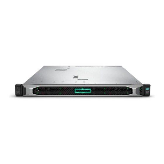
HPE ProLiant DL360 Gen10 Server User
Guide
Abstract
This document is for the person who installs, administers, and troubleshoots servers and storage
systems. Hewlett Packard Enterprise assumes you are qualified in the servicing of computer
equipment and trained in recognizing hazards in products with hazardous energy levels.
Part Number: 869840-002
Published: September 2017
Edition: 2
Advertisement
Table of Contents

Related Manuals for HP ProLiant DL360 Gen10


Summary of Contents for HP ProLiant DL360 Gen10
- Page 1 HPE ProLiant DL360 Gen10 Server User Guide Abstract This document is for the person who installs, administers, and troubleshoots servers and storage systems. Hewlett Packard Enterprise assumes you are qualified in the servicing of computer equipment and trained in recognizing hazards in products with hazardous energy levels.
- Page 2 © Copyright 2017 Hewlett Packard Enterprise Development LP Notices The information contained herein is subject to change without notice. The only warranties for Hewlett Packard Enterprise products and services are set forth in the express warranty statements accompanying such products and services. Nothing herein should be construed as constituting an additional warranty. Hewlett Packard Enterprise shall not be liable for technical or editorial errors or omissions contained herein.
-
Page 3: Table Of Contents
Contents Component identification................7 Front panel components........................7 Front panel LEDs and buttons......................8 UID button functionality......................11 Power fault LEDs........................11 Systems Insight Display LEDs......................11 Systems Insight Display combined LED descriptions................12 Rear panel components........................14 Rear panel LEDs..........................15 System board components........................16 System maintenance switch descriptions................ - Page 4 Selecting boot options in UEFI Boot Mode..................38 Selecting boot options........................38 Registering the server........................38 Hardware options installation..............39 Hewlett Packard Enterprise product QuickSpecs................39 Introduction............................39 Installing a redundant hot-plug power supply..................39 Memory options..........................40 DIMM population information....................40 HPE SmartMemory speed information................... 40 DIMM label identification......................41 Installing a DIMM........................
- Page 5 Installing a Smart Storage Battery in the 10 SFF SAS/SATA/NVMe Combo backplane configuration......................... 106 HPE Trusted Platform Module 2.0 Gen10 option................108 Overview..........................108 HPE Trusted Platform Module 2.0 Guidelines..............109 Installing and enabling the HPE TPM 2.0 Gen10 Kit............109 Cabling......................114 Cabling overview ..........................
- Page 6 Specifications..................132 Environmental specifications......................132 Server specifications........................132 Power supply specifications......................133 HPE 500W Flex Slot Platinum Hot Plug Low Halogen Power Supply........133 HPE 800W Flex Slot Platinum Hot Plug Low Halogen Power Supply........134 HPE 800W Flex Slot Titanium Hot Plug Low Halogen Power Supply........135 HPE 800W Flex Slot Universal Hot Plug Low Halogen Power Supply.........
-
Page 7: Component Identification
Component identification Front panel components 8 SFF Item Description Serial label pull tab Display port (optional) Optical drive (optional) USB 2.0 port (optional) USB 3.0 port iLO Service Port The operating system does not recognize this port as a USB port. SAS/SATA drive bays 4 LFF Item... -
Page 8: Front Panel Leds And Buttons
Item Description iLO Service Port The operating system does not recognize this port as a USB port. USB 3.0 port SAS/SATA drive bays 10 SFF NVMe/SAS Combo Item Description Serial label pull tab Systems Insight Display (optional) USB 3.0 port SAS/SATA/NVMe drive bays When the 10SFF NVMe/SAS backplane option is installed, NVMe drives must be installed in bays 9 and 10. - Page 9 Item Description Status UID button/LED* Solid blue = Activated Flashing blue: • 1 Hz = Remote management or firmware upgrade in progress • 4 Hz = iLO manual reboot sequence initiated • 8 Hz = iLO manual reboot sequence in progress Off = Deactivated Power On/Standby button and Solid green = System on...
- Page 10 4LFF Item Description Status UID button/LED* Solid blue = Activated Flashing blue: • 1 Hz = Remote management or firmware upgrade in progress • 4 Hz = iLO manual reboot sequence initiated • 8 Hz = iLO manual reboot sequence in progress Off = Deactivated NIC status LED* Solid green = Link to network...
-
Page 11: Uid Button Functionality
†Facility power is not present, power cord is not attached, no power supplies are installed, power supply failure has occurred, or the power button cable is disconnected. UID button functionality The UID button can be used to display the HPE ProLiant Pre-boot Health Summary when the server will not power on. -
Page 12: Systems Insight Display Combined Led Descriptions
Description Status Processor LEDs Off = Normal Amber = Failed processor DIMM LEDs Off = Normal Amber = Failed DIMM or configuration issue Fan LEDs Off = Normal Amber = Failed fan or missing fan NIC LEDs Off = No link to network Solid green = Network link Flashing green = Network link with activity If power is off, the front panel LED is not active. - Page 13 Systems Insight Display Health System Status LED and color power LED Processor (amber) Amber One or more of the following conditions may exist: • Processor in socket X has failed. • Processor X is not installed in the socket. • Processor X is unsupported.
-
Page 14: Rear Panel Components
Systems Insight Display Health System Status LED and color power LED Power cap (off) — Amber Standby Power cap (green) — Flashing Waiting for power green Power cap (green) — Green Power is available. Power cap (flashing amber) — Amber Power is not available. -
Page 15: Rear Panel Leds
Rear panel LEDs Item Description Status UID LED Solid blue = Identification is activated. Flashing blue = System is being managed remotely. Off = Identification is deactivated. iLO 5/standard Solid green = Activity exists. NIC activity LED Flashing green = Activity exists. Off = No activity exists. -
Page 16: System Board Components
System board components Item Description FlexibleLOM connector Primary (processor 1) PCIe riser connector System maintenance switch Front display port/USB 2.0 connector x4 SATA port 1 x4 SATA port 2 x2 SATA port 3 x1 SATA port 4 Front power/USB 3.0 connector Optical/SATA port 5 Smart Storage Battery connector Micro SD card slot... -
Page 17: System Maintenance Switch Descriptions
System maintenance switch descriptions Position Default Function Off = iLO security is enabled. On = iLO security is disabled. Off = System configuration can be changed. On = System configuration is locked. Reserved Reserved Off = Power-on password is enabled. On = Power-on password is disabled. -
Page 18: Device Numbers
Device numbers 8SFF device bay numbering 8SFF + 2 SFF device bay numbering Item Description Box 1, bays 1-8 Box 2, bays 1 and 2 4LFF device bay numbering Device numbers... -
Page 19: Hot-Plug Drive Led Definitions
10SFF NVMe/SAS backplane option device bay numbering When the 10SFF NVMe/SAS backplane option is installed, NVMe drives must be installed in bays 9 and 10.The other bays support a mix of NVMe and SAS drives. Optional rear device bay numbering The optional rear device bay supports either 1 SFF drive in a SmartDrive carrier, or 2 uFF M.2 drives in an HPE Smart Carrier M.2 (SCM). -
Page 20: Nvme Ssd Components
Item Status Definition Removing the drive does not cause a logical drive to fail. Drive status Solid green The drive is a member of one or more logical drives. Flashing green The drive is rebuilding or performing a RAID migration, strip size migration, capacity expansion, or logical drive extension, or is erasing. -
Page 21: Uff Drive Components And Leds
Drive status LED Solid green = The drive is a member of one or more logical drives. Flashing green = The drive is rebuilding or performing a RAID migration, stripe size migration, capacity expansion, or logical drive extension, or is erasing. Flashing amber/green = The drive is a member of one or more logical drives and predicts the drive will fail. -
Page 22: Hot-Plug Fans
Item Description Status Locate • Off—Normal • Solid blue—The drive is being identified by a host application • Flashing blue—The drive firmware is being updated or requires an update uFF drive ejection latch Removes the uFF drive when released Do not remove LED •... - Page 23 Two-processor configuration Fan bay 1 Fan bay 2 Fan bay 3 Fan bay 4 Fan bay 5 Fan bay 6 Fan bay 7 The loss of a single fan rotor (one standard fan) causes loss of redundancy. The loss of two fan rotors (2 standard fans or 1 high-performance fan) causes the server to initiate a shut down.
-
Page 24: Operations
Operations Powering up the server Procedure To power up the server, press the Power On/Standby button. Power down the server Before powering down the server for any upgrade or maintenance procedures, perform a backup of critical server data and programs. IMPORTANT: When the server is in standby mode, auxiliary power is still being provided to the system. -
Page 25: Remove The Server From The Rack
WARNING: To reduce the risk of personal injury, be careful when pressing the server rail-release latches and sliding the server into the rack. The sliding rails could pinch your fingers. 5. After performing the installation or maintenance procedure, slide the server into the rack: a. -
Page 26: Remove The Hot-Plug Fan
Remove the hot-plug fan Procedure 1. Observe the following alert: IMPORTANT: After removing a high-performance (dual-rotor) fan, install or replace the fan within 60 seconds. Otherwise, the server will shut down gracefully. 2. Do one of the following: a. Extend the server from the rack (Extend the server from the rack on page 24). b. -
Page 27: Removing The Primary Pci Riser Cage
CAUTION: Do not operate the server for long periods with the access panel open or removed. Operating the server in this manner results in improper airflow and improper cooling that can lead to thermal damage. IMPORTANT: For optimum cooling, install fans in all primary fan locations. To replace the component, reverse the removal procedure. -
Page 28: Install The Primary Pci Riser Cage
Install the primary PCI riser cage Procedure 1. Install the PCI riser cage. 2. Install the access panel (Installing the access panel on page 25). 3. Install the server into the rack (Installing the server into the rack on page 36). 4. -
Page 29: Install The Secondary Pci Riser Cage
10. Remove the PCI riser cage. Install the secondary PCI riser cage Procedure 1. Install the PCI riser cage. Install the secondary PCI riser cage... -
Page 30: Removing The 8 Sff Drive Backplane
2. If needed, install expansion boards (Installing an expansion board in the secondary riser cage on page 77). 3. Install the access panel (Installing the access panel on page 25). 4. Install the server into the rack (Installing the server into the rack on page 36). 5. -
Page 31: Releasing The Cable Management Arm
Releasing the cable management arm Release the cable management arm and then swing the arm away from the rack. Releasing the cable management arm... -
Page 32: Setup
Setup Optional service Delivered by experienced, certified engineers, Hewlett Packard Enterprise support services help you keep your servers up and running with support packages tailored specifically for HPE ProLiant systems. Hewlett Packard Enterprise support services let you integrate both hardware and software support into a single package. -
Page 33: Temperature Requirements
CAUTION: To prevent improper cooling and damage to the equipment, do not block the ventilation openings. When vertical space in the rack is not filled by a server or rack component, the gaps between the components cause changes in airflow through the rack and across the servers. Cover all gaps with blanking panels to maintain proper airflow. -
Page 34: Electrical Grounding Requirements
for Protection of Electronic Computer/Data Processing Equipment). For electrical power ratings on options, refer to the product rating label or the user documentation supplied with that option. WARNING: To reduce the risk of personal injury, fire, or damage to the equipment, do not overload the AC supply branch circuit that provides power to the rack. -
Page 35: Rack Warnings
CAUTION: If the DC connection exists between the earthed conductor of the DC supply circuit and the earthing conductor at the server equipment, the following conditions must be met: • This equipment must be connected directly to the DC supply system earthing electrode conductor or to a bonding jumper from an earthing terminal bar or bus to which the DC supply system earthing electrode conductor is connected. -
Page 36: Identifying The Contents Of The Server Shipping Carton
WARNING: To reduce the risk of personal injury or damage to the equipment, adequately stabilize the rack before extending a component outside the rack. Extend only one component at a time. A rack may become unstable if more than one component is extended. WARNING: When installing a server in a telco rack, be sure that the rack frame is adequately secured at the top and bottom to the building structure. -
Page 37: Operating System
CAUTION: Always plan the rack installation so that the heaviest item is on the bottom of the rack. Install the heaviest item first, and continue to populate the rack from the bottom to the top. Procedure 1. Install the server and cable management arm into the rack. For more information, see the installation instructions that ship with the selected rail system. -
Page 38: Selecting Boot Options In Uefi Boot Mode
Selecting boot options in UEFI Boot Mode On servers operating in UEFI Boot Mode, the boot controller and boot order are set automatically. Procedure 1. Press the Power On/Standby button. 2. During the initial boot: • To modify the server configuration ROM default settings, press the F9 key in the ProLiant POST screen to enter the UEFI System Utilities screen. -
Page 39: Hardware Options Installation
Hardware options installation Hewlett Packard Enterprise product QuickSpecs For more information about product features, specifications, options, configurations, and compatibility, see the product QuickSpecs on the Hewlett Packard Enterprise website (http://www.hpe.com/info/qs). Introduction If more than one option is being installed, read the installation instructions for all the hardware options and identify similar steps to streamline the installation process. -
Page 40: Memory Options
4. Insert the power supply into the power supply bay until it clicks into place. 5. Connect the power cord to the power supply. 6. Route the power cord. Use best practices when routing power cords and other cables. A cable management arm is available to help with routing. -
Page 41: Dimm Label Identification
DIMM label identification To determine DIMM characteristics, see the label attached to the DIMM. The information in this section helps you to use the label to locate specific information about the DIMM. Item Description Definition Capacity 8 GB 16 GB 32 GB 64 GB 128 GB... -
Page 42: Installing A Dimm
Item Description Definition CAS latency P = CAS 15-15-15 T = CAS 17-17-17 U = CAS 20-18-18 V = CAS 19-19-19 (for RDIMM, LRDIMM) V = CAS 22-19-19 (for 3DS TSV LRDIMM) DIMM type R = RDIMM (registered) L = LRDIMM (load reduced) E = Unbuffered ECC (UDIMM) For more information about product features, specifications, options, configurations, and compatibility, see the product QuickSpecs on the Hewlett Packard Enterprise website (http://www.hpe.com/info/qs). -
Page 43: Installing A High-Performance Fan
Install the access panel (Installing the access panel on page 25). Install the server in the rack. Connect each power cord to the server. 10. Connect each power cord to the power source. 11. Power up the server (Powering up the server on page 24). Use the BIOS/Platform Configuration (RBSU) in the UEFI System Utilities to configure the memory mode. - Page 44 Do one of the following: a. Extend the server from the rack (Extend the server from the rack on page 24). b. Remove the server from the rack (Remove the server from the rack on page 25). Remove the access panel (Remove the access panel on page 25). Remove all standard fans from the fan bays.
-
Page 45: Drive Options
Install the access panel (Installing the access panel on page 25). 10. Slide the server into the rack. 11. Connect each power cord to the server. 12. Connect each power cord to the power source. 13. Power up the server (Powering up the server on page 24). Drive options Depending on the configuration, this server supports SAS, SATA, and NVMe drives. -
Page 46: Installing A Hot-Plug Sas Or Sata Drive
Installing a hot-plug SAS or SATA drive Prerequisites Before installing this option, be sure that you have the following: The components included with the hardware option kit Procedure 1. Remove the drive blank. 2. Prepare the drive. 3. Install the drive. Installing a hot-plug SAS or SATA drive... -
Page 47: Removing A Hot-Plug Sas Or Sata Hard Drive
4. Determine the status of the drive from the drive LED definitions (Hot-plug drive LED definitions on page 19). Removing a hot-plug SAS or SATA hard drive CAUTION: For proper cooling, do not operate the server without the access panel, baffles, expansion slot covers, or blanks installed. -
Page 48: Removing And Replacing An Nvme Drive
CAUTION: To prevent improper cooling and thermal damage, do not operate the server unless all bays are populated with either a component or a blank. 2. Remove the drive blank, if installed. 3. Press the Do Not Remove button to open the release handle. 4. -
Page 49: Installing A Uff Drive And Scm Drive Carrier
Procedure 1. Back up all server data. 2. Observe the LED status of the drive and determine if it can be removed. 3. Remove the drive: a. Push the Power button. The Do Not Remove button illuminates and flashes. b. Wait until the flashing stops and the Do Not Remove button is no longer illuminated. c. -
Page 50: Removing And Replacing A Uff Drive
Push firmly near the ejection handle until the latching spring engages with the drive bay. 4. Power on the server. To configure the drive, use HPE Smart Storage Administrator. Removing and replacing a uFF drive Procedure 1. Back up all server data. 2. -
Page 51: Installing An 8 Sff Optical Drive
To replace the component, reverse the removal procedure. Installing an 8 SFF optical drive Prerequisites Before installing an optical drive, be sure the 8 SFF display port/USB/optical blank option is installed. For more information, see Installing an 8 SFF display port/USB/optical blank option on page 59. Procedure 1. -
Page 52: Universal Media Bay Options
Universal media bay options Installing a 2 SFF SAS/SATA drive cage Prerequisites Universal media bay options are compatible only with the 8 SFF chassis. Hewlett Packard Enterprise recommends installing the P816i-a controller to support 10 SAS/SATA drives. For more information, see Installing an HPE Smart Array P816i-a Controller option on page 87. Additional controller options are available. - Page 53 Install the 2 SFF SAS/SATA drive cage. Observe the following: NOTE: The following information describes the standard cable routing for this component. For more information on optional cable routing, see the Hewlett Packard Enterprise DL360 Gen10 Server cabling matrix on the Hewlett Packard Enterprise website (http://www.hpe.com/info/ CablingMatrixGen10).
-
Page 54: Installing A 2 Sff Nvme Drive Cage Option
10. Route and connect the power cable. 11. Install the access panel (Installing the access panel on page 25). 12. Install the server in the rack. 13. Connect each power cord to the server. 14. Connect each power cord to the power source. 15. - Page 55 For more information, contact a Hewlett Packard Enterprise authorized reseller. Procedure Back up all server data. Power down the server (Power down the server on page 24). Remove all power: a. Disconnect each power cord from the power source. b. Disconnect each power cord from the server. Do one of the following: a.
- Page 56 10. Install the riser provided in the kit in the primary PCI riser cage. 11. Observe the following: NOTE: The following information describes the standard cable routing for this component. For more information on optional cable routing, see the Hewlett Packard Enterprise DL360 Gen10 Server cabling matrix on the Hewlett Packard Enterprise website (http://www.hpe.com/info/ CablingMatrixGen10).
-
Page 57: Installing A 2 Sff Hpe Smart Carrier M.2 (Scm) Drive Cage
17. Connect each power cord to the power source. 18. Power up the server (Powering up the server on page 24). 19. Install drives. Installing a 2 SFF HPE Smart Carrier M.2 (SCM) drive cage Prerequisites Hewlett Packard Enterprise recommends installing the P816i-a controller to support more than eight SAS/ SATA drives. - Page 58 Observe the following: NOTE: The following information describes the standard cable routing for this component. For more information on optional cable routing, see the Hewlett Packard Enterprise DL360 Gen10 Server cabling matrix on the Hewlett Packard Enterprise website (http://www.hpe.com/info/ CablingMatrixGen10). Route and connect the data cable.
-
Page 59: Installing An 8 Sff Display Port/Usb/Optical Blank Option
11. Install the access panel (Installing the access panel on page 25). 12. Install the server in the rack. 13. Connect each power cord to the server. 14. Connect each power cord to the power source. 15. Power up the server (Powering up the server on page 24). 16. - Page 60 Install the 8 SFF display port/USB/optical blank option. Route and connect the data cable. Hardware options installation...
-
Page 61: Installing The 4 Lff Optical Drive Option
If needed, install an optical drive (Installing an 8 SFF optical drive on page 51). 10. Install the access panel (Installing the access panel on page 25). 11. Install the server in the rack. 12. Connect each power cord to the server. 13. - Page 62 Install the optical drive. Observe the following: NOTE: The following information describes the standard cable routing for this component. For more information on optional cable routing, see the Hewlett Packard Enterprise DL360 Gen10 Server cabling matrix on the Hewlett Packard Enterprise website (http://www.hpe.com/info/ CablingMatrixGen10).
-
Page 63: Installing The Rear Drive Riser Cage Option
10. Install the access panel (Installing the access panel on page 25). 11. Install the server in the rack. 12. Connect each power cord to the server. 13. Connect each power cord to the power source. 14. Power up the server (Powering up the server on page 24). Installing the rear drive riser cage option The rear drive riser cage option supports low-profile PCI riser options in slot 2. - Page 64 Remove the riser board. Set aside for later use. If installed, remove the slot 2 bracket from the primary riser cage. If needed, install the riser board removed in step 7 on the rear drive riser cage bracket. Hardware options installation...
- Page 65 10. Install the drive cage on the riser cage. 11. If needed, install the riser cage bracket on the rear drive riser cage. 12. If needed, install an expansion board (Installing an expansion board in the primary riser cage on page 70).
-
Page 66: Primary Pci Riser Cage Options
14. Route and connect the data and power cables. Hewlett Packard Enterprise recommends using embedded SATA solutions when connecting the cable. Other options exist. For more information, see the HPE DL360 Gen10 Server cabling matrix on the Hewlett Packard Enterprise website (http://www.hpe.com/info/CablingMatrixGen10). 15. -
Page 67: Installing An Optional Primary Pci Riser Board
◦ Half-length, half-height expansion boards ◦ 3/4-length expansion boards when either a low-profile type -a controller or no controller is installed. Installing an optional primary PCI riser board Prerequisites Before installing this option, be sure you have the following: • The components included with the hardware option kit •... -
Page 68: Installing The Sata M.2 2280 Riser Option
10. Install the following, as needed: • Expansion boards (Installing an expansion board in the primary riser cage on page 70) • GPU (Installing the primary GPU riser and cable option on page 71) • Controllers (Controller options on page 82) 11. - Page 69 Remove the existing riser board from the riser cage. Install the M.2 riser board. Remove the screw securing the standoff on the riser. 10. Install the M.2 drives. 11. Install the following, as needed: Hardware options installation...
-
Page 70: Installing An Expansion Board In The Primary Riser Cage
• Expansion boards (Installing an expansion board in the primary riser cage on page 70) • Controllers (Controller options on page 82) 12. Install the primary PCI riser cage (Install the primary PCI riser cage on page 28). 13. Install the access panel (Installing the access panel on page 25). 14. -
Page 71: Installing The Primary Gpu Riser And Cable Option
Install the expansion board. 10. Connect any required internal or external cables to the expansion board. 11. Install the primary PCI riser cage (Install the primary PCI riser cage on page 28). 12. Install the access panel (Installing the access panel on page 25). 13. - Page 72 • The components included with the hardware option kit • HPE DL360 Gen10 CPU1 Cable Kit (If installing a high-powered GPU kit) Procedure Observe the following alerts: WARNING: To reduce the risk of personal injury from hot surfaces, allow the drives and the internal system components to cool before touching them.
-
Page 73: Secondary Pci Riser Options
11. Install the riser cage (Install the primary PCI riser cage on page 28). 12. Install the access panel (Installing the access panel on page 25). 13. Install the server in the rack. 14. Connect each power cord to the server. 15. - Page 74 If installed, remove the low-profile riser cage. Lift and remove the secondary riser cage latch. Hardware options installation...
- Page 75 Install the full height PCIe x16 riser cage latch. 10. Install the riser cage. Hardware options installation...
-
Page 76: Installing A Secondary Low-Profile Pcie Slot Riser Cage Option
11. Install one of the following, as needed: • Expansion boards (Installing an expansion board in the secondary riser cage on page 77) • GPU (Installing a secondary GPU riser and cable option on page 80) • Controllers (Controller options on page 82) 12. -
Page 77: Installing An Expansion Board In The Secondary Riser Cage
Remove all power: a. Disconnect each power cord from the power source. b. Disconnect each power cord from the server. Do one of the following: a. Extend the server from the rack (Extend the server from the rack on page 24). b. - Page 78 CAUTION: To prevent damage to electrical components, properly ground the server before beginning any installation procedure. Improper grounding can cause electrostatic discharge. Back up all server data. Power down the server (Power down the server on page 24). Remove all power: a.
- Page 79 • Full-length Install the expansion board. Hardware options installation...
-
Page 80: Installing A Secondary Gpu Riser And Cable Option
10. Connect any required internal or external cables to the expansion board. 11. Install the access panel (Installing the access panel on page 25). 12. Install the server in the rack. 13. Connect each power cord to the server. 14. Connect each power cord to the power source. 15. - Page 81 a. Disconnect each power cord from the power source. b. Disconnect each power cord from the server. Do one of the following: a. Extend the server from the rack (Extend the server from the rack on page 24). b. Remove the server from the rack (Remove the server from the rack on page 25). Remove the access panel (Remove the access panel on page 25).
-
Page 82: Controller Options
13. Install the access panel (Installing the access panel on page 25). 14. Install the server in the rack. 15. Connect each power cord to the server. 16. Connect each power cord to the power source. 17. Power up the server (Powering up the server on page 24). Controller options Installing an HPE Smart Array P408i-a Controller option Prerequisites... - Page 83 a. Extend the server from the rack (Extend the server from the rack on page 24). b. Remove the server from the rack (Remove the server from the rack on page 25). Remove the access panel (Remove the access panel on page 25). Install the controller.
-
Page 84: Installing An Hpe Smart Array P408I-P Controller Option
• 4 LFF Install the access panel (Installing the access panel on page 25). 10. Install the server in the rack. 11. Connect each power cord to the server. 12. Connect each power cord to the power source. 13. Power up the server (Powering up the server on page 24). Installing an HPE Smart Array P408i-p Controller option Prerequisites Before installing this option, be sure you have the following:... - Page 85 WARNING: To reduce the risk of personal injury from hot surfaces, allow the drives and the internal system components to cool before touching them. CAUTION: To prevent damage to electrical components, properly ground the server before beginning any installation procedure. Improper grounding can cause electrostatic discharge. Back up all server data.
- Page 86 10. Install the primary PCI riser cage (Install the primary PCI riser cage on page 28). 11. Connect the cables. Additional cabling options are available. For more information, see the HPE DL360 Gen10 Server cabling matrix on the Hewlett Packard Enterprise website (http://www.hpe.com/info/CablingMatrixGen10). •...
-
Page 87: Installing An Hpe Smart Array P816I-A Controller Option
12. Install the access panel (Installing the access panel on page 25). 13. Install the server in the rack. 14. Connect each power cord to the server. 15. Connect each power cord to the power source. 16. Power up the server (Powering up the server on page 24). Installing an HPE Smart Array P816i-a Controller option Prerequisites Before installing this option, be sure that you have the following:... - Page 88 a. Extend the server from the rack (Extend the server from the rack on page 24). b. Remove the server from the rack (Remove the server from the rack on page 25). Remove the access panel (Remove the access panel on page 25). Install the HPE Smart Array P816i-a controller.
-
Page 89: Processor And Heatsink Options
Processor and heatsink options Installing a processor heatsink assembly The server supports single-processor and dual processor operations. Prerequisites Before installing this option, be sure that you have the following items: • Processor or heatsink kit contents • T-30 Torx screwdriver Procedure Observe the following alerts. - Page 90 CAUTION: Be sure to tighten each heatsink nut fully in the order indicated. Otherwise, boot failure or intermittent shutdowns might occur. c. Using a T-30 Torx screwdriver, fully tighten each heatsink nut in the order indicated on the heatsink label (1 -2 -3 -4) until it no longer turns. If installing a second processor, install high-performance fans in bays 7 and 8.
-
Page 91: Installing A High-Performance Heatsink
12. Connect each power cord to the power source. 13. Power up the server (Powering up the server on page 24). Installing a high-performance heatsink Prerequisites CAUTION: Installing a high-performance heatsink requires the installation of a processor assembly onto the heatsink. - Page 92 Remove the existing processor heatsink assembly: a. Allow the heatsink to cool. b. Using a T-30 Torx screwdriver, loosen the heatsink nuts. c. Lift the processor heatsink assembly up and away from the system board. d. Turn the processor heatsink assembly over and place it on a work surface with the processor assembly facing up.
- Page 93 d. Unlatch the remaining corners of the processor assembly. e. Separate the processor assembly from the heatsink. The processor remains attached to the carrier. Using an alcohol wipe, remove the existing thermal grease from the processor and heatsink. Allow the alcohol to evaporate before continuing.
-
Page 94: Installing The Systems Insight Display Power Module
CAUTION: Be sure to tighten each heatsink nut fully in the order indicated. Otherwise, boot failure or intermittent shutdowns might occur. Using a T-30 Torx screwdriver, fully tighten each heatsink nut until it no longer turns. Installing the Systems Insight Display power module Prerequisites Before installing this option, be sure you have the following: •... - Page 95 Procedure Observe the following alerts: WARNING: To reduce the risk of personal injury from hot surfaces, allow the drives and the internal system components to cool before touching them. CAUTION: To prevent damage to electrical components, properly ground the server before beginning any installation procedure.
- Page 96 • 4 LFF Guide the SID cable through the front of the server. Hardware options installation...
- Page 97 10. Install the SID module into the front panel. Using a T-10 Torx screwdriver, secure the module to the chassis with the screws from the kit. • 8 SFF • 4 LFF Hardware options installation...
-
Page 98: Installing The 4 Lff Display Port/Usb Module
11. Connect the SID cables to the front power button/USB 3.0 connector on the system board. Installing the 4 LFF display port/USB module Prerequisites Before installing this option, be sure you have the following: • The components included with the hardware option kit •... - Page 99 a. Extend the server from the rack (Extend the server from the rack on page 24). b. Remove the server from the rack (Remove the server from the rack on page 25). Remove the access panel (Remove the access panel on page 25). Using a Torx T-10 screwdriver, remove the 4 LFF display port/USB blank.
-
Page 100: Installing The Serial Cable Option
Install the access panel (Installing the access panel on page 25). Install the server in the rack. 10. Connect each power cord to the server. 11. Connect each power cord to the power source. 12. Power up the server (Powering up the server on page 24). Installing the serial cable option Prerequisites Before installing this option, be sure you have the following:... -
Page 101: Installing The Chassis Intrusion Detection Switch Option
Remove the access panel (Remove the access panel on page 25). Remove the serial cable blank. Connect the serial cable option, and then secure the cable with two T-10 screws. Then, remove the backing from the double-sided tape and press down where indicated. Install the access panel (Installing the access panel on page 25). - Page 102 Procedure Power down the server (Power down the server on page 24). Remove all power: a. Disconnect each power cord from the power source. b. Disconnect each power cord from the server. Do one of the following: a. Extend the server from the rack (Extend the server from the rack on page 24). b.
-
Page 103: Installing A Flexiblelom Option
Install the access panel (Installing the access panel on page 25). 10. Install the server in the rack. 11. Connect each power cord to the server. 12. Connect each power cord to the power source. 13. Power up the server (Powering up the server on page 24). Installing a FlexibleLOM option Prerequisites Before installing this option, be sure that you have the following:... - Page 104 Install the component: a. Firmly seat the FlexibleLOM in the slot. b. Tighten the thumbscrew. Install the access panel (Installing the access panel on page 25). Slide the server into the rack. Connect the LAN segment cables. 10. Connect each power cord to the server. 11.
-
Page 105: Hpe Smart Storage Battery Option
HPE Smart Storage Battery option In the Hewlett Packard Enterprise DL360 Gen10 Server , the Smart Storage Battery can be installed in two different orientations, depending on configuration: • Installing a Smart Storage Battery in 8 SFF and 4 LFF configurations on page 105 •... -
Page 106: Installing A Smart Storage Battery In The 10 Sff Sas/Sata/Nvme Combo Backplane Configuration
Installing a Smart Storage Battery in the 10 SFF SAS/SATA/NVMe Combo backplane configuration Prerequisites The Smart Storage Battery must be installed in this orientation when the 10 SFF SAS/SATA/NVMe Combo backplane is installed. Procedure Power down the server (Power down the server on page 24). Remove all power: a. - Page 107 Connect the cable: a. Remove the center fan baffle. b. Connect the Smart Storage battery cable to the extender cable. Hardware options installation...
-
Page 108: Hpe Trusted Platform Module 2.0 Gen10 Option
c. Install the center fan baffle. Install the access panel (Installing the access panel on page 25). Install the server in the rack. 10. Connect each power cord to the server. 11. Connect each power cord to the power source. 12. -
Page 109: Hpe Trusted Platform Module 2.0 Guidelines
HPE Trusted Platform Module 2.0 Guidelines CAUTION: Always observe the guidelines in this document. Failure to follow these guidelines can cause hardware damage or halt data access. When installing or replacing a TPM, observe the following guidelines: • Do not remove an installed TPM. Once installed, the TPM is bound to the system board. If an OS is configured to use the TPM and it is removed, the OS may go into recovery mode, data loss can occur, or both. - Page 110 a. Disconnect each power cord from the power source. b. Disconnect each power cord from the server. Do one of the following: • Extend the server from the rack (Extend the server from the rack on page 24). • Remove the server from the rack (Remove the server from the rack on page 25). Place the server on a flat, level work surface.
- Page 111 3. Install the TPM cover: a. Line up the tabs on the cover with the openings on either side of the TPM connector. b. To snap the cover into place, firmly press straight down on the middle of the cover. 4.
-
Page 112: Enabling The Trusted Platform Module
Enabling the Trusted Platform Module When enabling the Trusted Platform module, observe the following guidelines: • By default, the Trusted Platform Module is enabled as TPM 2.0 when the server is powered on after installing it. • In UEFI Boot Mode, the Trusted Platform Module can be configured to operate as TPM 2.0 or TPM 1.2. •... - Page 113 • If in graphical mode, click Yes. • If in text mode, press the Y key. 7. Press the ESC key to exit System Utilities. The server reboots a second time without user input. During this reboot, the TPM setting becomes effective.
-
Page 114: Cabling
Cabling Cabling overview This section provides guidelines that help you make informed decisions about cabling the server and hardware options to optimize performance. CAUTION: When routing cables, always be sure that the cables are not in a position where they can be pinched or crimped. -
Page 115: Sff Configuration Cable Routing
Option kit Cable part number Connects from Connects to 869681-001 10 SFF backplane, port 5 NVMe riser, port 5 869680-001 10 SFF backplane, port 4 NVMe riser, port 4 SFF configuration cable routing NOTE: The following information describes the standard cable routing for this component. For more information on optional cable routing, see the Hewlett Packard Enterprise DL360 Gen10 Server cabling matrix on the Hewlett Packard Enterprise website (http://www.hpe.com/info/CablingMatrixGen10). -
Page 116: Additional Sff Cabling
2 SFF NVMe backplane to primary riser 1 SFF rear backplane to system board SATA Additional SFF cabling For more information on the following cables and cabling configurations, see the HPE DL360 Gen10 Server cabling matrix on the Hewlett Packard Enterprise website (http://www.hpe.com/info/CablingMatrixGen10): •... -
Page 117: Lff Cables
LFF cables Option kit Cable part number Connects from Connects to HPE DL360 Gen10 LFF 869673-001 4 LFF backplane Type -p Smart Array Internal Cable Kit controller, slot 1 Type -a Smart Array controller Embedded SATA 874616-001 4 LFF backplane PCI controller, slot 2 HPE DL360 Gen9 LFF 756914-001... -
Page 118: Software And Configuration Utilities
Software and configuration utilities Server mode The software and configuration utilities presented in this section operate in online mode, offline mode, or in both modes. Software or configuration utility Server mode Active Health System on page 118 Online and Offline HPE iLO 5 on page 119 Online and Offline HPE Smart Storage Administrator on page 124... -
Page 119: Hpe Ilo 5
• Consolidated health and service alerts with precise time stamps • Agentless monitoring that does not affect application performance For more information about the Active Health System, see the iLO user guide on the Hewlett Packard Enterprise website. Active Health System data collection The Active Health System does not collect information about your operations, finances, customers, employees, or partners. -
Page 120: Ilo Service Port
iLO supports the following features: • Group health status—View server health and model information. • Group Virtual Media—Connect scripted media for access by the servers in an iLO Federation group. • Group power control—Manage the power status of the servers in an iLO Federation group. •... -
Page 121: Restful Interface Tool
RESTful Interface Tool The RESTful Interface Tool (iLOrest) is a scripting tool that allows you to automate HPE server management tasks. It provides a set of simplified commands that take advantage of the iLO RESTful API. You can install the tool on your computer for remote use or install it locally on a server with a Windows or Linux Operating System. -
Page 122: Management Security
IMPORTANT: • Although your server is pre-loaded with firmware and drivers, you should update the firmware upon initial setup to ensure you have the latest versions. Also, downloading and updating the latest version of Intelligent Provisioning ensures the latest supported features are available. •... -
Page 123: Selecting The Boot Mode
• Configuring system devices and installed options. • Enabling and disabling system features. • Displaying system information. • Selecting the primary boot controller or partition. • Configuring memory options. • Launching other preboot environments. HPE servers with UEFI can provide: •... -
Page 124: Launching The Embedded Uefi Shell
• Preboot UEFI Shell applications • OS UEFI boot loaders When Secure Boot is enabled: • Firmware components and operating systems with boot loaders must have an appropriate digital signature to execute during the boot process. • Operating systems must support Secure Boot and have an EFI boot loader signed with one of the authorized keys to boot. -
Page 125: Usb Support
HPE SSA is accessible both offline (either through HPE Intelligent Provisioning or as a standalone bootable ISO image) and online: • Accessing HPE SSA in the offline environment IMPORTANT: If you are updating an existing server in an offline environment, obtain the latest version of HPE SSA through Service Pack for ProLiant before performing configuration procedures. - Page 126 • Service Pack for ProLiant (SPP) • HPE online flash components Service Pack for ProLiant SPP is a systems software and firmware solution delivered as a single ISO file download. This solution uses SUM as the deployment tool and is tested on supported ProLiant servers. SPP, along with SUM and SUT, provides Smart Update system maintenance tools that systematically update ProLiant servers and BladeSystem infrastructure.
- Page 127 polling interval by issuing the appropriate command-line option provided by SUT. Performs inventory on target servers, stages deployment, deploys updates, and then reboots the servers. • iLO 5 with integrated Smart Update (Gen10 servers only): Loads Install Sets to the iLO Repository on iLO 5 nodes.
-
Page 128: Drivers
6. Change to the file system that contains the System ROM Flash Binary component for your server. Enter one of the fsx file systems available, such as fs0: or fs1:, and press Enter. 7. Use the cd command to change from the current directory to the directory that contains the binary file. 8. -
Page 129: Proactive Notifications
• Private or hybrid cloud computing • Big data and mobility requirements • Improving data center infrastructure • Better use of server, storage, and networking technology For more information, see the Hewlett Packard Enterprise website: http://www.hpe.com/services/consulting Proactive notifications 30 to 60 days in advance, Hewlett Packard Enterprise sends notifications to subscribed customers on upcoming: •... -
Page 130: Troubleshooting
Troubleshooting Troubleshooting resources Troubleshooting resources are available for HPE Gen10 server products in the following documents: • Troubleshooting Guide for HPE ProLiant Gen10 servers provides procedures for resolving common problems and comprehensive courses of action for fault isolation and identification, issue resolution, and software maintenance. -
Page 131: Removing And Replacing The System Battery
Removing and replacing the system battery The system battery provides power to the real-time clock. If the server no longer automatically displays the correct date and time, you might need to replace the system battery. WARNING: The computer contains an internal lithium manganese dioxide, a vanadium pentoxide, or an alkaline battery pack. -
Page 132: Specifications
Specifications Environmental specifications Specification Value Temperature range — Operating 10°C to 35°C (50°F to 95°F) Nonoperating -30°C to 60°C (-22°F to 140°F) Relative humidity (noncondensing) — Operating Minimum to be the higher (more moisture) of -12°C (10.4°F) dew point or 8% relative humidity Maximum to be 24°C (75.2°F) dew point or 90% relative humidity Nonoperating... -
Page 133: Power Supply Specifications
Specification Value 13.04 kg (28.74 lb) SFF minimum (one drive, one processor, one power supply, two heatsinks, one Smart Array controller, five fans) 16.27 kg (35.86 lb) SFF maximum (10 drives, two processors, two power supplies, two heatsinks, one Smart Array controller, seven fans) 13.77 kg (30.36 lb) LFF minimum (one drive, one... -
Page 134: Hpe 800W Flex Slot Platinum Hot Plug Low Halogen Power Supply
Specification Value Rated input current 5.8 A at 100 VAC 2.8 A at 200 VAC 2.4 A at 240 VDC for China only Maximum rated input power 557 W at 100 VAC 539 W at 200 VAC 537 W at 240 VDC for China only BTUs per hour 1,902 at 100 VAC 1,840 at 200 VAC... -
Page 135: Hpe 800W Flex Slot Titanium Hot Plug Low Halogen Power Supply
Specification Value BTUs per hour 3,067 at 100 VAC 2,958 at 200 VAC 2,949 at 240 VAC for China only Power supply output Rated steady-state power 800 W at 100 VAC to 127 VAC input 800 W at 100 VAC to 240 VAC input 800 W at 240 VDC input for China only Maximum peak power 800 W at 100 VAC to 127 VAC input... -
Page 136: Hpe 800W Flex Slot Universal Hot Plug Low Halogen Power Supply
HPE 800W Flex Slot Universal Hot Plug Low Halogen Power Supply Specification Value Input requirements Rated input voltage 200 VAC to 277 VAC Rated input frequency 50 Hz to 60 Hz Rated input current 4.4 A at 200 VAC 3.8 A at 230 VAC 3.1 A at 277 VAC Maximum rated input power 869 W at 200 VAC... -
Page 137: Hpe 1600W Flex Slot Platinum Hot Plug Low Halogen Power Supply
Specification Value Power supply output Rated steady-state power (W) 800 W at -40 VDC to -72 VDC Maximum peak power (W) 800 W at -40 VDC to -72 VDC Maximum peak power 800 W at 200 VAC to 277 VAC input 800 W at 380 VDC input WARNING: To reduce the risk of electric shock or energy hazards:... -
Page 138: Hot-Plug Power Supply Calculations
Specification Value Maximum rated input power 1,734 W at 200 VAC 1,725 W at 240 VAC BTUs per hour 5,918 at 200 VAC 5,884 at 240 VAC Power supply output Rated steady-state power 1,600 W at 200 VAC to 240 VAC input 1,600 W at 240 VDC input Maximum peak power 2,200 W for 1 ms (turbo mode) at 200 VAC to 240... -
Page 139: Websites
Websites General websites Hewlett Packard Enterprise Information Library www.hpe.com/info/EIL Single Point of Connectivity Knowledge (SPOCK) Storage compatibility matrix www.hpe.com/storage/spock Storage white papers and analyst reports www.hpe.com/storage/whitepapers For additional websites, see Support and other resources. Websites... -
Page 140: Support And Other Resources
Support and other resources Accessing Hewlett Packard Enterprise Support • For live assistance, go to the Contact Hewlett Packard Enterprise Worldwide website: http://www.hpe.com/assistance • To access documentation and support services, go to the Hewlett Packard Enterprise Support Center website: http://www.hpe.com/support/hpesc Information to collect •... -
Page 141: Remote Support
Some parts do not qualify for CSR. Your Hewlett Packard Enterprise authorized service provider will determine whether a repair can be accomplished by CSR. For more information about CSR, contact your local service provider or go to the CSR website: http://www.hpe.com/support/selfrepair Remote support Remote support is available with supported devices as part of your warranty or contractual support... -
Page 142: Regulatory Information
Regulatory information To view the regulatory information for your product, view the Safety and Compliance Information for Server, Storage, Power, Networking, and Rack Products, available at the Hewlett Packard Enterprise Support Center: www.hpe.com/support/Safety-Compliance-EnterpriseProducts Additional regulatory information Hewlett Packard Enterprise is committed to providing our customers with information about the chemical substances in our products as needed to comply with legal requirements such as REACH (Regulation EC No 1907/2006 of the European Parliament and the Council). -
Page 143: Acronyms And Abbreviations
Canadian Standards Association Customer Self Repair FSBBU Flex slot battery backup graphics processing unit host bus adapter HP SUM HP Software Update Manager HPE SSA HPE Smart Storage Administrator International Electrotechnical Commission Integrated Lights-Out Integrated Management Log Acronyms and abbreviations... - Page 144 International Organization for Standardization JSON JavaScript Object Notation large form factor LRDIMM load reduced dual in-line memory module NAND Not AND nonmaskable interrupt NVRAM nonvolatile memory PCIe Peripheral Component Interconnect Express power distribution unit POST Power-On Self-Test RBSU ROM-Based Setup Utility RDIMM registered dual in-line memory module REST...
- Page 145 Systems Insight Display Systems Insight Manager Service Pack for ProLiant TMRA recommended ambient operating temperature Trusted Platform Module UDIMM unregistered dual in-line memory module UEFI Unified Extensible Firmware Interface unit identification universal serial bus Virtual Connect Version Control Agent VCRM Version Control Repository Manager voltage direct-current Acronyms and abbreviations...