
Related Manuals for Honeywell Satellite XT


Summary of Contents for Honeywell Satellite XT
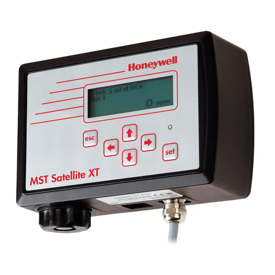
- Page 1 Guide to Operation Satellite XT R Version Including Options: Extractive Module XT Pyrolyzer Module XT...
-
Page 2: Table Of Contents
Sensor Infos....................4-6 4.6....Reset Device ....................4-8 4.7....Service......................4-8 Section 5 Calibration 5.1....Gas Calibration ................... 5-2 5.1.1 .... Zero Adjust ....................5-2 5.1.2 .... Span Adjust ....................5-3 5.2....Manual K-Factor ..................5-4 Satellite XT R Version toc-1... - Page 3 Principle of Operation ................10-1 10.2..... General Instructions................... 10-1 10.3..... Safety Instructions ..................10-1 10.4..... Instrument Design..................10-2 10.5..... Mounting....................10-3 10.6..... Tubing Connections................... 10-4 10.7..... Data Link....................10-4 10.8..... Power Connection ..................10-4 10.9..... Technical specifications................10-5 Satellite XT R Version toc-2...
-
Page 4: Principle Of Operation
This section provides a basic understanding of the instrument and its operation. Principle of Operation The Satellite XT R Version is a generic gas monitoring instrument for the detection of a wide range of hazardous gases. Power is supplied by a local 12 to 24 VDC power supply. -
Page 5: Maintenance Mode
Section 7, Troubleshooting. Menu structure Besides the Monitoring Mode, there is also menu operation for the Satellite XT. Menu operation comprises three groups of functions, maintenance, calibration, and configuration. A password (if enabled) must be entered to exit the Monitoring Mode and to obtain access to the Main Menu. -
Page 6: Operational Elements
Main Menu, in the right example it is the Sub-Menu Maintenance. Line 2 shows one of the selection possibilities. Line 3 shows the number of the selection possibility presently displayed and indicates also the total of selection possibilities available in this menu. Satellite XT R Version... -
Page 7: Technical Specifications
Operating Conditions -20 °C ... +40 °C temperature -4 °F ... +104 °F pressure 700 ... 1300 hPa humidity 20 ... 90 % r.h. Part Number Satellite XT R 9602-0505 Satellite XT R, IP 65 9612-0505 Satellite XT R Version... -
Page 8: Installation And Start-Up
Attach the wires to the junction box according to the wiring diagram provided in the course section. of this section. 90,0 Mounting rail standard (P/N 9602.0050.10.03) Mounting rail standard (P/N 9602.0050.10.03) 2 - 1 Satellite XT R Version Satellite XT R Version... - Page 9 For applications where wall mounting is not possible, an L-shaped mounting plate with DIN–rail is available as an option. Optional L-shaped mounting plate with DIN–rail (P/N 9602.0051.10.02) ! Note: Do not apply power until system is ready for start-up! Satellite XT R Version...
-
Page 10: Duct Mounting
Connecting the Sensor Extension to the Instrument Connect the Socket (A) to the plug in the sensor compartment located at the bottom of the Satellite XT. The groove of the Socket must face to the front. Screw in the Internal Cap (B) and fasten it hand-tight. -
Page 11: Mounting The Sensor Extension To The Duct
Mounting the Sensor Extension to the Duct Duct Duct 5,2cm *) Duct Mounting Saddle Assembly various types available, see spare parts list, Section 8, 3,3cm Reference Information 2,6cm 2,6cm Satellite XT Sensor Sensor Extension Duct Satellite XT Satellite XT R Version... -
Page 12: Wiring
Cable shield Note: All wiring for the Satellite XT and its related equipment must be in compliance with any local electrical and fire codes. The Satellite XT wiring must be kept away from any high power lines. All shielding for the wiring must be connected together and grounded at only one point in the system. - Page 13 3 m provided with instrument 2 m provided with instrument Junction Box 230 / 115 VAC Power Supply 24 VDC 2-wire shielded cable 2-wire shielded cable to additional control devices Wiring Diagram Satellite XT R - Basic Configuration Satellite XT R Version...
-
Page 14: Initial Start-Up
When wiring is completed, a sensor must be assigned to each instrument. Every sensor is gas calibrated and these sensor specific calibration parameters are stored in its integrated data memory. Make sure to use only sensors designed for use with the Satellite XT. Ex factory the instruments are shipped either unconfigured or already preconfigured according to the customer’s specifications. - Page 15 Installation and Start-Up - Section 2 Satellite XT R Version...
-
Page 16: The Main Menu Screens
C A L I B R A T I ON Sub-Menus s e l e c t : M E N U CON F I GU R A T I ON Sub-Menus s e l e c t : Satellite XT R Version... -
Page 17: Main Menu - Monitoring
(f.i. Alarm 1 set at 0.05 ppm AsH3) <Alarm 2 Condition> This screen shows that Alarm Level 2 has been exceeded and that there is an actual gas concentration of 0.12 ppm AsH3. (f.i. Alarm 2 set at 0.10 ppm AsH3) Satellite XT R Version... -
Page 18: Main Menu - Maintenance
: Service M A I N T E N A N C E screen 7 of 7 S E R V I C E s e l e c t : Satellite XT R Version... -
Page 19: Main Menu - Calibration
MA N U A L K - F A C T OR MA N U A L K - F A C T OR s e l e c t : s e l e c t : Satellite XT R Version... -
Page 20: Main Menu - Configuration
: Password C O N F I G U R A T I O N screen 6 of 10 P A S SWOR D s e l e c t : continued Continued Satellite XT R Version... - Page 21 : Relays C O N F I G U R A T I O N screen 10 of 10 R E L A Y S s e l e c t : Satellite XT R Version...
- Page 22 Sensor Infos M A I N T E N A N C E S E N S OR I N F O S screen 5 of 7 s e l e c t : Continued continued Satellite XT R Version...
- Page 23 : Service M A I N T E N A N C E screen 7 of 7 S E R V I C E s e l e c t : Satellite XT R Version...
- Page 24 This does not apply for oxygen sensors. The warm-up time required depends on the type of sensor. <Normal Monitoring Condition> The instrument will automatically switch to the Monitoring Mode when the sensor service procedure is finished. Satellite XT R Version...
- Page 25 S E T A L A R M 2 The Alam 2 Relay is activated. A l a r m 2 s e t ! Use the <esc> key to exit. < e s c > t o e x i t continued Continuación Satellite XT R Version...
- Page 26 : ! Note: Whenever a new sensor is installed, the K-factor will automatically revert to the default value 1.00. Any individual settings must be entered again; refer to section 5, Calibration. Satellite XT R Version...
- Page 27 This information may be required for service purposes 2 7 . 0 9 . 2 0 0 6 and to check the age of the sensor. Actuate <esc> to leave. < e s c > t o e x i t continued Continued Satellite XT R Version...
- Page 28 R E V I S I O N N U M B E R This information may be required for service purposes. Actuate the <esc> key to leave. < e s c > t o e x i t Satellite XT R Version...
- Page 29 The warm-up time depends on the type of sensor. <Normal Monitoring Condition> The instrument will automatically switch to the Monitoring Mode when the sensor service procedure is finished. Service This submenu is used exclusively by trained Service Personnel. The functions are password protected. Satellite XT R Version...
- Page 30 Calibration - Section 5 This section describes calibration procedures for the Satellite XT. Calibration can be performed either automatically using a dynamic gas calibration or manually by entering a calculated correction factor called K-factor. Main Menu - Calibration The instrument is in the Maintenance Mode and the M E N U green LED is off.
- Page 31 Actuate the <set> key to save the new zero point and S A V E ? store it in the unit’s internal memory. < s e t > t o c o n f i r m Continued continued Satellite XT R Version...
- Page 32 Stop the calibration gas flow. Remove gas and calibration R EMO V E G A S ! cap. Allow several minutes for the sensor to clear. V a l u e s a v e d Satellite XT R Version...
- Page 33 After a new value has been entered, actuate the <set> key to confirm or <esc> to exit. ! Note: Individual settings for the manual K-factor will automatically revert to the default value 1.00, whenever the sensor is replaced by a new sensor. Satellite XT R Version...
-
Page 34: Date Format
S E C U R I T Y s e l e c t : C O N F I G U R A T I O N P A S SWOR D s e l e c t : Continued continued Satellite XT R Version... -
Page 35: Location
Individual settings for alarm levels and gas name will automatically revert to the factory programmed settings, whenever a new sensor type with a part number different from the part number of the sensor used before is installed. Satellite XT R Version... - Page 36 A L A R M S E T T I N G S For Alarm 2 settings, use the <set> key to enter or A L A RM 2 continue in the menu with the cursor keys <up> or <down>. s e l e c t : Satellite XT R Version...
- Page 37 Alarm 1 Latch A L A R M 1 Used to define the Alarm 1 activation to be latching or A L A RM 1 L A T C H non-latching. s e l e c t : Satellite XT R Version...
- Page 38 <up> and <down> to select the figures you wish to enter. After the new value has been entered, press the p l e a s e e n t e r <set> key to confirm or <esc> to exit. Satellite XT R Version...
- Page 39 Defines the Alarm 1 activation to be latching. E N A B L E D Press the cursor keys <up> or <down> to change. Press the <set> key to confirm or <esc> to exit. s e l e c t : Satellite XT R Version...
- Page 40 Alarm 2 Latch A L A R M 2 Used to define the Alarm 2 activation to be latching or A L A RM 2 L A T C H non-latching. s e l e c t : Satellite XT R Version...
- Page 41 D A T E F O R M A T USA date format is MM-DD-YYYY U S A Press the cursor keys <up> or <down> to change. Press the <set> key to confirm or <esc> to exit. s e l e c t : Satellite XT R Version...
- Page 42 Allows the user to disable the password protection. P A S SWOR D O F F Press the cursor keys <up> or <down> to change. Press the <set> key to confirm or <esc> to exit.. s e l e c t : Satellite XT R Version...
- Page 43 C O N F I G U R A T I O N Allows the user to enter a desciption defining the L OC A T I ON monitoring point. Ex factory it reads <Satellite XT>. Up to 13 alphanumeric characters can be entered. s e l e c t : Use the <set>...
- Page 44 <down> to select the characters you wish to p l e a s e e n t e r enter. When the new gas name has been entered completely, press the <set> key to confirm or <esc> to exit. Satellite XT R Version 6-11...
- Page 45 F A U L T T R I GG E R the Fault Relay. Use the <set> key to enter or continue in the menu s e l e c t : with the cursor keys <up> or <down>. Satellite XT R Version 6-12...
- Page 46 E N E RG I Z E D / N C closed contact). Press the cursor keys <up> or <down> to change. s e l e c t : Press the <set> key to confirm or <esc> to exit. Satellite XT R Version 6-13...
- Page 47 E N E RG I Z E D / N C contact). Press the cursor keys <up> or <down> to change. s e l e c t : Press the <set> key to confirm or <esc> to exit. Satellite XT R Version 6-14...
- Page 48 A L L of a fault, warning, or maintenance condition. Press the cursor keys <up> or <down> to change. s e l e c t : Press the <set> key to confirm or <esc> to exit. Satellite XT R Version 6-15...
- Page 49 Configuration - Section 6 Satellite XT R Version 6-16...
-
Page 50: Warning And Fault Messages
Whilst most sensors will work for another 2-6 weeks, there are circumstances that may cause an earlier failure of the sensor cell. Honeywell therefore suggests that customers with more critical needs carry out the replacement of the sensor cell within 3 days (72 hours) of receiving the “check sensor”... -
Page 51: Faults
- - - - F A U L T - - - - This message indicates that no sensor is inserted or that a sensor type not suitable for the Satellite XT is used. To NO S E N S OR ! eliminate the problem, insert the correct sensor. - Page 52 - - - - Only for instruments with Pyrolyzer Module. Y RO L Y Z E R This message indicates that there is a problem with the Pyrolyzer Module. Please contact our service department for further instructions. Satellite XT R Version...
- Page 53 Troubleshooting - Section 7 Satellite XT R Version...
-
Page 54: Sensor Order Information
Ammonia (1000 ppm) 9602-6705 0 ... 1000 Nitric Oxide 9602-7200 0 ... Nitrogen Dioxide 9602-7300 0 ... 25.0 Oxygen 9602-5500 0 ... 25.0 % vol. Ozone 9602-7100 0 ... 1.00 Ozone 9602-7101 0 ... 1.00 continued overleaf Satellite XT R Version... - Page 55 Tetraethyl Orthosilicate 9602-7500 0 ... Trimethyl borate 9602-7510 0 ... Trimethyl phosphite 9602-7800 0 ... 30.0 Sí Notas: 1) Special application 2) Special range 3) Pyrolyzer Module required for detection Further gases and ranges on request Satellite XT R Version...
-
Page 56: Spares And Accessories
Duct Mounting Saddle Assy, 12 inches 9902-4100 Duct Mounting Saddle Assy, 1,5 inches 9902-4110 Duct Mounting Saddle Assy, 2 inches 9902-4120 Duct Mounting Saddle Assy, 2,5 inches 9902-4130 Duct Mounting Saddle Assy, 3 inches 9902-4200 Duct Mounting Saddle (Assy), flat Satellite XT R Version... -
Page 57: Extractive Module Xt - Option
Satellite XT. It enables for keeping hazardous, difficult to reach, or otherwise inaccessible areas under continuous surveillance. It is capable of sampling areas up to 50 m away. Power is supplied via the Satellite XT. Status information is provided by the Satellite XT that provides the digital interface as well. -
Page 58: Instrument Design
Extractive Module XT - Section 9 Instrument Design Front View showing Extractive Module XT connected to Satellite XT. A Exhaust Line - Outlet B Sensor Holder MST Extractive MST Satellite XT Satellite XT R Version... - Page 59 A Exhaust Line - Outlet B Sensor Holder B Sensor Holder D Sensor Connection to Satellite XT C Sample Line - Gas Inlet E Connection Extractive Module XT and Satellite XT Inlet Outlet Top View (only Extractive Module XT) A Exhaust Line - Outlet...
-
Page 60: Mounting
Extractive Module XT and the Satellite XT side by side. Mount this rail to a wall with the appropriate fasteners and slide both modules onto it. Plug in male and female connector of Satellite XT and Extractive Module XT. MST Extractive MST Satellite XT... -
Page 61: Sensor Replacement
Press the <esc> key on the Satellite XT keypad and enter the password to exit the Monitoring Mode. The green status LED of the Satellite XT is off, the instrument is not monitoring. A maintenance message is transmitted to the communication network. -
Page 62: Technical Specifications
Extractive Module XT - Section 9 Technical Specifications Power Requirements voltage power is provided by the Satellite XT, power supply range 18 - 24 VDC consumption max. 2.4 W Physical Dimensions size 78 x 95,5 x 50 mm (W x H x D) 3,1"... -
Page 63: Pyrolyzer Module Xt - Option
The filament voltage is factory set and saved in the instrument. If there is a problem with the Pyrolyzer Module XT, the display of the Satellite XT reads FAULT PYROLYZER. Information on fault messages and instructions on how to correct a fault condition, are provided in Section 7, Troubleshooting. -
Page 64: Instrument Design
Pyrolyzer Module XT - Section 10 10.4 Instrument Design The Pyrolyzer Module XT can only be operated in combination with the Satellite XT and the Extractive Module XT. All three modules are prepared for DIN-rail assembly. Figure 1: Side view of the Pyrolyzer Figure 2: Front view of the complete assembly Module only. -
Page 65: Mounting
2. Slide the Extractive Module XT onto the rail at the front of the Pyrolyzer Module XT, see Figure 5. 3. Slide the Satellite XT onto the rail at the front of the Pyrolyzer Module XT, as illustrated in Figure 5. -
Page 66: Tubing Connections
Module XT and Satellite XT. data link connecting Pyrolyzer Module XT 10.7 Data Link and Extractive Module XT / Satellite XT. Plug the cable (pictured green) from the bottom plate of the Pyrolyzer Module into the connector in the bottom of the Extractive Module XT. - Page 67 Flowmeter The adjustment is required as the internal flow resistance is different to the other types of the Pyrolyzer Module XT and this resistance would damage the Extractive Module XT. Satellite XT R Version 10-5...
-
Page 68: Technical Specifications
20408-0120 Pyrolyzer Module XT C4F6 20408-0122 Warning: Pyrolyzer Modules 20408-0110, 20408-0112, 20408-0116 and 20408-0122 must only be used with Extractive Module 20404-0200. Pyrolyzer Modules 20408-0114 and 20408-0120 must only be used with Extractive Module 20404-0300. Satellite XT R Version 10-6... - Page 69 Tel: +1 847 955 8200 Toll free: +1 800 538 0363 Fax: +1 847 955 8210 detectgas@honeywell.com Asia Pacific Honeywell Analytics Asia Pacific #701 Kolon Science Valley (1) 43 Digital-Ro 34-Gil, Guro-Gu Please Note: Seoul 152-729 While every effort has been made to ensure...