
Related Manuals for Honeywell SmartLine SLN 700 Series


Summary of Contents for Honeywell SmartLine SLN 700 Series
- Page 1 SLN 700 SmartLine Level Transmitter Non-Contact Radar User’s Manual 34-SL-25-13 Revision 1 October 2020 Revision 1 SLN 700 SmartLine NCR Level Transmitter User’s Manual Page i...
- Page 2 In no event is Honeywell liable to anyone for any indirect, special, or consequential damages. The information and specifications in this document are subject to change without notice.
- Page 3 Experion Knowledge Builder. • For Honeywell’s TotalPlant Solutions (TPS), you will need to supplement the information in this document with the data in the PM/APM SmartLine Transmitter Integration Manual, which is supplied with the TDC 3000 book set. (TPS is the evolution of the TDC 3000).
- Page 4 SLN 700 SmartLine NCR Quick Start Guide (in the box), #34-SL-25-14 Support and Contact Information For Europe, Asia Pacific, North and South America contact details, refer to the back page of this manual or the appropriate Honeywell Support web site: Honeywell Corporate www.Honeywellprocess.com Honeywell Process Solutions hfs-tac-support@honeywell.com...
- Page 5 Symbols Descriptions and Definitions The following symbols may appear in this document. Symbol Definition ATTENTION: Identifies information that requires special consideration. TIP: Identifies advice or hints for the user, often in terms of performing a task. CAUTION Indicates a situation which, if not avoided, may result in equipment or work (data) on the system being damaged or lost, or may result in the inability to properly operate the process.
- Page 6 ® The Factory Mutual Approval mark means the equipment has been rigorously tested and certified to be reliable. The Canadian Standards mark means the equipment has been tested and meets applicable standards for safety and/or performance. The Ex mark means the equipment complies with the requirements of the European standards that are harmonized with the 2014/68/EU Directive (ATEX Directive, named after the French "ATmosphere EXplosible").
-
Page 7: Table Of Contents
Contents Introduction ......................1 Overview ..........................1 Transmitter Models ......................... 1 Transmitter Components ......................1 1.3.1 Overview of components ....................1 1.3.2 Electronics .......................... 2 1.3.3 Process Connector ......................2 Communicating with the Transmitter ..................3 SLN 700 Transmitter Label ..................... 3 Transmitter Model Number Description .................. - Page 8 Procedures ..........................38 6.2.1 Output Check Procedures ....................38 6.2.2 Constant Current Source Mode Procedure (Loop Test) ........... 38 6.2.3 Error Codes: ........................39 Glossary ........................40 List of Figures Figure 1-1 Components of the Level transmitter ................... 1 Figure 1-2: SLN 700 Transmitter label example ................... 3 Figure 1-3: Standard SLN 700 Model Number ..................
-
Page 9: Introduction
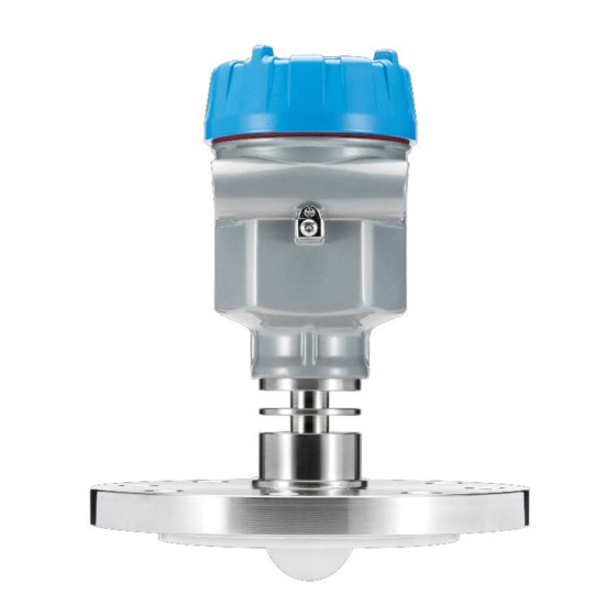
Introduction 1.1 Overview The SLN 700 SmartLine 80 GHz Non-Contact Radar transmitter is an electronic instrument designed to measure levels of liquid and solid materials. Non-Contact Radar (NCR) transmitters use Frequency Modulated Continuous Wave (FMCW) radar signals that are reflected by the material to be measured. -
Page 10: Electronics
Electronics The Electronics consists of 2 distinct modules; core measurement electronics module and an optional display module. Both are replaceable in the field. To make changes to the transmitter setup or configuration without the use of an external device such as a handheld or PC, an optional 4-Button interface is available. The Optional Display module has the following features. -
Page 11: Communicating With The Transmitter
1.4 Communicating with the Transmitter Level monitoring is possible through either the analog current (4-20 mA) or HART. It is possible © to configure a transmitter using HART protocol or using the four-button interface and display. Refer to manual 34-SL-25-16, SLN700 NCR HART Option Manual for details on available HART commands 1.5 SLN 700 Transmitter Label The transmitter label is mounted on the side of the electronics housing... -
Page 12: Transmitter Model Number Description
1.6 Transmitter Model Number Description The model number is comprised from a number of selections and options that can be specified when ordering the transmitter. It includes a basic transmitter type such as SLN720 (standard temperature, standard pressure) followed by a maximum of nine additional character strings that can be selected from a corresponding Table in the Model Selection Guide (MSG). -
Page 13: Radar Level Measurement
Radar Level Measurement 2.1 Overview This chapter describes the theory of operation of the transmitter and discusses how measurements are affected by tank and process conditions. 2.2 Theory of Operation The fundamental principle of operation is level measurement through the reflection of frequency modulated radar waves (FMCW technique). -
Page 14: Mounting
Mounting Due to the finite beam angle and resulting transmission cone, there should be no obstacles in the area radiated by the transmitted microwave beam from the lower edge of the antenna to the material surface to be measured. Therefore, it is necessary to avoid these facilities in the tank during installation. These include ladders, limit switches, heating equipment, supports, etc. -
Page 15: Moisture-Proof
Moisture-proof For instruments that are installed outside, in a wet environment, and cooling or heating tanks, the cable gland must be tightened. The cable, at the cable gland entry, must be bent downward to prevent moisture as shown in Figure 3-2. Figure 3-2: Moisture-proof diagram Revision 1 SLN 700 SmartLine NCR Level Transmitter User’s Manual... -
Page 16: Installation Position
Installation position During the installation, please note that the instrument should be kept minimal distance to tank wall from the vessel wall. For different antenna, please refer to Table 3-1. However, the instrument must not under any circumstances be mounted closer than 200mm to the vessel wall or values calculated from Table 3-1. -
Page 17: Figure 3-4: Conical Vessel Installation
For the conical vessel with a flat tank top, the best installation position of instrument is the top center of the vessel, which ensures that the bottom of the container is measured. Figure 3-4: Conical vessel installation Revision 1 SLN 700 SmartLine NCR Level Transmitter User’s Manual Page 9... -
Page 18: Nozzle Installations
Nozzle installations In the case of a material with good reflection properties (high dielectric constant, DK), the sensor may be mounted on a nozzle. The background subtraction ("virtual echo learning") feature can further reduce false echoes from nozzle openings. Table 3-2 shows detail of the size limitations of the nozzle. -
Page 19: Correct And Incorrect Installation Position
Correct and incorrect Installation position 1. Correct 2. Incorrect: Instruments are installed in the arched or round top of the tank, which will result in multiple echoes. This should be avoided as much as possible during the installation. Figure 3-6: Correct and incorrect installation position 1. -
Page 20: Installations With Agitation
This will eliminate the influence of false echo generated by mixing blades. If foam or wave is generated due to agitation, then the customer should consider a guided wave radar sensor such as the Honeywell SLG-700 series. Go to https://www.honeywellprocess.com/en-US/explore/products/instrumentation/process-... -
Page 21: Transmitter Installation
Transmitter Installation Supply voltage (4-20) mA / HART (2-Wire Power supply and the output current signal are carried by the same two-core cable. The allowed supply voltage range is 12V to 30Vdepending on loop resistance. There must always be between 12V and 30V on the transmitter terminals, regardless of loop current. A safety barrier (refer to Table 3-1 for detailed specification) must be placed between the power supply and... -
Page 22: Installation Of Connecting Cables
Installation of connecting cables General introduction 4-20 mA / HART (2-Wire) A regular two conductor cable can be used as the power supply cable, and the outside diameter of the cable should be (5-9) mm to ensure the sealing of cable entry. In case of potential electromagnetic interference, it is recommended to use a shielded cable. -
Page 23: Hazardous Location - Intrinsic Safety
Hazardous Location – Intrinsic Safety The hazardous location approved models of the product include intrinsically safe version. The working ambient temperature of the transmitter is (-25~80 ° C). Under normal or fault conditions, the max temperature at any part of the surface will not exceed the values according Table 4-4. -
Page 24: Figure 4-3: Intrinsically Safe Wiring
Figure 4-3: Intrinsically Safe Wiring WARNING: Special Conditions for safe use: • Electrical connections and IS input parameters should be observed in accordance with Ex instruction • WARNING – Potential Electrostatic Charging Hazard • When the enclosure is made of aluminum alloy, impact or friction should be avoid to Control the mechanical spark •... -
Page 25: Operating The Transmitter
Operating the Transmitter 5.1 Functions of keys There are 4 keys on the instrument panel, which can be used to operate the instrument. After setup, the measurement value is displayed on the LCD screen and can be read out clearly through the glass window. - Page 26 Programming The four keys on the panel can be used to set parameters, debug and instruction test the instrument, etc. Programming The menu structure can be seen in Table 5-2 Table 5-3. menu structure The rightward transition to the horizontal arrow in the figure can be achieved by the key;...
- Page 27 Programming menu description 1 Basic Settings The basic settings include the settings of main instrument parameters, such as measuring range, material properties, etc. Press in the running state to enter the programming state, and the LCD will display the main menu. Basic settings Display Diagnostics...
- Page 28 1.3 Near If the tank contains obstacles between the sensor reference plane and blanking the maximum height of the material, a near blanking distance can be set to avoid false echo detection. When displaying the menu number 1.2, press key to enter the near blanking setting menu.
- Page 29 1.6 Maximum Maximum Adjustment is used to set the gauge output when the level Adjustment is closest to the reference plane (highest liquid level). Together with Minimum Adjustment, it determines the proportion of linear correspondence of current output. Display in LCD is as follows. When the menu number is 1.5, press key to enter the maximum adjustment.
- Page 30 2 Display This feature is used for display programming. When displaying the main menu, press key to move the arrow to the display item. Display in LCD is as follows. Basic settings Display Diagnostics Advanced Settings Press to enter display mode programming. 2.1 Display Enter display mode programming.
- Page 31 3 Diagnostics Basic settings Display Diagnostics Advanced Settings System Diagnostics is used to test and debug the instrument and its components. Press to enter the diagnostic function 3.1 Choose When the LCD displays menu number 3, press key to enter the Curve echo curve display function.
- Page 32 False Echo: The "False Echo" shows the false signal strength in dB of the obstruction reflections over the range specified by the user. The signal records an envelope of the false signal of the measurement (for example, the reflected signal from ladder of tank). When the LCD displays menu number 3.1, press key.
- Page 33 3.3 Sensor Press key to enter the next diagnostics measurement status when Status the LCD displays menu number 3.2. Operation status of the sensor is as follows. Sensor Status Volt Service Time T is current sensor temperature in ‘C; DB is current signal strength in Db; Volt is current power input voltage;...
- Page 34 4 Advanced The advanced settings menu includes more specialized features for use Settings by trained personnel. There are mainly false echo learning, reset and instrument parameter storage, etc. When the LCD displays the main menu, press key to move the arrow to the service item. Display in LCD is as follows.
- Page 35 4.3 Reset to Reset function is used to revert the instrument parameters back to the Factory initial factory settings. When displaying the current output (menu Settings number 4.2), press key to enter the reset function. Display in LCD is as follows. Factory Settings Press to enter the reset menu and select reset for factory settings.
- Page 36 4.7 Envelope Envelope Level Level Device will only read signal strength above Envelop level. Default envelop level DB value is 5. User can set different value by referring to EFF curve based on site situation. See Figure 5-2 for the definition of this parameter. 4.8 Hart When two or more instruments use the HART communication interface Address and...
- Page 37 4.9 Damp When the LCD menu number is 4.9, press key to enter the damp Time time setting menu. Display in LCD is as follows. Damp time To damp process-dependent measured value fluctuations, set an integration time of 1 … 20 s in this menu item. Default setting is 8. Press to enter the status of parameter editing.
- Page 38 4.20 Low DK When the LCD displays 4.20, press to enter the DK value adjustment setting menu. Display in LCD is as follows. Low DK Distance Press again to enter the DK value adjustment menu. Low DK Press key to select “Yes”, used for the measuring setting when DK value is low (<=2.1)..
- Page 39 5 System The system menu contains basic information about the meter production, such as Info, Software Version, Latching Mode, Write Protect, etc. When the LCD displays the main menu, press key to move the arrow to the information item. Display in LCD is as follows.
-
Page 40: Table 5-2: Display Menu Tree Basic Settings, Display And Diagnostics
Table 5-2: Display Menu Tree Basic Settings, Display and Diagnostics Level 1 / Level 2 / Menu no. Level 3 Level 4 Level 5 Menu no Rapid Material Change First Echo Normal Small Liquid Bigger Biggest Surface Wave Low DK Rapid 1.1 Medium Material... - Page 41 Level 1 / Level 2 / Menu no. Level 3 Level 4 Level 5 Menu no 2.1 Display Value Distance / Height / Percent 2. Display 2.2 Language Chinese / English 3.1 Choose Curve Eff Curve / Echo Curve / False Echo / Log curve 3.2 Start Simulation Current/Distance...
-
Page 42: Table 5-3: Display Menu Tree Advanced Settings And System
Table 5-3: Display Menu Tree Advanced Settings and System Level 1 / Level 2 / Menu no. Level 3 Menu no 4.1 False Echo Memory 4.2 Failure Mode No Change/21.5 mA/22.0 mA/3.6 mA 4.3 Reset to Factory Settings Y / N 4.4 Distance Adjust 4.5 Echo Threshold 4.7 Envelope Level... -
Page 43: Figure 5-2: Representation Of An Echo Curve Defining The Echo Threshold And The Envelope Offset
Figure 5-2: Representation of an echo curve defining the Echo Threshold and the Envelope Offset quantities. Revision 1 SLN 700 SmartLine NCR Level Transmitter User’s Manual Page 35... -
Page 44: Maintenance
Maintenance 6.1 Configuration method There are three debugging methods for SLN 700 1. Display/configuration module 2. Host PC 3. HART hand-held programmer Configuration with Display Display modular is a pluggable display/configuration tool. The configuration can be done through operating with 4 buttons on Display. The language for the configuration menu is optional. -
Page 45: Configuration
Configuration 3 250 Ω 1 HART handheld programmer 2 SLN700 level gauge Figure 6-1: Connect via HART hand-held Revision 1 SLN 700 SmartLine Non-Contact Radar User’s Manual... -
Page 46: Procedures
6.2 Procedures Output Check Procedures The Output Check has the following procedures: • The Loop Test procedure checks for continuity and the condition of components in the output current loop. • The Trim DAC Current procedure calibrates the output of the Digital-to-Analog converter for minimum (0%) and maximum (100%) values of 4 mA and 20 mA, respectively. -
Page 47: Error Codes
Error Codes: Following are the details of error codes with respective resolution. The error codes will show up on display screen during malfunction/error condition in device Error Description Solutions Code Communication error between display Need new display module and module EEPROM Error Return to Factory PLL Failed, RF circuit failure... -
Page 48: Glossary
Glossary Accuracy: The closeness of the agreement between the result of the measurement and the true value of the quantity. Accuracy should not be confused with precision which relates to agreement between subsequent measurements. The quoted accuracy depends on the initial characterization, the reproducibility of the standard, and the stability of the measurement between calibrations. - Page 49 4-20 mA analog instrumentation wiring Honeywell Experion: An advanced distributed control system (DCS) and innovative software applications to improve users' business performance and ensures reliable performance. Honeywell Field Device Manager (FDM): A centralized asset management system for remote configuration and maintenance of smart field devices based on HART, PROFIBUS and Fieldbus FOUNDATION protocols.
- Page 50 Latching Mode: A parameter in the Level transmitter Advanced Display which allows for the selection of the behavior of the Level transmitter in the event of a critical error. In this mode, the transmitter wills stay in the critical error state until a user performs a hardware or software reset.
- Page 51 Safety Instrumented Function (SIF): A set of equipment intended to reduce the risk due to a specific hazard (a safety loop). Safety Integrity Level (SIL): A discrete level (one out of a possible four) for specifying the safety integrity requirements of the safety functions to be allocated to the E/E/PE safety- related systems where Safety Integrity Level 4 has the highest level of safety integrity and Safety Integrity Level 1 has the lowest.
- Page 52 Index About This Manual ............iii Process Connector............2 Agitation ............... 12 Programming instruction ..........18 Antenna extension ............10 Programming menu structure ........18 Communicating with the Transmitter ......3 Radar Level Measurement ..........5 Connecting cables ............14 Agitation ..............
- Page 53 Phone: (86-21) 5257-4568 Fax: (86-21) 6237-2826 Singapore Honeywell Pte Ltd. Phone: +(65) 6580 3278 Fax: +(65) 6445-3033 South Korea Honeywell Korea Co Ltd Phone: +(822) 799 6114 Fax: +(822) 792 9015 Revision 1 SLN 700 SmartLine Non-Contact Radar User’s Manual...
- Page 54 For more information To learn more about SmartLine Transmitters, visit www.honeywellprocess.com Or contact your Honeywell Account Manager Process Solutions Honeywell 1250 W Sam Houston Pkwy S Houston, USA, TX 77042 Honeywell Control Systems Ltd Honeywell House, Skimped Hill Lane Bracknell, England, RG12 1EB...