Endress+Hauser PROline promag 53 Operating Instructions Manual
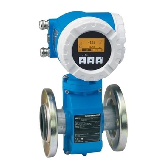
Electromagnetic flow measuring system
Hide thumbs
Also See for PROline promag 53:
- Operating manual (191 pages) ,
- Operating instructions manual (177 pages) ,
- Documentation (108 pages)
Table of Contents

Related Manuals for Endress+Hauser PROline promag 53


Summary of Contents for Endress+Hauser PROline promag 53
- Page 1 BA 047D/24/ae/06.01 P R O l i n e p r o m a g 5 3 50103789 E l e c t r o m a g n e t i c Valid as of software version: V 1.02.XX (amplifier) V 1.02.XX (communication) F l o w M e a s u r i n g S y s t e m O p e r a t i n g I n s t r u c t i o n s...
- Page 2 The routine takes you directly to the cause of the problem and the appropriate remedial measures. Returning devices If you return a measuring device to Endress+Hauser for repair or calibration, you must obtain a Return Authorization number. See Return Authorization Policy at the back of this manual.
- Page 3 “ Q U I C K S E T U P ” c o m m i s s i o n i n g “ Q U I C K S E T U P ” c o m m i s s i o n i n g 1002 ENDRESS+HAUSER Quick Setup Commission...
- Page 4 “ Q U I C K S E T U P ” c o m m i s s i o n i n g P R O l i n e P r o m a g 5 3 E n d r e s s + H a u s e r...
-
Page 5: Table Of Contents
P R O l i n e P r o m a g 5 3 ......O p e r a t i o n C o n t e n t s Display and operating elements . - Page 6 P R O l i n e P r o m a g 5 3 10.1.4 Output ......122 10.1.5 Power supply .
-
Page 7: A F E T Y I N S T R U C T I O N S
Strict compliance with the instructions in the Operating Manual is mandatory. • Endress+Hauser will be happy to assist in clarifying the chemical resistance proper- ties of parts wetted by special fluids, including fluids used for cleaning. • If welding work is performed on the piping system, do not ground the welding appli- ance through the Promag flowmeter. -
Page 8: Return
The following procedures must be carried out before a flowmeter requiring repair or calibration, for example, is returned to Endress+Hauser: • Always follow the Return Authorization Policy. Only then can Endress+Hauser trans- port, examine and repair a returned device. • Enclose special handling instructions if necessary, for example a safety data sheet as per EN 91/155/EEC. -
Page 9: 2 I D E N T I F I C A T I O N
2 . 1 . 1 N a m e p l a t e o f t h e t r a n s m i t t e r ENDRESS+HAUSER PROMAG XXXXX-XXXXXXXXXXXX IP67/NEMA/Type4X... -
Page 10: Nameplate Of The Sensor
Laboratory Procedures”. The measuring system described in this Operating Manual is therefore in conformity with the statutory requirements of the EC Directives. Endress+Hauser confirms suc- cessful testing of the device by affixing to it the CE mark. E n d r e s s + H a u s e r... -
Page 11: Registered Trademarks
HART is a registered trademark of HART Communication Foundation, Austin, USA S-DAT™, T-DAT™, F-Chip™, FieldTool™, FieldCheck™, Applicator™ are registered trademarks of Endress+Hauser Flowtec AG, Reinach, CH E n d r e s s + H a u s e r... - Page 12 2 I d e n t i f i c a t i o n P R O l i n e P r o m a g 5 3 E n d r e s s + H a u s e r...
-
Page 13: I N S T A L L A T I O N
P R O l i n e P r o m a g 5 3 3 I n s t a l l a t i o n I n s t a l l a t i o n 3 . -
Page 14: Storage
3 I n s t a l l a t i o n P R O l i n e P r o m a g 5 3 Transporting flanged devices (D ≥ 14" / DN ≥ 350): Use only the metal eyes on the flanges for transporting the device, lifting it and position- ing the sensor in the piping. -
Page 15: Installation Conditions
P R O l i n e P r o m a g 5 3 3 I n s t a l l a t i o n 3 . 2 I n s t a l l a t i o n c o n d i t i o n s 3 . - Page 16 3 I n s t a l l a t i o n P R O l i n e P r o m a g 5 3 P a r t i a l l y f i l l e d p i p e s Partially filled pipes with gradients necessitate a drain-type configuration.
-
Page 17: Orientation
P R O l i n e P r o m a g 5 3 3 I n s t a l l a t i o n 3 . 2 . 3 O r i e n t a t i o n An optimum orientation position helps avoid gas and air accumulations and deposits in the measuring tube. -
Page 18: Vibrations
3 I n s t a l l a t i o n P R O l i n e P r o m a g 5 3 I n l e t a n d o u t l e t r u n s If possible, install the sensor well clear of fittings such as valves, T-pieces, elbows, etc. -
Page 19: Foundations, Supports
P R O l i n e P r o m a g 5 3 3 I n s t a l l a t i o n 3 . 2 . 5 F o u n d a t i o n s , s u p p o r t s If the nominal diameter is ≥... -
Page 20: Adapters
No pressure loss if the sensor is installed in a pipe of the same nominal diameter. Pres- sure losses occur in configurations incorporating adapters (reducers, expanders). Con- tact your Endress+Hauser representative or Endress+Hauser for information. 3 . 2 . 7 N o m i n a l d i a m e t e r a n d f l o w r a t e The diameter of the pipe and the flow rate determine the nominal diameter of the sensor. - Page 21 P R O l i n e P r o m a g 5 3 3 I n s t a l l a t i o n P r o m a g W Flow rate characteristic values - Promag W (SI units) Nominal Recommended Factory settings...
- Page 22 3 I n s t a l l a t i o n P R O l i n e P r o m a g 5 3 Flow rate characteristic values - Promag W (US units) Nominal diameter Recommended Factory setting flow rate min./max.
- Page 23 P R O l i n e P r o m a g 5 3 3 I n s t a l l a t i o n P r o m a g P Flow rate characteristic values - Promag P (SI units) Nominal Recommended Factory settings...
- Page 24 3 I n s t a l l a t i o n P R O l i n e P r o m a g 5 3 Flow rate characteristic values - Promag P (US units) Nominal diameter Recommended Factory setting flow rate min./max.
-
Page 25: Length Of Connecting Cable
P R O l i n e P r o m a g 5 3 3 I n s t a l l a t i o n Flow rate characteristic values - Promag H (US units) Nominal diameter Recommended Factory settings flow rate min./max. -
Page 26: Installation Instruction
3 I n s t a l l a t i o n P R O l i n e P r o m a g 5 3 3 . 3 I n s t a l l a t i o n i n s t r u c t i o n 3 . - Page 27 P R O l i n e P r o m a g 5 3 3 I n s t a l l a t i o n A s s e m b l y w i t h g r o u n d d i s k s ( 1 " t o 1 2 " / D N 2 5 t o 3 0 0 ) Depending on the application, e.g.
- Page 28 3 I n s t a l l a t i o n P R O l i n e P r o m a g 5 3 S c r e w t i g h t e n i n g t o r q u e s ( P r o m a g W ) Note the following points: •...
- Page 29 P R O l i n e P r o m a g 5 3 3 I n s t a l l a t i o n Promag W Threaded Max. tightening torque [Nm] Nominal diameter Pressure rating fasteners [mm] [bar] Hard rubber...
- Page 30 3 I n s t a l l a t i o n P R O l i n e P r o m a g 5 3 Promag W AWWA Threaded Max. tightening torque ft-lb (Nm) Nominal diameter Pressure rating fasteners [mm] [inch]...
- Page 31 P R O l i n e P r o m a g 5 3 3 I n s t a l l a t i o n Promag W Threaded Max. tightening torque [Nm] Nominal diameter Pressure rating fasteners [mm] Hard rubber Polyurethane...
-
Page 32: Installing The Promag P Sensor
3 I n s t a l l a t i o n P R O l i n e P r o m a g 5 3 3 . 3 . 2 I n s t a l l i n g t h e P r o m a g P s e n s o r "... - Page 33 P R O l i n e P r o m a g 5 3 3 I n s t a l l a t i o n A s s e m b l y w i t h g r o u n d d i s k s ( 1 / 2 " t o 1 2 " / D N 1 5 t o 3 0 0 ) Depending on the application, e.g.
- Page 34 3 I n s t a l l a t i o n P R O l i n e P r o m a g 5 3 I n s t a l l i n g t h e h i g h - t e m p e r a t u r e v e r s i o n ( w i t h P F A l i n i n g ) The high-temperature version has a housing support for the thermal separation of sensor and transmitter.
- Page 35 P R O l i n e P r o m a g 5 3 3 I n s t a l l a t i o n T i g h t e n i n g t o r q u e s f o r t h r e a d e d f a s t e n e r s ( P r o m a g P ) Note the following points: •...
- Page 36 3 I n s t a l l a t i o n P R O l i n e P r o m a g 5 3 Promag P Threaded Max. tightening torque [Nm] Nominal diameter Pressure rating fasteners [mm] [bar] PTFE...
- Page 37 P R O l i n e P r o m a g 5 3 3 I n s t a l l a t i o n Promag P Threaded Max. tightening torque [Nm] Nominal diameter Pressure rating fasteners [mm] PTFE −...
-
Page 38: Installing The Promag H Sensor
3 I n s t a l l a t i o n P R O l i n e P r o m a g 5 3 3 . 3 . 3 I n s t a l l i n g t h e P r o m a g H s e n s o r The Promag H is supplied to order, with or without pre-installed process connections. - Page 39 P R O l i n e P r o m a g 5 3 3 I n s t a l l a t i o n U s a g e a n d a s s e m b l y o f g r o u n d r i n g s ( 1 / 1 2 " t o 1 " / D N 2 t o 2 5 ) In case the process connections are made of plastic (e.g.
- Page 40 3 I n s t a l l a t i o n P R O l i n e P r o m a g 5 3 W e l d i n g t h e s e n s o r i n t o t h e p i p i n g ( w e l d n i p p l e s ) "...
-
Page 41: Turning The Transmitter Housing
P R O l i n e P r o m a g 5 3 3 I n s t a l l a t i o n 3 . 3 . 4 T u r n i n g t h e t r a n s m i t t e r h o u s i n g T u r n i n g t h e a l u m i n u m f i e l d h o u s i n g Warning: The turning mechanism in devices with EEx d/de or FM/CSA Cl. -
Page 42: Turning The Local Display
3 I n s t a l l a t i o n P R O l i n e P r o m a g 5 3 3 . 3 . 5 T u r n i n g t h e l o c a l d i s p l a y Remove the cover of the electronics compartment. -
Page 43: Installing The Wall-Mount Transmitter
P R O l i n e P r o m a g 5 3 3 I n s t a l l a t i o n 3 . 3 . 6 I n s t a l l i n g t h e w a l l - m o u n t t r a n s m i t t e r h o u s i n g There are various ways of installing the wall-mount transmitter housing: •... - Page 44 3 I n s t a l l a t i o n P R O l i n e P r o m a g 5 3 P a n e l i n s t a l l a t i o n Prepare the opening in the panel (Fig.
-
Page 45: Installation Check
P R O l i n e P r o m a g 5 3 3 I n s t a l l a t i o n 3 . 4 I n s t a l l a t i o n c h e c k Perform the following checks after installing the measuring device in the pipe: Device condition and specifications Notes... - Page 46 3 I n s t a l l a t i o n P R O l i n e P r o m a g 5 3 E n d r e s s + H a u s e r...
-
Page 47: W I R I N G
P R O l i n e P r o m a g 5 3 4 W i r i n g W i r i n g Warning: • When connecting Ex-certified devices, see the notes and diagrams in the Ex-specific supplement to this Operating Manual. - Page 48 4 W i r i n g P R O l i n e P r o m a g 5 3 Fig. 28: Connecting the remote version of Promag W/P a = cover of the connection compartment, b = cover of the sensor connection housing, c = signal cable, d = coil current cable, n.c.
- Page 49 P R O l i n e P r o m a g 5 3 4 W i r i n g Cable termination for the remote version Promag W / Promag P Terminate the signal and coil current cables as shown in the figure below (Detail A). Fit the fine-wire cores with cable end sleeves (Detail B).
- Page 50 4 W i r i n g P R O l i n e P r o m a g 5 3 Cable termination for the remote version Promag H Terminate the signal and coil current cables as shown in the figure below (Detail A). Fit the fine-wire cores with cable end sleeves (Detail B).
-
Page 51: Cable Specifications
P R O l i n e P r o m a g 5 3 4 W i r i n g 4 . 1 . 2 C a b l e s p e c i f i c a t i o n s Coil cable •... -
Page 52: Connecting The Measuring Unit
4 W i r i n g P R O l i n e P r o m a g 5 3 4 . 2 C o n n e c t i n g t h e m e a s u r i n g u n i t 4 . - Page 53 P R O l i n e P r o m a g 5 3 4 W i r i n g – 27 + 26 – 25 + 24 – 23 + 22 – 21 + 20 N (L-) L1 (L+) Fig.
-
Page 54: Terminal Assignment
4 W i r i n g P R O l i n e P r o m a g 5 3 4 . 2 . 2 T e r m i n a l a s s i g n m e n t Terminal No. -
Page 55: Hart Connection
P R O l i n e P r o m a g 5 3 4 W i r i n g 4 . 2 . 3 H A R T c o n n e c t i o n Users have the following connection options at their disposal: •... -
Page 56: Potential Equalization
4 W i r i n g P R O l i n e P r o m a g 5 3 4 . 3 P o t e n t i a l e q u a l i z a t i o n 4 . -
Page 57: Special Cases
P R O l i n e P r o m a g 5 3 4 W i r i n g 4 . 3 . 2 S p e c i a l c a s e s M e t a l , u n g r o u n d e d p i p i n g In order to prevent outside influences on measurement, it is advisable to use ground cables to connect each sensor flange to its corresponding pipe flange and ground the flanges. - Page 58 4 W i r i n g P R O l i n e P r o m a g 5 3 P l a s t i c p i p e s a n d i s o l a t i n g l i n e d p i p e s Normally, potential is matched using the reference electrodes in the measuring tube.
-
Page 59: Degree Of Protection
Caution: Do not loosen the threaded fasteners of the Promag sensor housing, as otherwise the degree of protection guaranteed by Endress+Hauser no longer applies. Note: The Promag W and Promag P sensors can be supplied with NEMA 6P (IP 68) rating (permanent immersion in water to a depth of 10 ft/3 meters). -
Page 60: Electrical Connection Check
4 W i r i n g P R O l i n e P r o m a g 5 3 4 . 5 E l e c t r i c a l c o n n e c t i o n c h e c k Perform the following checks after completing electrical installation of the measuring device: Device condition and specifications... -
Page 61: O P E R A T I O
P R O l i n e P r o m a g 5 3 5 O p e r a t i o n O p e r a t i o n 5 . 1 D i s p l a y a n d o p e r a t i n g e l e m e n t s The local display enables you to read all important parameters directly at the measuring point and configure the device using the “Quick Setup”... - Page 62 5 O p e r a t i o n P R O l i n e P r o m a g 5 3 D i s p l a y ( o p e r a t i o n m o d e ) The display area consists of three lines in all;...
- Page 63 P R O l i n e P r o m a g 5 3 5 O p e r a t i o n I c o n s The icons which appear in the field on the left make it easier to read and recognize measured variables, device status, and error messages.
- Page 64 5 O p e r a t i o n P R O l i n e P r o m a g 5 3 C o n t r o l l i n g t h e b a t c h i n g p r o c e s s e s u s i n g t h e l o c a l d i s p l a y With measuring instruments with suitable software, you can carry out batching proc- esses directly using the local display.
-
Page 65: Brief Operating Instruction To The Function Matrix
P R O l i n e P r o m a g 5 3 5 O p e r a t i o n 5 . 2 B r i e f o p e r a t i n g i n s t r u c t i o n t o t h e f u n c t i o n m a t r i x Note: •... -
Page 66: General Notes
There is no need to change these parameters under normal circumstances and conse- quently, they are protected by a special code known only to the E+H service organiza- tion. Please contact Endress+Hauser if you have any questions. 5 . 2 . 3... -
Page 67: Error Messages
P R O l i n e P r o m a g 5 3 5 O p e r a t i o n 5 . 3 E r r o r m e s s a g e s T y p e o f e r r o r Errors which occur during commissioning or measuring operation are displayed imme- diately. -
Page 68: Communication (Hart)
P R O l i n e P r o m a g 5 3 5 O p e r a t i o n C o n f i r m i n g e r r o r m e s s a g e s For the sake of plant and process safety, the measuring device can be configured in such a way that fault messages ( $) always have to be rectified and acknowledged locally by pressing F . -
Page 69: Operating Options
P R O l i n e P r o m a g 5 3 5 O p e r a t i o n 5 . 4 . 1 O p e r a t i n g o p t i o n s For the complete operation of the field device, including device-specific commands, there are Device Description (DD) files available to the user to provide the following operating aids and programs:... -
Page 70: Device And Process Variables
5 O p e r a t i o n P R O l i n e P r o m a g 5 3 5 . 4 . 2 D e v i c e a n d p r o c e s s v a r i a b l e s Device variables: The following device variables are available using the HART protocol: Code (decimal) - Page 71 P R O l i n e P r o m a g 5 3 5 O p e r a t i o n Command No. Command data Response data HART command / Access type (numeric data in decimal form) (numeric data in decimal form) Read primary process none...
- Page 72 5 O p e r a t i o n P R O l i n e P r o m a g 5 3 Command No. Command data Response data HART command / Access type (numeric data in decimal form) (numeric data in decimal form) Set HART shortform address Byte 0: desired address (0 - 15)
- Page 73 P R O l i n e P r o m a g 5 3 5 O p e r a t i o n Command No. Command data Response data HART command / Access type (numeric data in decimal form) (numeric data in decimal form) Read output information of none...
- Page 74 5 O p e r a t i o n P R O l i n e P r o m a g 5 3 Command No. Command data Response data HART command / Access type (numeric data in decimal form) (numeric data in decimal form) Common Practice Commands Write damping value for...
- Page 75 P R O l i n e P r o m a g 5 3 5 O p e r a t i o n Command No. Command data Response data HART command / Access type (numeric data in decimal form) (numeric data in decimal form) Write unit of primary process Set unit of primary process variable.
- Page 76 5 O p e r a t i o n P R O l i n e P r o m a g 5 3 Command No. Command data Response data HART command / Access type (numeric data in decimal form) (numeric data in decimal form) Write assignments of the Setting of the device variables to the four...
-
Page 77: Device Status / Error Messages
P R O l i n e P r o m a g 5 3 5 O p e r a t i o n D e v i c e s t a t u s / E r r o r m e s s a g e s 5 . - Page 78 5 O p e r a t i o n P R O l i n e P r o m a g 5 3 Short error description ( → Page 100 ) Byte Error No. not assigned – not assigned –...
- Page 79 P R O l i n e P r o m a g 5 3 5 O p e r a t i o n Short error description ( → Page 100 ) Byte Error No. not assigned – not assigned –...
- Page 80 5 O p e r a t i o n P R O l i n e P r o m a g 5 3 Short error description ( → Page 100 ) Byte Error No. not assigned – not assigned –...
- Page 81 P R O l i n e P r o m a g 5 3 5 O p e r a t i o n Short error description ( → Page 100 ) Byte Error No. Simulation status input active Simulation status input active Simulation status input active Simulation of response to error (outputs) active...
-
Page 82: Switching Hart Write Protection
5 O p e r a t i o n P R O l i n e P r o m a g 5 3 5 . 4 . 5 S w i t c h i n g H A R T w r i t e p r o t e c t i o n o n a n d o f f A jumper on the I/O board provides the means of activating or deactivating HART write protection. -
Page 83: C O M M I S S I O N I N
P R O l i n e P r o m a g 5 3 6 C o m m i s s i o n i n g C o m m i s s i o n i n g 6 . -
Page 84: " C O M M I S S I O N I N G " Q U I C K S E T U P M E N U
“ C o m m i s s i o n i n g ” Q u i c k S e t u p m e n u This Quick Setup menu guides you systematically through the setup procedure for all the major device functions that have to be configured for standard measuring operation. 1002 ENDRESS+HAUSER Quick Setup Commission 2000... -
Page 85: Pulsating Flow" Quick Setup Menu
P R O l i n e P r o m a g 5 3 6 C o m m i s s i o n i n g 6 . 2 . 3 “ P u l s a t i n g F l o w ” Q u i c k S e t u p m e n u Certain types of pumps such as reciprocating, peristaltic and cam-type pumps, for example, create a flow characterized by severe periodic fluctuations (Fig. - Page 86 This Quick Setup menu guides you systematically through the setup procedure for all the device functions that have to be configured for measuring pulsating flows. Note that this has no effect on the original signal values such as measuring range, current range or limit value! ENDRESS+HAUSER 1003 Quick Setup Puls. Flow...
- Page 87 P R O l i n e P r o m a g 5 3 6 C o m m i s s i o n i n g “Pulsating flow” Quick Setup menu HOME position → F → MEASURED VARIABLE (A) MEASURED VARIABLE →...
-
Page 88: Batching" Quick Setup
6 C o m m i s s i o n i n g P R O l i n e P r o m a g 5 3 6 . 2 . 4 “ B a t c h i n g ” Q u i c k S e t u p This Quick Setup menu guides you systematically through the setup procedure for all the device functions that have to be parameterized and configured for batching opera- tion. - Page 89 P R O l i n e P r o m a g 5 3 6 C o m m i s s i o n i n g ENDRESS+HAUSER Quick Setup HOME-POSITION 1005 Batching/Dosing ON-Value 6402 Low flow cut off...
- Page 90 6 C o m m i s s i o n i n g P R O l i n e P r o m a g 5 3 “Batching” Quick Setup menu HOME position → F → MEASURED VARIABLE (A) MEASURED VARIABLE →...
-
Page 91: Empty-Pipe/Full-Pipe Calibration
P R O l i n e P r o m a g 5 3 6 C o m m i s s i o n i n g 6 . 2 . 5 E m p t y - p i p e / f u l l - p i p e c a l i b r a t i o n Flow cannot be measured correctly unless the measuring tube is full. -
Page 92: Current Output: Active/Passive
6 C o m m i s s i o n i n g P R O l i n e P r o m a g 5 3 6 . 2 . 6 C u r r e n t o u t p u t : a c t i v e / p a s s i v e The current outputs can be configured as “active”... -
Page 93: Relay Contacts: Normally Closed/Normally Open
P R O l i n e P r o m a g 5 3 6 C o m m i s s i o n i n g 6 . 2 . 7 R e l a y c o n t a c t s : N o r m a l l y c l o s e d / n o r m a l l y o p e n The relay contact can be configured as normally open (NO or make) or normally closed (NC or break) contacts by means of two jumpers on the relay submodule. -
Page 94: Data Storage Device (Dat, F-Chip™)
6 C o m m i s s i o n i n g P R O l i n e P r o m a g 5 3 6 . 3 D a t a s t o r a g e d e v i c e ( D A T , F - C h i p ™ ) S - D A T ™... - Page 95 P R O l i n e P r o m a g 5 3 7 M a i n t e n a n c e M a i n t e n a n c e The Promag 53 flow measuring system requires no special maintenance. E x t e r i o r c l e a n i n g When cleaning the exterior of measuring devices, always use cleaning agents that do not attack the surface of the housing and the seals.
- Page 96 7 M a i n t e n a n c e P R O l i n e P r o m a g 5 3 E n d r e s s + H a u s e r...
-
Page 97: A C C E S S O R I E
8 A c c e s s o r i e s A c c e s s o r i e s Various accessories, which can be ordered separately from Endress+Hauser, are avail- able for the transmitter and the sensor. The E+H service organization can provide detailed information on the order codes of your choice. -
Page 98: T R O U B L E S H O O T I N
8 A c c e s s o r i e s P R O l i n e P r o m a g 5 3 Accessory Description Ordering code DK5HR − * * * * Ground rings for If the process connections are made of PVC Promag H or PVDF, ground rings are necessary to... -
Page 99: Troubleshooting Instructions
P R O l i n e P r o m a g 5 3 9 T r o u b l e s h o o t i n g T r o u b l e s h o o t i n g 9 . -
Page 100: System Error Messages
In the event of a serious fault, a flowmeter might have to be returned to the manufacturer for repair. The procedures on Page 8 must be carried out before you return a flowmeter to Endress+Hauser. Always follow the Return Authorization Policy. You will find this policy at the back of this manual. - Page 101 P R O l i n e P r o m a g 5 3 9 T r o u b l e s h o o t i n g Type Error message / No. Cause Remedy / spare part SENSOR SW DAT Sensor: 1.
- Page 102 9 T r o u b l e s h o o t i n g P R O l i n e P r o m a g 5 3 Type Error message / No. Cause Remedy / spare part A / C COMPATIB.
- Page 103 P R O l i n e P r o m a g 5 3 9 T r o u b l e s h o o t i n g Type Error message / No. Cause Remedy / spare part STACK PULS The temporarily buffered flow 1.
- Page 104 9 T r o u b l e s h o o t i n g P R O l i n e P r o m a g 5 3 Type Error message / No. Cause Remedy / spare part Nr.
-
Page 105: Process Error Messages
P R O l i n e P r o m a g 5 3 9 T r o u b l e s h o o t i n g 9 . 3 P r o c e s s e r r o r m e s s a g e s Process errors can be defined as either “Fault”... - Page 106 9 T r o u b l e s h o o t i n g P R O l i n e P r o m a g 5 3 Type Error message / No. Cause Remedy PROGRESS NOTE End of filling process approach- No measures required (if neces- # 473...
-
Page 107: Process Errors Without Message
P R O l i n e P r o m a g 5 3 9 T r o u b l e s h o o t i n g 9 . 4 P r o c e s s e r r o r s w i t h o u t m e s s a g e Symptoms Rectification N.B.:... - Page 108 Returning devices to E+H The procedures on Page 8 must be carried out before you return a flow- meter requiring repair or calibration to Endress+Hauser. Always follow the Return Authorization Policy at the back of this manual. Replace transmitter electronics Components in the measuring electronics defective →...
-
Page 109: Response Of Outputs To Errors
P R O l i n e P r o m a g 5 3 9 T r o u b l e s h o o t i n g 9 . 5 R e s p o n s e o f o u t p u t s t o e r r o r s Note: The failsafe mode of totalizers, current, pulse and frequency outputs can be customized by means of various functions in the function matrix. - Page 110 9 T r o u b l e s h o o t i n g P R O l i n e P r o m a g 5 3 Failsafe mode of outputs and totalizers Process/system error is current Positive zero return is activated Frequency output FALLBACK VALUE...
-
Page 111: Spare Parts
P R O l i n e P r o m a g 5 3 9 T r o u b l e s h o o t i n g 9 . 6 S p a r e p a r t s Chap. -
Page 112: Boards
– Insert a thin pin into the hole (3) provided for the purpose and pull the board clear of its holder. Installation is the reverse of the removal procedure. " Caution: Use only original Endress+Hauser parts. 1 1 2 E n d r e s s + H a u s e r... - Page 113 P R O l i n e P r o m a g 5 3 9 T r o u b l e s h o o t i n g T / O T / O T / O Fig.
- Page 114 “INPUT / OUTPUT 4” slot = terminals 20 / 21 Installation is the reverse of the removal procedure. " Caution: Use only original Endress+Hauser parts. 1 1 4 E n d r e s s + H a u s e r...
- Page 115 P R O l i n e P r o m a g 5 3 9 T r o u b l e s h o o t i n g T / O T / O T / O Fig.
-
Page 116: Replacing The Device Fuse
– Power supply 85 - 260 V AC → 0.8 A slow-blow / 250 V; 5.2 x 20 mm – Ex-rated devices → see the Ex documentation. Assembly is the reverse of the disassembly procedure. " Caution: Use only original Endress+Hauser parts. Fig. 56: Replacing the device fuse on the power supply board Protective cap Device fuse... -
Page 117: Replacing Exchangeable Measuring Electrodes
P R O l i n e P r o m a g 5 3 9 T r o u b l e s h o o t i n g 9 . 9 R e p l a c i n g e x c h a n g e a b l e m e a s u r i n g e l e c t r o d e s The Promag W sensor (14"... - Page 118 9 T r o u b l e s h o o t i n g P R O l i n e P r o m a g 5 3 Removing the electrode Installing the electrode Loosen Allen screw (a) and remove the Insert new electrode (e) into retaining cylin- cover.
-
Page 119: Software History
P R O l i n e P r o m a g 5 3 9 T r o u b l e s h o o t i n g 9 . 1 0 S o f t w a r e h i s t o r y Software version / Changes to software Changes to documentation... - Page 120 9 T r o u b l e s h o o t i n g P R O l i n e P r o m a g 5 3 1 2 0 E n d r e s s + H a u s e r...
-
Page 121: 0 T E C H N I C A L D A T A
P R O l i n e P r o m a g 5 3 1 0 T e c h n i c a l d a t a T e c h n i c a l d a t a 1 0 . -
Page 122: Output
1 0 T e c h n i c a l d a t a P R O l i n e P r o m a g 5 3 1 0 . 1 . 4 O u t p u t Output signal Current output: active/passive selectable, galvanically isolated, time constant selectable (0.01 - 100 s),... -
Page 123: Performance Characteristics
P R O l i n e P r o m a g 5 3 1 0 T e c h n i c a l d a t a Supply voltage 85 - 260 V AC, 45 - 65 Hz 20 - 55 V AC, 45 - 65 Hz 16 - 62 V DC Power consumption... - Page 124 1 0 T e c h n i c a l d a t a P R O l i n e P r o m a g 5 3 1 0 . 1 . 7 O p e r a t i n g c o n d i t i o n s I n s t a l l a t i o n Installation instructions Any orientation (vertical, horizontal)
- Page 125 P R O l i n e P r o m a g 5 3 1 0 T e c h n i c a l d a t a P r o c e s s Medium temperature The permissible fluid temperature depends on the lining of the measuring tube: range Promag W 32 to 176 °F (0 to +80 °C) for hard rubber (2.5"...
- Page 126 1 0 T e c h n i c a l d a t a P R O l i n e P r o m a g 5 3 Promag H Sensor: • 1/12" - 1" / DN 2 - 25: –4 to +302 °F / –20 to +150 °C (+356 °F/180 °C in prep.) •...
- Page 127 P R O l i n e P r o m a g 5 3 1 0 T e c h n i c a l d a t a Pressure tightness Promag W Measuring Resistance of measuring tube lining to partial vacuum (liner) Nominal diameter tube lining...
-
Page 128: Mechanical Construction
1 0 T e c h n i c a l d a t a P R O l i n e P r o m a g 5 3 1 0 . 1 . 8 M e c h a n i c a l c o n s t r u c t i o n Design / dimensions see Page 136 Weight... - Page 129 P R O l i n e P r o m a g 5 3 1 0 T e c h n i c a l d a t a Weight data of Promag P in lbs (kg) Nominal Compact version Remote version (without cable) diameter Wall...
- Page 130 1 0 T e c h n i c a l d a t a P R O l i n e P r o m a g 5 3 Materials Promag W Transmitter housing: • Compact housing: powder coated die-cast aluminum or stainless steel field housing (1.4301/316L) •...
- Page 131 P R O l i n e P r o m a g 5 3 1 0 T e c h n i c a l d a t a Promag H Transmitter housing: • Compact housing: powder coated die-cast aluminum or stainless-steel field housing 1.4301/316L •...
-
Page 132: Human Interface
• Seals in conformity with FDA (except Kalrez seals) CE mark The measuring system is in conformity with the statutory requirements of the EC Directives. Endress+Hauser confirms successful testing of the device by affixing to it the CE mark. 1 3 2... -
Page 133: 11Ordering Information
P R O l i n e P r o m a g 5 3 1 0 T e c h n i c a l d a t a Other standards and EN 60529 guidelines Degrees of protection by housing (IP code) EN 61010 Protection Measures for Electrical Equipment for Measurement, Control, Regulation and Laboratory Procedures... -
Page 134: Measuring Tube Specifications
1 0 T e c h n i c a l d a t a P R O l i n e P r o m a g 5 3 1 0 . 2 M e a s u r i n g t u b e s p e c i f i c a t i o n s Promag W Pressure rating Inside diameter of... - Page 135 P R O l i n e P r o m a g 5 3 1 0 T e c h n i c a l d a t a Promag P Pressure rating Inside diameter of Nominal diameter measuring tube ANSI ANSI with PFA...
-
Page 136: Dimensions Wall-Mounted Housing
1 0 T e c h n i c a l d a t a P R O l i n e P r o m a g 5 3 1 0 . 3 D i m e n s i o n s w a l l - m o u n t e d h o u s i n g Dimensions in inches (mm) Dimensions wall-mounted housing (for panel installation and pipe mounting →... -
Page 137: Dimensions Promag 53 W
P R O l i n e P r o m a g 5 3 1 0 T e c h n i c a l d a t a 1 0 . 4 D i m e n s i o n s P r o m a g 5 3 W ≤... - Page 138 1 0 T e c h n i c a l d a t a P R O l i n e P r o m a g 5 3 ≤ ≤ P r o m a g W / 1 2 "...
- Page 139 P R O l i n e P r o m a g 5 3 1 0 T e c h n i c a l d a t a ≥ ≥ P r o m a g W / 1 4 "...
- Page 140 1 0 T e c h n i c a l d a t a P R O l i n e P r o m a g 5 3 ≥ ≥ P r o m a g W / 1 4 "...
-
Page 141: Dimensions Promag 53 P
P R O l i n e P r o m a g 5 3 1 0 T e c h n i c a l d a t a 1 0 . 5 D i m e n s i o n s P r o m a g 5 3 P ≤... - Page 142 1 0 T e c h n i c a l d a t a P R O l i n e P r o m a g 5 3 ≤ ≤ P r o m a g P / 1 2 "...
- Page 143 P R O l i n e P r o m a g 5 3 1 0 T e c h n i c a l d a t a ≤ ≤ P r o m a g P / D N 1 2 "...
- Page 144 1 0 T e c h n i c a l d a t a P R O l i n e P r o m a g 5 3 ≥ ≥ P r o m a g P / 1 4 "...
- Page 145 P R O l i n e P r o m a g 5 3 1 0 T e c h n i c a l d a t a ≥ ≥ P r o m a g P / 1 4 "...
-
Page 146: Dimensions Of Ground Disks (Promag W, P)
1 0 T e c h n i c a l d a t a P R O l i n e P r o m a g 5 3 1 0 . 6 D i m e n s i o n s o f g r o u n d d i s k s ( P r o m a g W , P ) Dimensions in inches (mm) Fig. -
Page 147: Dimensions Promag 53 H
P R O l i n e P r o m a g 5 3 1 0 T e c h n i c a l d a t a 1 0 . 7 D i m e n s i o n s P r o m a g 5 3 H P r o m a g H / 1 / 1 2 "... - Page 148 1 0 T e c h n i c a l d a t a P R O l i n e P r o m a g 5 3 P r o m a g H / 1 / 1 2 " t o 1 " / D N 2 - 2 5 ( r e m o t e v e r s i o n ) Dimensions in inches (mm) Fig.
- Page 149 P R O l i n e P r o m a g 5 3 1 0 T e c h n i c a l d a t a P r o m a g H / 1 - 1 / 2 " t o 4 " / D N 4 0 - 1 0 0 ( c o m p a c t v e r s i o n ) Dimensions in inches (mm) Fig.
- Page 150 1 0 T e c h n i c a l d a t a P R O l i n e P r o m a g 5 3 P r o m a g H / 1 - 1 / 2 " t o 4 " / D N 4 0 - 1 0 0 ( r e m o t e v e r s i o n ) Dimensions in inches (mm) Fig.
-
Page 151: Process Connections Promag H 1/12" To
P R O l i n e P r o m a g 5 3 1 0 T e c h n i c a l d a t a 1 0 . 8 P r o c e s s c o n n e c t i o n s P r o m a g H ( D N 2 … 2 5 ) F r o n t v i e w o f s e n s o r P r o m a g H / 1 / 1 2 "... - Page 152 1 0 T e c h n i c a l d a t a P R O l i n e P r o m a g 5 3 P r o c e s s c o n n e c t i o n s w i t h O - r i n g s e a l s ( D N 1 / 1 2 " t o 1 " / 2 - 2 5 ) Weld nipples for IPS pipe Sensor Pipe...
- Page 153 P R O l i n e P r o m a g 5 3 1 0 T e c h n i c a l d a t a Hose connection Sensor Hose H x B 1.4404 / 316L Inside diameter 5*H**-M/N/P*********** inch (mm)
- Page 154 1 0 T e c h n i c a l d a t a P R O l i n e P r o m a g 5 3 P r o c e s s c o n n e c t i o n s w i t h a s e p t i c g a s k e t s e a l ( 1 / 1 2 " t o 1 " / D N 2 - 2 5 ) Weld nipples for ODT/SMS pipe Sensor Pipe...
- Page 155 P R O l i n e P r o m a g 5 3 1 0 T e c h n i c a l d a t a P r o c e s s c o n n e c t i o n s o r d e r a b l e o n l y a s a c c e s s o r i e s ( w i t h O - r i n g s e a l , 1 / 1 2 " - 1 " / D N 2 - 2 5 ) External pipe thread NPT Sensor Pipe...
- Page 156 1 0 T e c h n i c a l d a t a P R O l i n e P r o m a g 5 3 P r o c e s s c o n n e c t i o n s o r d e r a b l e o n l y a s a c c e s s o r i e s ( w i t h a s e p t i c g a s k e t s e a l ) Tri-Clamp Sensor Pipe...
-
Page 157: 1-1/2" To 4
P R O l i n e P r o m a g 5 3 1 0 T e c h n i c a l d a t a 1 0 . 9 P r o c e s s c o n n e c t i o n s o f P r o m a g H ( D N 4 0 … 1 0 0 ) F r o n t v i e w o f s e n s o r P r o m a g H / 1 - 1 / 2 "... - Page 158 1 0 T e c h n i c a l d a t a P R O l i n e P r o m a g 5 3 P r o c e s s c o n n e c t i o n s w i t h g a s k e t s e a l ( D N 1 - 1 / 2 " t o 4 " / 4 0 - 1 0 0 ) Weld nipples for ODT pipe 1.4404 / 316L inch...
- Page 159 P R O l i n e P r o m a g 5 3 Device designation ......9 I n d e x Device functions see “Description of Device Functions”...
- Page 160 P R O l i n e P r o m a g 5 3 Ex documentation ......7 Installation conditions Exchange adapters .
- Page 161 P R O l i n e P r o m a g 5 3 Returning devices ......8 Operable flow range .
- Page 162 P R O l i n e P r o m a g 5 3 Wall-mount housing, installing ....43 Weights ....... . . 128 Welding work grounding welding equipment .
- Page 163 Please note that the issuance of a Return Authorization number does not automatically mean that credit will be issued, or that the return is covered by our warranty. An Endress+Hauser associate will contact you regarding the disposition of your returned equipment.
- Page 164 Phone: (317) 535-7138 Unit 1, Burlington 01900, Mexico D.F. 888-ENDRESS ON, L7S 1W3 MEXICO FAX: (317) 535-8498 Phone: (905) 681-9292 Phone: (525) 568-2405 800-668-3199 FAX: (525) 568-7459 FAX: (905) 681-9444 Endress+Hauser The Power of Know How BA 047D/24/ae/06.01 © 2001 Endress+Hauser, Inc.