Endress+Hauser Promag 53 Operating Instructions Manual
Profibus-dp/-pa
electromagnetic
flow measuring system
Hide thumbs
Also See for Promag 53:
- Operating manual (191 pages) ,
- Operating instructions manual (164 pages) ,
- Documentation (108 pages)
Table of Contents
Advertisement
BA 053D/06/en/04.01
50099247
valid as of software version:
V 1.01.XX (Amplifier)
V 1.00.XX (Communications)
Distributed by:
Astles Control Systems
Ashton House, Stag Lane, Great Kingshill,
High Wycombe, Bucks. HP15 6EW
+44 (0)1494 714372
http://www.astles.co.uk/
promag 53
PROFIBUS-DP/-PA
Electromagnetic
Flow Measuring System
Operating Instructions
Advertisement
Table of Contents

Related Manuals for Endress+Hauser Promag 53


Summary of Contents for Endress+Hauser Promag 53
- Page 1 53 BA 053D/06/en/04.01 50099247 PROFIBUS-DP/-PA valid as of software version: V 1.01.XX (Amplifier) V 1.00.XX (Communications) Electromagnetic Flow Measuring System Operating Instructions Distributed by: Astles Control Systems Ashton House, Stag Lane, Great Kingshill, High Wycombe, Bucks. HP15 6EW +44 (0)1494 714372...
- Page 2 Returning devices If you return a measuring device to Endress+Hauser for repair or calibration, you must complete the “Safety regulation” form and enclose it with the device. You will find a preprinted “Safety regulation” form at the back of this manual.
-
Page 3: Table Of Contents
Promag 53 PROFIBUS-DP/-PA Contents Contents Safety instructions ....5 4.4.2 Special cases ....59 Degree of protection . - Page 4 10.6 Dimensions Promag 53 W ....146 10.7 Dimensions Promag 53 P ....150 10.8 Dimensions of ground disks (Promag W, P) 155...
-
Page 5: Safety Instructions
Strict compliance with the instructions in the Operating Instruction is mandatory. • Endress+Hauser will be happy to assist in clarifying the chemical resistance proper- ties of parts wetted by special fluids, including fluids used for cleaning. • If welding work is performed on the piping system, do not ground the welding appli- ance through the Promag flowmeter. -
Page 6: Return
Endress+Hauser: • Always enclose a duly completed “Safety regulation” form. Only then can Endress+Hauser transport, examine and repair a returned device. • Enclose special handling instructions if necessary, for example a safety data sheet as per EN 91/155/EEC. -
Page 7: Identification
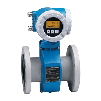
2 Identification Identification Device designation The “Promag 53” flow measuring system consists of the following components: • Promag 53 transmitter • Promag W, Promag P or Promag H sensor In the compact version, transmitter and sensor form a single mechanical unit; in the remote version they are installed separately. -
Page 8: Nameplate Of The Sensor
“Protection Measures for Electrical Equipment for Measurement, Control, Regulation and Laboratory Procedures”. The measuring system described in this Operating Instruction thus complies with the statutory requirements of the EC Directives. Endress+Hauser confirms successful testing of the device by affixing to it the CE mark. Endress+Hauser... -
Page 9: Device Certification Profibus-Dp/-Pa
2 Identification Device certification PROFIBUS-DP/-PA The Promag 53 flowmeter has passed all the test procedures implemented and has been certified and registered by the PNO (PROFIBUS User Organisation). The device thus meets all the requirements of the specifications listed below: •... - Page 10 2 Identification Promag 53 PROFIBUS-DP/-PA Endress+Hauser...
-
Page 11: Installation
Promag 53 PROFIBUS-DP/-PA 3 Installation Installation Incoming acceptance, transport and storage 3.1.1 Incoming acceptance • Check the packaging and the contents for damage. • Check the shipment, make sure nothing is missing and that the scope of supply matches your order. -
Page 12: Storage
3 Installation Promag 53 PROFIBUS-DP/-PA Transporting flanged devices (DN ≥ 350): Use only the metal eyes on the flanges for transporting the device, lifting it and position- ing the sensor in the piping. Caution: Do not attempt to lift the sensor with the tines of a fork-lift truck beneath the metal casing. -
Page 13: Installation Conditions
Promag 53 PROFIBUS-DP/-PA 3 Installation Installation conditions 3.2.1 Dimensions Dimensions and the fitting lengths of the transmitter and sensor are on Page 145 ff. 3.2.2 Mounting location Correct measuring is possible only if the pipe is full. Avoid the following locations: •... - Page 14 3 Installation Promag 53 PROFIBUS-DP/-PA Partially filled pipes Partially filled pipes with gradients necessitate a drain-type configuration. The Empty Pipe Detection function (see Page 106) offers additional protection by detecting empty or partially filled pipes. Caution: Risk of solids accumulating. Do not install the sensor at the lowest point in the drain. It is advisable to install a cleaning valve.
-
Page 15: Orientation
Promag 53 PROFIBUS-DP/-PA 3 Installation 3.2.3 Orientation An optimum orientation position helps avoid gas and air accumulations and deposits in the measuring tube. Promag, nevertheless, supplies a range of functions and accesso- ries for correct measuring of problematic fluids: • Electrode Cleaning Circuit (ECC) for applications with accretive fluids, e.g. electrically conductive deposits →... -
Page 16: Inlet And Outlet Runs
3 Installation Promag 53 PROFIBUS-DP/-PA 3.2.4 Inlet and outlet runs If possible, install the sensor well clear of fittings such as valves, T-pieces, elbows, etc. Compliance with the following requirements for the inlet and outlet runs is necessary in order to ensure measuring accuracy: •... -
Page 17: Foundations, Supports
Promag 53 PROFIBUS-DP/-PA 3 Installation 3.2.6 Foundations, supports If the nominal diameter is DN ≥ 350, mount the transmitter on a foundation of adequate load-bearing strength. Caution: Risk of damage. Do not support the weight of the sensor on the metal casing: the casing would buckle and damage the internal magnetic coils. -
Page 18: Adapters
3 Installation Promag 53 PROFIBUS-DP/-PA 3.2.7 Adapters Suitable adapters to (E) DIN EN 545 (double-flange reducers) can be used to install the sensor in larger-diameter pipes. The resultant increase in the rate of flow improves measuring accuracy with very slow-moving fluids. - Page 19 Promag 53 PROFIBUS-DP/-PA 3 Installation Promag W Flow rate characteristic values - Promag W (SI units) Nominal Recommended Factory setting diameter flow rate min./max. full scale value Full scale value Low flow cutoff [mm] [inch] (v ~ 0.3 or 10 m/s) (v ~ 2.5 m/s)
- Page 20 3 Installation Promag 53 PROFIBUS-DP/-PA Flow rate characteristic values - Promag W (US units) Nominal diameter Recommended Factory setting flow rate min./max. full scale value Full scale value Low flow cutoff [inch] [mm] (v ~ 0.3 or 10 m/s) (v ~ 2.5 m/s) (v ~ 0.04 m/s)
- Page 21 Promag 53 PROFIBUS-DP/-PA 3 Installation Promag P Flow rate characteristic values - Promag P (SI units) Nominal Recommended Factory setting diameter flow rate min./max. full scale value Full scale value Low flow cutoff [mm] [inch] (v ~ 0.3 or 10 m/s) (v ~ 2.5 m/s)
- Page 22 3 Installation Promag 53 PROFIBUS-DP/-PA Flow rate characteristic values - Promag P (US units) Nominal diameter Recommended Factory setting flow rate min./max. full scale value Full scale value Low flow cutoff [inch] [mm] (v ~ 0.3 or ~ 10 m/s) (v ~ 2.5 m/s)
- Page 23 Promag 53 PROFIBUS-DP/-PA 3 Installation Flow rate characteristic values - Promag H (US units) Nominal diameter Recommended Factory settings flow rate min./max. full scale value Full scale value Low flow cutoff [inch] [mm] (v ~ 0.3 or 10 m/s) (v ~ 2.5 m/s) (v ~ 0.04 m/s)
-
Page 24: Length Of Connecting Cable
3 Installation Promag 53 PROFIBUS-DP/-PA 3.2.9 Length of connecting cable In order to ensure measuring accuracy, comply with the following instructions when installing the remote version: • Secure the cable run or route the cable in a conduit. Movement of the cable can falsify the measuring signal, particularly if the fluid conductivity is low. -
Page 25: Installation
Promag 53 PROFIBUS-DP/-PA 3 Installation Installation 3.3.1 Installing the Promag W sensor Note: Bolts, nuts, seals, etc. are not included in the scope of supply and must be supplied by the customer. The sensor is designed for installation between the two piping flanges. Always tighten all threaded fasteners to the specified torques →... - Page 26 3 Installation Promag 53 PROFIBUS-DP/-PA Assembly with ground disks (DN 15...300) Depending on the application, e.g. with lined or ungrounded pipes (see Page 58 ff.), it may be necessary to mount ground disks between the sensor and the pipe flange for...
- Page 27 Promag 53 PROFIBUS-DP/-PA 3 Installation Torques of threaded fasteners (Promag W) Note the following points: • The tightening torques listed below are for lubricated threads only. • Always tighten threaded fasteners uniformly and in diagonally opposite sequence. • Overtightening the fasteners will deform the sealing faces or damage the seals.
- Page 28 3 Installation Promag 53 PROFIBUS-DP/-PA Promag W Threaded Max. tightening torque [Nm] Nominal diameter Pressure rating fasteners [mm] [bar] Hard rubber Polyurethane PN 10 20 x M 24 PN 16 20 x M 30 PN 25 20 x M 33...
- Page 29 Promag 53 PROFIBUS-DP/-PA 3 Installation Promag W AWWA Threaded Max. tightening torque [Nm] Nominal diameter Pressure rating fasteners [mm] [inch] Hard rubber Polyurethane 28" Class D 28 x 1 1/4" 30" Class D 28 x 1 1/4 32" Class D 28 x 1 1/2"...
- Page 30 3 Installation Promag 53 PROFIBUS-DP/-PA Promag W Threaded Max. tightening torque [Nm] Nominal diameter Pressure rating fasteners [mm] Hard rubber Polyurethane − 4 x M 16 − 4 x M 16 − 4 x M 16 − 4 x M 16 −...
-
Page 31: Installing The Promag P Sensor
Promag 53 PROFIBUS-DP/-PA 3 Installation 3.3.2 Installing the Promag P sensor Caution: • The protective covers mounted on the two sensor flanges guard the Teflon (PTFE) lin- ing, which is turned over the flanges. Consequently, do not remove these covers until immediately before the sensor is installed in the pipe. - Page 32 3 Installation Promag 53 PROFIBUS-DP/-PA Assembly with ground disks (DN 15...300) Depending on the application, e.g. with lined or ungrounded pipes (see Page 58 ff.), it may be necessary to mount ground disks between the sensor and the pipe flange for...
- Page 33 Promag 53 PROFIBUS-DP/-PA 3 Installation Installing the high-temperature version (with PFA/PTFE lining) The high-temperature version has a housing support for the thermal separation of sen- sor and transmitter. The high-temperature version is always used for applications in which high ambient temperatures are encountered in conjunction with high fluid tempe- ratures.
- Page 34 3 Installation Promag 53 PROFIBUS-DP/-PA Tightening torques for threaded fasteners (Promag P) Note the following points: • The tightening torques listed below are for lubricated threads only. • Always tighten threaded fasteners uniformly and in diagonally opposite sequence. • Overtightening the fasteners will deform the sealing faces or damage the seals.
- Page 35 Promag 53 PROFIBUS-DP/-PA 3 Installation Promag P Threaded Max. tightening torque [Nm] Nominal diameter Pressure rating fasteners [mm] [bar] PTFE − PN 25 20 x M 33 − PN 10 20 x M 27 − PN 16 20 x M 33 −...
- Page 36 3 Installation Promag 53 PROFIBUS-DP/-PA Promag P Threaded Max. tightening torque [Nm] Nominal diameter Pressure rating fasteners [mm] PTFE − 8 x M 16 − 8 x M 16 − 8 x M 20 − 8 x M 16 −...
-
Page 37: Installing The Promag H Sensor
Promag 53 PROFIBUS-DP/-PA 3 Installation 3.3.3 Installing the Promag H sensor The Promag H is supplied to order, with or without pre-installed process connections. Pre-installed process connections are secured to the sensor with hex-head threaded fasteners. Caution: • If you intend to use your own process connections, make up the process adapters as specified on Page 160 ff.. - Page 38 3 Installation Promag 53 PROFIBUS-DP/-PA Usage and assembly of ground rings (DN 2...25) In case the process connections are made of plastic (e.g. flanges or adhesive fittings), the potential between the sensor and the fluid must be equalised using additional ground rings.
- Page 39 Promag 53 PROFIBUS-DP/-PA 3 Installation Welding the sensor into the piping (weld nipple) Caution: Risk of destroying the measuring electronics. Make sure that the welding machine is not grounded via the sensor or the transmitter. Tack-weld the Promag H sensor into the pipe. A suitable welding jig can be ordered separately from E+H as an accessory (see Page 111).
-
Page 40: Turning The Transmitter Housing
3 Installation Promag 53 PROFIBUS-DP/-PA 3.3.4 Turning the transmitter housing Turning the aluminum field housing Warning: The turning mechanism in devices with EEx d/de or FM/CSA Cl. I Div. 1 classification is not the same as that described here. The procedure for turning these housings is described in the Ex-specific documentation. -
Page 41: Installing The Wall-Mount Transmitter
Promag 53 PROFIBUS-DP/-PA 3 Installation 3.3.5 Installing the wall-mount transmitter housing There are various ways of installing the wall-mount transmitter housing: • Mounted directly on the wall (without mounting kit) • Installation in control panel (with separate mounting kit, accessories → Page 111) •... - Page 42 3 Installation Promag 53 PROFIBUS-DP/-PA Panel installation Prepare the opening in the panel. Slide the housing into the opening in the panel from the front. Screw the fasteners onto the wall-mount housing. Place the threaded rods in the fasteners and screw them down until the housing is seated tightly against the panel.
-
Page 43: Turning The Local Display
Promag 53 PROFIBUS-DP/-PA 3 Installation 3.3.6 Turning the local display Remove the cover of the electronics compartment. Press the side latches on the display module and remove it from the electronics compartment cover plate. Rotate the display to the desired position (max. 4 x 45° in each direction), and place it back into the electronics compartment cover plate. -
Page 44: Installation Check
3 Installation Promag 53 PROFIBUS-DP/-PA Installation check Perform the following checks after installing the measuring device in the pipe: Device condition and specifications Notes − Is the device damaged (visual inspection)? Does the device correspond to specifications at the measuring point, see Page 131 ff. -
Page 45: Wiring
Promag 53 PROFIBUS-DP/-PA 4 Wiring Wiring Warning: • When connecting Ex-certified devices, see the notes and diagrams in the Ex-specific supplement to this Operating Instruction. Please do not hesitate to contact your E+H representative if you have any questions. • If you use remote versions, connect each sensor only to the transmitter having the same serial number. - Page 46 4 Wiring Promag 53 PROFIBUS-DP/-PA Stubs (PROFIBUS -DP) Note the following points: • Total combined length of all stubs < 6.6 m (at a max. of 1.5 MBit/s) • At transmission rates > 1.5 MBit/s, stubs should not be used.
- Page 47 Promag 53 PROFIBUS-DP/-PA 4 Wiring Setting the terminators Since mismatches in the impedance result in signal reflections on the line and can thus lead to communication errors, it is important to terminate the lines properly. Warning: Risk of electric shock. Exposed components carry dangerous voltages. Make sure that the power supply is switched off before you remove the cover of the electronics com- partment.
-
Page 48: Profibus-Pa: Cable Specifications
4 Wiring Promag 53 PROFIBUS-DP/-PA 4.1.2 PROFIBUS-PA: Cable specifications Cable type Twin-core cable is required for connecting the device to the fieldbus. By analogy with IEC 61158-2 protocol four different cable types (A, B, C, D) can be used with PROFIBUS protocol, only two of which (cable types A and B) are shielded. - Page 49 Promag 53 PROFIBUS-DP/-PA 4 Wiring Maximum overall cable length The maximum network expansion depends on the type of ignition protection and the cable specifications. The overall cable length is made up of the length of the main cable and the length of all spurs (>1 m). Note the following points: •...
-
Page 50: Connecting The Remote Version
4 Wiring Promag 53 PROFIBUS-DP/-PA Connecting the remote version 4.2.1 Connecting Promag W / P / H Warning: • Risk of electric shock. Switch off the power supply before opening the device. Do not install or wire the device while it is connected to the power supply. Failure to comply with this precaution can result in irreparable damage to the electronics. - Page 51 Promag 53 PROFIBUS-DP/-PA 4 Wiring Electrode circuit Pipe Meas. signal Coil circuit S1 E1 E2 S2 GND E S n.c. n.c. n.c. E1 E2 GND E Fig. 30: Connecting the Promag W/P remote version a = cover of the connection compartment, b = cover of the sensor connection housing, c = signal cable, d = coil current cable, n.c.
-
Page 52: Cable Specifications
4 Wiring Promag 53 PROFIBUS-DP/-PA 4.2.2 Cable specifications Coil cable • 2 x 0.75 mm PVC cable with common, braided copper shield (Ø approx. 7 mm) • Conductor resistance: ≤ 37 Ω /km • Capacitance: core/core, shield grounded: ≤ 120 pF/m •... -
Page 53: Connecting The Measuring Unit
Feed the power-supply cable (a) and PROFIBUS cable (b) through the appropriate cable entries. Note: The Promag 53 can also be supplied with the option of a ready-mounted fieldbus connector. More information on this can be found on Page 56. Connecting the cables: –... - Page 54 4 Wiring Promag 53 PROFIBUS-DP/-PA DP(A) / PA(-) DP(B) / PA(+) (+5 V) (DGND) N (L-) L1 (L+) Fig. 33: Connecting the transmitter (field housing), conductor cross-section: max. 2.5 mm A = Aluminium field housing B = Stainless steel housing Cable for power supply: 85...260 V AC, 20...55 V AC, 16...62 V DC...
-
Page 55: Terminal Assignment
Promag 53 PROFIBUS-DP/-PA 4 Wiring (DGND) N (L–) (+5 V) L1 (L+) DP (B) / PA (+) DP (A) / PA (–) 20 21 22 23 24 25 26 27 Fig. 34: Connecting the transmitter (wall-mount housing), conductor cross-section: max. 2.5 mm Cable for power supply: 85...260 V AC, 20...55 V AC, 16...62 V DC... -
Page 56: Fieldbus Connector
• Existing cable infrastructures can be used and expanded instantly, e.g. when con- structing new star distributors using 4-channel or 8-channel junction boxes. The Promag 53 can therefore be supplied with a ready-mounted fieldbus connector. Fieldbus connectors for retrofitting can be ordered from E+H as a spare part (see Page 111). - Page 57 Promag 53 PROFIBUS-DP/-PA 4 Wiring Technical data (fieldbus connector): Conductor size 0.75 mm Connector thread PG 13.5 Degree of protection IP 67 in accordance with DIN 40 050 IEC 529 Contact surface CuZnAu Housing material Cu Zn, surface Ni Flammability...
-
Page 58: Potential Equalisation
4 Wiring Promag 53 PROFIBUS-DP/-PA Potential equalisation 4.4.1 Standard case Proper measurement is only ensured when the fluid and sensor are at the same electri- cal potential. The majority of Promag sensors have, as part of their standard configura- tion, a built-in reference electrode, which ensures the required potential equalisation. As a rule, this is sufficient to eliminate the need for ground disks or other measures. -
Page 59: Special Cases
Promag 53 PROFIBUS-DP/-PA 4 Wiring 4.4.2 Special cases Equalising currents in metallic, ungrounded pipes To prevent disturbances to the measurement, we recommend that both sensor flanges be connected with a grounding cable to the adjacent pipe flange and to ground. Con- nect the transmitter or sensor connection housing, as applicable, to ground potential by means of the ground terminal provided for the purpose (Fig. - Page 60 4 Wiring Promag 53 PROFIBUS-DP/-PA Plastic pipes or pipes lined with insulating material Normally the potential equalisation is accomplished via the reference electrodes in the measuring tube. However, it is still possible that in some cases due to a plant's ground- ing design that a large equalisation current will flow over the reference electrodes.
-
Page 61: Degree Of Protection
Caution: Do not loosen the threaded fasteners of the Promag sensor housing, as otherwise the degree of protection guaranteed by Endress+Hauser no longer applies. Note: The Promag W and Promag P sensors can be supplied with IP 68 rating (permanent immersion in water to a depth of 3 meters). -
Page 62: Electrical Connection Check
4 Wiring Promag 53 PROFIBUS-DP/-PA Electrical connection check Perform the following checks after completing electrical installation of the measuring device: Device condition and specifications Notes − Are cables or the device damaged (visual inspection)? Electrical connection of meter Notes Does the supply voltage match the specifications on the nameplate? 85...260 V AC (45...65 Hz) -
Page 63: Operation
• Switch the hardware write protection on or off Fig. 41: Options for operating the Promag 53 PROFIBUS-DP/-PA Configuration / operation programs for operating the device via the PROFIBUS-DP/-PA Jumpers or miniature switches for hardware settings (write protection, device address) -
Page 64: Operation Via The Local Display
5 Operation Promag 53 PROFIBUS-DP/-PA Operation via the local display 5.2.1 Display and operating elements The local display enables you to read all important parameters directly at the measuring point and configure the device using the function matrix. The display consists of four lines; this is where measured values and/or status variables (direction of flow, empty pipe, bar graph, etc.) are displayed. - Page 65 Promag 53 PROFIBUS-DP/-PA 5 Operation Display The display area consists of three lines in all; this is where measured values are dis- played, and/or status variables (direction of flow, partially filled pipe, bargraph, etc.). You can change the assignment of display lines to variables at will in order to customize the display to suit your needs and preferences ( →...
- Page 66 5 Operation Promag 53 PROFIBUS-DP/-PA Other icons Measuring mode = PULSATING FLOW Counting mode, totalizer = BALANCE (forwards and reverse flow) Measuring mode = SYMMETRY (bidirectional) Counting mode, totalizer = forwards Measuring mode = STANDARD Counting mode, totalizer = reverse...
-
Page 67: Brief Description Of The Function Matrix
Promag 53 PROFIBUS-DP/-PA 5 Operation 5.2.2 Brief description of the function matrix Note: • See the general notes on Page 68. • Function descriptions → see the “Description of Device Functions” manual HOME position → → Enter the function matrix Select a block (e.g. - Page 68 There is no need to change these parameters under normal circumstances and conse- quently, they are protected by a special code known only to the E+H service organisa- tion. Please contact Endress+Hauser if you have any questions. Endress+Hauser...
-
Page 69: Error Messages
Promag 53 PROFIBUS-DP/-PA 5 Operation Disabling the programming mode Programming mode is disabled if you do not press a key within 60 seconds following automatic return to the HOME position. You can also disable programming in the “ACCESS CODE” function by entering any number (other than the customer's code). -
Page 70: Communications: Profibus-Dp/-Pa
5 Operation Promag 53 PROFIBUS-DP/-PA Confirming error messages For the sake of plant and process safety, the measuring device can be configured in such a way that fault messages ( ) always have to be rectified and acknowledged locally by pressing . -
Page 71: Profibus-Dp System Architecture
Filling function In contrast to the functionality of a Promag 53 that does not support the PROFIBUS, the internal filling function is not integrated in the PROFIBUS-DP devices, since the device does not have any relay functions. -
Page 72: Profibus-Pa System Architecture
4 = PROFIBUS-DP RS 485 line (max. 12 MBit/s), 5 = PROFIBUS-PA IEC 61158-2 (max. 31.25 kbit/s) General information The Promag 53 can be equipped with a PROFIBUS-PA interface in accordance with the fieldbus standard PROFIBUS-DP (EN 50170 Volume 2). - Page 73 The master can be an automation control system, a PLC or a PC with a PROFIBUS-DP communications adapter card. Note: During the project planning, please remember that the Promag 53 consumes 11 mA. Caution: To prevent severe device failures (e.g. short-circuits) from having effect on the PROFIBUS-PA segment, the IEC 61158-2 interface is equipped with a fuse.
-
Page 74: Acyclic Data Exchange
• Two Classe 2 masters are permitted with a Promag. This means that two Class 2 mas- ters can access the Promag 53 at the same time. However, you must make certain that they do not both attempt to write the same data, since otherwise the data consistency cannot be guaranteed. -
Page 75: Operation With The Profibus Configuration Programs
• An exact description of the data types can be found in the slot/index lists in the “Description of Device Functions” manual. As an aid in programming with Commuwin II, all of the Promag 53's device functions are clearly arranged in a matrix. - Page 76 5 Operation Promag 53 PROFIBUS-DP/-PA Device matrix Endress+Hauser...
- Page 77 Promag 53 PROFIBUS-DP/-PA 5 Operation Display functions (partial matrix) Endress+Hauser...
- Page 78 5 Operation Promag 53 PROFIBUS-DP/-PA Diagnosis/Alarm/Simulation/Version Info/Service&Analysis (partial matrix) Endress+Hauser...
- Page 79 Promag 53 PROFIBUS-DP/-PA 5 Operation Physical Block (operation via profile) Endress+Hauser...
- Page 80 5 Operation Promag 53 PROFIBUS-DP/-PA Transducer Block flow (operation via profile) Endress+Hauser...
- Page 81 Promag 53 PROFIBUS-DP/-PA 5 Operation Analog Input Block (operation via profile) Endress+Hauser...
- Page 82 5 Operation Promag 53 PROFIBUS-DP/-PA Totalizer Block (operation via profile) Endress+Hauser...
-
Page 83: Hardware Configuration
Promag 53 PROFIBUS-DP/-PA 5 Operation Hardware configuration 5.5.1 Configuration of write protection A jumper on the I/O board provides the means of activating or deactivating hardware write protection. Warning: Risk of electric shock. Exposed components carry dangerous voltages. Make sure that the power supply is switched off before you remove the cover of the electronics com- partment. -
Page 84: Configuration Of The Device Address
5 Operation Promag 53 PROFIBUS-DP/-PA 5.5.2 Configuration of the device address Note the following points: • In the case of a PROFIBUS-DP/-PA flowmeter, it will always be necessary to configure the address. Valid flowmeter addresses lie within the range 0…125. Each address can only be used once in a PROFIBUS-DP/-PA network. -
Page 85: Commissioning
Promag 53 PROFIBUS-DP/-PA 6 Commissioning Commissioning Function check Make sure that all final checks have been completed before you start up your measuring point: • Checklist for “Installation check” → Page 44 • Checklist for “Electric connection check” → Page 62 Note: •... -
Page 86: Commissioning The Profibus-Dp/-Pa Interface Using The Local Display
FUNCTIONS) → PROFIBUS-DP/-PA (GBA) → OPERATION (614) → SET UNIT TO BUS (6141) has been activated. Configuration of the totalizers 1-3: Promag 53 disposes of 3 totalizers. The following description provides an example for totalizer 1. – Selection of the process variables with the parameter CHANNEL e.g. volume flow: BASIC FUNCTION (G) →... -
Page 87: Commissioning Using The Class 2 Master (Commuwin Ii)
Parametering the “Physical Block”: – Open the Physical Block. – Software and hardware write protection is disabled in Promag 53 so that you can access all the write parameters. Check this status with the parameters WRITE LOCKING (V3H0, software write protection) and HW WRITE PROTECT (V3H1, hardware write protection). - Page 88 6 Commissioning Promag 53 PROFIBUS-DP/-PA Parametering the “Totalizer Block”: Promag 53 comprises three Totalizer function blocks. These are selected using the profile blocks “Totalizer Block” in the connection clearance list. – Enter the required name for the Totalizer function block.
-
Page 89: Rescaling The Input Value
Promag 53 PROFIBUS-DP/-PA 6 Commissioning 6.3.1 Rescaling the input value In the Analog Input function block the input value or input range can be scaled in accordance with the automation requirements. Example: • The system unit in the Transducer Block is m •... -
Page 90: System Integration
This guarantees that the first measured variable agrees with the field equipment of other manufacturers. The second AI block can be freely selected as Promag 53 is capable of producing a calculated mass flow (see configura- tion example on Page 98 ff.). - Page 91 (PNO). The name of the PROFIBUS description file (GSD) is derived from this. At Endress+Hauser, this ID No. starts with the manufacturer ID 15xx. In order to ensure clarity, the GSD names (with the exception of type files) at Endress+Hauser are as...
- Page 92 This differenciation is the result of a specific implementation in the master systems. Contents of the download file from the internet and the CD-ROM: • All Endress+Hauser GSD files • Endress+Hauser type files • Endress+Hauser bitmap files • Useful information relating to the devices Working with GSD / type files The GSD files must be integrated into the automation control system.
-
Page 93: Cyclic Data Exchange
Promag 53 PROFIBUS-DP/-PA 6 Commissioning 6.4.1 Cyclic data exchange In the case of PROFIBUS-DP/-PA, the cyclic transmission of analog values to the auto- mation control system is effected in data blocks of 5 bytes. The measured value is por- trayed in the first 4 bytes in the form of flowing point numbers in accordance with IEEE 754 standard (see IEEE floating point number). - Page 94 • Totalizers 1-3 and the corresponding control parameters • Calculated mass flow (see “Description of Device Functions” manual) • Display value • Control blocks for manufacturer-specific functions The block model shows the input and output data which Promag 53 provides for data exchange. Local operation TOTALIZER...
- Page 95 Promag 53 PROFIBUS-DP/-PA 6 Commissioning Input data The following are examples of input data: volume flow, totalizers 1-3 and calculated mass flow. The current volume flow, totalizers 1-3 and calculated mass flow can be displayed on the basis of these measured variables. The calculated mass flow is derived from the vol- ume flow and a fixed density.
- Page 96 Control variables (output data) manufacturer-specific Promag 53 is capable of processing control variables during the cyclic data exchange e.g the switching on positive zero return. The following table shows the control variables (output data) that can be transferred to Promag 53.
- Page 97 Only activate the data blocks which are to be processed in the automation control sys- tem. This will improve the data throughput rate of a PROFIBUS-DP/-PA network. A blinking double-arrow symbol will appear on the display to show that Promag 53 is communicating with the automation control system.
- Page 98 The configuration of a PROFIBUS-DP system is normally effected in the following manner: The field device (Promag 53) which is to be configured is integrated into the con- figuration program of the automation control system via the PROFIBUS-DP network. The GSD file is used here. The configuration software can be used to configure measured variables “offline”.
-
Page 99: Configuration Examples With Simatic S7 Hw-Konfig
Slot 4 → AI mass flow Slot 5: Display value (DISPLAY_VALUE) Slot 6: Control block (CONTROL_BLOCK) manufacturer-specific This form of configuration activates all data blocks which are supported by Promag 53. The significance of SET_TOT and MODE_TOT is described on Page 97. Configuration data... - Page 100 6 Commissioning Promag 53 PROFIBUS-DP/-PA Example 2: Replacing measured variables with placeholders (EMPTY_MODULE) using the manu- facturer-specific GSD file: Slot 0: AI volume flow Slot 1: Totalizer 1 “without control variable” Slot 2: Placeholder (EMPTY_MODULE) Slot 3: Placeholder (EMPTY_MODULE) Slot 4: Placeholder (EMPTY_MODULE)
- Page 101 Promag 53 PROFIBUS-DP/-PA 6 Commissioning Example 3: Configuration of the measured variables without placeholders (EMPTY_MODULE) using the manufacturer-specific GSD file. Slot 0: AI volume flow Slot 1: Totalizer 1 + Control variable (SET_TOT) This form of configuration transfers the volume flow - totalizer 1 with control variable (SET_TOT).
- Page 102 The first AI block is always assigned to the volume flow. This guarantees that the first measured variable agrees with the field equipment of other manufacturers. The second AI block can be freely selected as Promag 53 is capable of producing a calculated mass flow.
- Page 103 Promag 53 PROFIBUS-DP/-PA 6 Commissioning Status code The status codes which are supported by the AI blocks (Analog Input), TOT (Totalizers 1...3) and display value are listed in the following table. The coding of the status corresponds to “PROFIBUS-PA Profile for Process Control Devices - General Requirements”...
-
Page 104: Cycle Times
The duration of the sampling intervals will depend on the type of sensor that is being used, the nominal diameter and the energy supply (50 Hz, 60 Hz, DC). The typical processing times of Promag 53 can be found in the following table: Sensor... - Page 105 Promag 53 PROFIBUS-DP/-PA 6 Commissioning 3rd step: PROFIBUS protocol chip The cyclic data telegram is transferred to the protocol chip and, following an inquiry from the master, is sent to the master in accordance with the data transfer rate. Endress+Hauser...
-
Page 106: Empty-Pipe/Full-Pipe Calibration
6 Commissioning Promag 53 PROFIBUS-DP/-PA Empty-pipe/full-pipe calibration Flow cannot be measured correctly unless the measuring tube is full. The Empty Pipe Detection function (EPD = Empty Pipe Detection) allows this status to be monitored con- tinuously. The EPD function cannot be activated until after empty/full pipe calibration has been performed. -
Page 107: Data Storage Device (Dat, F-Chip™)
Promag 53 PROFIBUS-DP/-PA 6 Commissioning Data storage device (DAT, F-Chip™) S-DAT™ (Sensor-DAT) The S-DAT™ is an exchangeable data storage chip in which all sensor relevant param- eters are stored, i.e., diameter, serial number, calibration factor, zero point. T-DAT™ (Transmitter-DAT) The T-DAT™ is an exchangeable data storage chip in which all transmitter parameters and settings are stored. - Page 108 6 Commissioning Promag 53 PROFIBUS-DP/-PA Endress+Hauser...
-
Page 109: Maintenance
Promag 53 PROFIBUS-DP/-PA 7 Maintenance Maintenance The Promag 53 flow measuring system requires no special maintenance. Exterior cleaning When cleaning the exterior of flowmeters, always use cleaning agents that do not attack the surface of the housing and the seals. - Page 110 7 Maintenance Promag 53 PROFIBUS-DP/-PA Endress+Hauser...
-
Page 111: Accessories
Promag 53 PROFIBUS-DP/-PA 8 Accessories Accessories Various accessories, which can be ordered separately from Endress+Hauser, are avail- able for the transmitter and the sensor. The E+H service organisation can provide detailed information on the order codes of your choice. Accessory... - Page 112 8 Accessories Promag 53 PROFIBUS-DP/-PA Accessory Description Ordering code DKA80 − * Applicator ™ Software for selecting and configuring flow- meters. Applicator™ can be downloaded from the Internet or ordered on CD-ROM for installa- tion on a local PC. Contact your E+H representative for more information.
-
Page 113: Trouble-Shooting
In the event of a serious fault, a flowmeter might have to be returned to the manufacturer for repair. The procedures on Page 6 must be carried out before you return a device to Endress+Hauser. Always enclose a duly completed “Safety regulation” form. You will find a preprinted form at the back of this manual. - Page 114 9 Trouble-shooting Promag 53 PROFIBUS-DP/-PA Faulty connection to control system No connection can be made between the control system and the device. Check the following points: Check the supply voltage → terminals 1/2 Supply voltage Transmitter Check device fuse → Page 127 Device fuse 85...260 V AC: 0,8 A slow-blow / 250 V...
-
Page 115: System And Process Error Messages
Error messages in the configuration program (Class 2 Master) → see Table In the Promag 53 system/process errors are recognised and reported in the Transducer Block and Analog Input Block. The following table contains a listing of the device status messages for the Analog Input blocks (PROFIBUS-Profile 3.0) and a description of the... - Page 116 9 Trouble-shooting Promag 53 PROFIBUS-DP/-PA Device status Device status Initial status Measured Cause/remedy message message Analog Input Block/ value Q / Diagnosis message (Display) Totalizer Block Substatus/ (Control system) alarm limit Amplifier EEPROM S MP SW-EEPROM device failure Cause: data inconsistent...
- Page 117 Promag 53 PROFIBUS-DP/-PA 9 Trouble-shooting Device status Device status Initial status Measured Cause/remedy message message Analog Input Block/ value Q / Diagnosis message (Display) Totalizer Block Substatus/ (Control system) alarm limit T-DAT failure S TRANSM. HW DAT device failure Cause:...
- Page 118 9 Trouble-shooting Promag 53 PROFIBUS-DP/-PA Device status Device status Initial status Measured Cause/remedy message message Analog Input Block/ value Q / Diagnosis message (Display) Totalizer Block Substatus/ (Control system) alarm limit Restore from T-DAT S SAVE T-DAT device failure Cause:...
- Page 119 Promag 53 PROFIBUS-DP/-PA 9 Trouble-shooting Device status Device status Initial status Measured Cause/remedy message message Analog Input Block/ value Q / Diagnosis message (Display) Totalizer Block Substatus/ (Control system) alarm limit EPD adjustment wrong P EPD FULL=EMPTY non specific UNCERTAIN...
- Page 120 9 Trouble-shooting Promag 53 PROFIBUS-DP/-PA Device status Device status Initial status Measured Cause/remedy message message Analog Input Block/ value Q / Diagnosis message (Display) Totalizer Block Substatus/ (Control system) alarm limit Simulation mass flow S SIM. MASS FLOW simulated value...
-
Page 121: Process Errors Without Messages
Returning devices to E+H The procedures on Page 6 must be carried out before you return a flow- meter requiring repair or calibration to Endress+Hauser. Always enclose a duly completed “Safety regulation” form with the device. You will find a preprinted “Safety regulation” form at the back of this manual. -
Page 122: Spare Parts
• Spare part • Additional parts, small items (fasteners, etc.) • Mounting instructions • Packaging Fig. 53: Spare parts for Promag 53 transmitter (field and wall-mount housings) Power supply board Amplifier board I/O board (Type PROFIBUS-DP/-PA) S-DAT™ (sensor data memory) T-DAT™... -
Page 123: Removing And Installing Printed Circuit Boards
– Disconnect the plug of the coil current cable (5.2) from the board. – Insert a thin pin into the hole (3) provided for the purpose and pull the board clear of its holder. Installation is the reverse of the removal procedure. Caution: Use only original Endress+Hauser parts. Endress+Hauser... - Page 124 9 Trouble-shooting Promag 53 PROFIBUS-DP/-PA Fig. 54: Field housing: removing and installing printed circuit boards Local display Latch Ribbon cable (display module) Screws of electronics compartment cover Aperture for installing/removing boards Power supply board Amplifier board Signal cable (sensor) Coil current cable (sensor) S-DAT™...
- Page 125 Extension of boards (6, 7, 8): Insert a thin pin into the hole (5) provided for the purpose and pull the board clear of its holder. Installation is the reverse of the removal procedure. Caution: Use only original Endress+Hauser parts. Endress+Hauser...
- Page 126 9 Trouble-shooting Promag 53 PROFIBUS-DP/-PA Fig. 55: Wall-mounted housing: removing and installing printed circuit boards Housing cover Electronics module Ribbon cable (display module) Screws of electronics compartment cover Aperture for installing/removing boards Power supply board Amplifier board Signal cable (sensor) Coil current cable (sensor) S-DAT™...
-
Page 127: Replacing The Device Fuse
– Power supply 85...260 V AC → 0.8 A slow-blow / 250 V; 5.2 x 20 mm – Ex-rated devices → see the Ex documentation. Assembly is the reverse of the disassembly procedure. Caution: Use only original Endress+Hauser parts. Fig. 56: Replacing the device fuse on the power supply board Protective cap... -
Page 128: Replacing Exchangeable Measuring Electrodes
9 Trouble-shooting Promag 53 PROFIBUS-DP/-PA Replacing exchangeable measuring electrodes The Promag W sensor (DN 350...2000) is available with exchangeable measuring elec- trodes as an option. This design permits the measuring electrodes to be replaced or cleaned under process conditions (see Page 129). - Page 129 Promag 53 PROFIBUS-DP/-PA 9 Trouble-shooting Removing the electrode Installing the electrode Loosen Allen screw (a) and remove the Insert new electrode (e) into retaining cylin- cover. der (g) from below. Make sure that the seals at the tip of the electrode are clean.
-
Page 130: Software History
9 Trouble-shooting Promag 53 PROFIBUS-DP/-PA Software history Software version / date Altering the software Documentation: Alterations / supplements − Amplifier: Original software. V 1.01.01 Compatible with: I/O board – FieldTool ™ Type PROFIBUS-DP/-PA: – Commuwin II (version 2.07.XX and V 1.00.00 higher) –... -
Page 131: Technical Data
Two versions are available: – Compact version – Remote version Transmitter • Promag 53 (Type PROFIBUS-DP/-PA) Sensor • Promag W (for water / waste water applications) DN 25...2000, hard rubber or polyurethane lining • Promag P (for chemical and process applications) DN 15...600, PFA or PTFE lining... - Page 132 10 Technical data Promag 53 PROFIBUS-DP/-PA Power supply Electrical connection see Page 45 ff. Potential equalisation see Page 58 ff. Cable entries Power supply and signal cables (inputs/outputs): – Cable entry M20 x 1.5 (8...12 mm) – Threads for cable entries PG 13.5 (5...15 mm), 1/2" NPT, G 1/2"...
- Page 133 Promag 53 PROFIBUS-DP/-PA 10 Technical data Operating conditions Installation Installation instructions Any orientation (vertical, horizontal) Restrictions and additional installation instructions → Page 13 ff. Inlet run: typically ≥ 5 x DN Inlet and outlet runs Outlet run: typically ≥ 2 x DN...
- Page 134 10 Technical data Promag 53 PROFIBUS-DP/-PA Process Medium temperature The permissible fluid temperature depends on the lining of the measuring range tube: Promag W 0...+80 °C in the case of hard rubber (DN 65...2000) –20...+70 °C in the case of polyurethane (DN 25...2000) Promag P –40...+130 °C in the case of PTFE (DN 15...600), restrictions →...
- Page 135 Promag 53 PROFIBUS-DP/-PA 10 Technical data Promag H Sensor: • DN 2...25: –20...+150 °C (+180 °C in prep.) • DN 40...100: –20...+150 °C Seal: • EPDM: –20...+130 °C • Silicone: –20...+150 °C • Viton: –20...+150 °C • Kalrez: –20...+150 °C...
- Page 136 10 Technical data Promag 53 PROFIBUS-DP/-PA Mechanical construction Design / dimensions see Page 145 ff. Weight see Page 143 ff. Materials Promag W Transmitter housing: • Compact housing: powder-coated die-cast aluminum or stainless steel field housing (1.4301 / 316L) • Wall-mounted housing: powder-coated die-cast aluminium Sensor housing: •...
- Page 137 Promag 53 PROFIBUS-DP/-PA 10 Technical data Promag H Transmitter housing: • Compact housing: powder-coated die-cast aluminum or stainless-steel field housing (1.4301 / 316L) • Wall-mounted housing: powder-coated die-cast aluminium Sensor housing: 1.4301 Wall assembly set: 1.4301 Measuring pipe: stainless steel 1.4301 or 1.4306 (304L) Flanges: •...
- Page 138 EC Directives. Endress+Hauser confirms successful testing of the device by affixing to it the CE mark. Certification The Promag 53 flowmeter has passed all the test procedures implemented PROFIBUS-DP/-PA and has been certified and registered by the PROFIBUS User Organisation.
- Page 139 • Technical Information Promag 50/53 W (TI 046D/06/en) • Technical Information Promag 50/53 P (TI 047D/06/en) • Technical Information Promag 50/53 H (TI 048D/06/en) • Description of Device Functions Promag 53 (BA054D/06/de) • Supplementary documentation on Ex-ratings: ATEX, FM, CSA, etc. Endress+Hauser...
-
Page 140: Measuring Tube Specifications
10 Technical data Promag 53 PROFIBUS-DP/-PA 10.2 Measuring tube specifications Promag W Pressure rating Inside diameter of measuring Nominal diameter tube ANSI ANSI AWWA Hard rubber Polyurethane [mm] [inch] [bar] [lbs] − − 1" PN 40 Cl 150 − −... - Page 141 Promag 53 PROFIBUS-DP/-PA 10 Technical data Promag P Pressure rating Inside diameter of measuring Nominal diameter tube ANSI ANSI with PFA with PTFE [mm] [inch] [bar] [lbs] [mm] [mm] − 1/2" PN 40 Cl 150 1" PN 40 Cl 150 −...
-
Page 142: Resistance To Partial Vacuum Of Measuring Tube Lining
10 Technical data Promag 53 PROFIBUS-DP/-PA 10.3 Resistance to partial vacuum of measuring tube lining Promag W Measuring Resistance to partial vacuum of measuring tube lining Limit values for abs. pressure [mbar] at various fluid temperatures Nominal diameter tube lining... -
Page 143: Weight Details
Promag 53 PROFIBUS-DP/-PA 10 Technical data 10.4 Weight details Weight details Promag W in kg Nominal Compact version Remote version (without cable) diameter Wall [mm] [inch] ANSI / AWWA Sensor housing 1" 1 1/4" – – 1 1/2" 2" 10.6 2 1/2"... - Page 144 10 Technical data Promag 53 PROFIBUS-DP/-PA Weight details Promag P in kg Nominal Compact version Remote version (without cable) diameter Wall [mm] [inch] ANSI / AWWA Sensor housing 1/2" 1" 1 1/4" – – 1 1/2" 2" 10.6 10.6 2 1/2"...
-
Page 145: Dimensions Of Wall-Mount Housing
Promag 53 PROFIBUS-DP/-PA 10 Technical data 10.5 Dimensions of wall-mount housing Dimensions of wall-mounted housing (control panel mounting and pipe mounting → Page 42) Fig. 58: Endress+Hauser... -
Page 146: Dimensions Promag 53 W
10 Technical data Promag 53 PROFIBUS-DP/-PA 10.6 Dimensions Promag 53 W Promag W / DN ≤ 300 (compact version) Dimensions Promag W / DN ≤ 300 (compact version) Fig. 59: ANSI [mm] [inch] [mm] [mm] [mm] [mm] [mm] [mm] 1"... - Page 147 Promag 53 PROFIBUS-DP/-PA 10 Technical data Promag W / DN ≤ 300 (remote version) Dimensions Promag W / DN ≤ 300 (remote version) Fig. 60: Dimensions of wall-mount housing → see Page 145 ANSI [mm] [inch] [mm] [mm] [mm] [mm]...
- Page 148 10 Technical data Promag 53 PROFIBUS-DP/-PA Promag W / DN ≥ 350 (compact version) Dimensions Promag W / DN ≥ 350 (compact version) Fig. 61: ANSI [mm] [inch] [mm] [mm] [mm] [mm] [mm] [mm] 14" 738.5 456.5 282.0 16" 790.5 482.5...
- Page 149 Promag 53 PROFIBUS-DP/-PA 10 Technical data Promag W / DN ≥ 350 (remote version) Dimensions Promag W / DN ≥ 350 (remote version) Fig. 62: Dimensions of wall-mount housing → see Page 145 ANSI [mm] [inch] [mm] [mm] [mm] [mm]...
-
Page 150: Dimensions Promag 53 P
10 Technical data Promag 53 PROFIBUS-DP/-PA 10.7 Dimensions Promag 53 P Promag P / DN ≤ 300 (compact version) Dimensions Promag P / DN ≤ 300 (compact version) Fig. 63: ANSI [mm] [inch] [mm] [mm] [mm] [mm] [mm] [mm] 1/2"... - Page 151 Promag 53 PROFIBUS-DP/-PA 10 Technical data Promag P / DN ≤ 300 (remote version) Dimensions Promag P / DN ≤ 300 (remote version) Fig. 64: Dimensions of wall-mount housing → see Page 145 ANSI [mm] [inch] [mm] [mm] [mm] [mm]...
- Page 152 10 Technical data Promag 53 PROFIBUS-DP/-PA Promag P / DN ≤ 300 / high-temperature version (compact version) Abb. 65: Dimensions of high-temperature version (Promag P, DN ≤ 300, compact) Dimensions A1, B1 = A, B of standard version plus 110 mm Promag P / DN ≤...
- Page 153 Promag 53 PROFIBUS-DP/-PA 10 Technical data Promag P / DN ≥ 350 (compact version) Dimensions Promag P / DN ≥ 350 (compact version) Fig. 67: ANSI [mm] [inch] [mm] [mm] [mm] [mm] [mm] [mm] 14" 738.5 456.5 282.0 16" 790.5 482.5...
- Page 154 10 Technical data Promag 53 PROFIBUS-DP/-PA Promag P / DN ≥ 350 (remote version) Dimensions Promag P / DN ≥ 350 (remote version) Fig. 68: Dimensions of wall-mount housing → see Page 145 ANSI [mm] [inch] [mm] [mm] [mm] [mm]...
-
Page 155: Dimensions Of Ground Disks (Promag W, P)
Promag 53 PROFIBUS-DP/-PA 10 Technical data 10.8 Dimensions of ground disks (Promag W, P) Ø B Ø A Ø D Fig. 69: Dimensions of ground disks DN 25...300 (Promag W, P) ANSI [mm] [inch] [mm] [mm] [mm] [mm] 1" 77.5 87.5... -
Page 156: Dimensions Promag 53 H
10 Technical data Promag 53 PROFIBUS-DP/-PA 10.9 Dimensions Promag 53 H Promag H / DN 2...25 (compact version) Fig. 70: Dimensions Promag H / DN 2...25 (compact version, aluminum field housing) Es c Fig. 71: Dimensions Promag H / DN 2...25 (compact version, stainless-steel field housing) - Page 157 Promag 53 PROFIBUS-DP/-PA 10 Technical data Promag H / DN 2...25 (remote version) Fig. 72: Dimensions Promag H / DN 2...25 (remote version) PN * ANSI [mm] [inch] [bar] [mm] [mm] [mm] [mm] [mm] [mm] [mm] − 16/40 2.25 M 6x4 −...
- Page 158 10 Technical data Promag 53 PROFIBUS-DP/-PA Promag H / DN 40...100 (compact version) Fig. 74: Dimensions Promag H / DN 40...100 (compact version, aluminum field housing) Es c Fig. 75: Dimensions Promag H / DN 40...100 (compact version, stainless-steel field housing)
- Page 159 Promag 53 PROFIBUS-DP/-PA 10 Technical data Promag H / DN 40...100 (remote version) Fig. 76: Dimensions Promag H / DN 40...100 (remote version) Dimensions of wall-mount housing → see Page 145 ANSI [mm] [inch] [bar] [mm] [mm] [mm] [mm] [mm]...
-
Page 160: Process Connections Promag H (Dn 2
10 Technical data Promag 53 PROFIBUS-DP/-PA 10.10 Process connections Promag H (DN 2...25) Front view of sensor Promag H / DN 2...25 (without process connections) DN 2...15 DN 25 ±0.1 ±0.1 ±0.1 ±0.1 Fig. 77: Dimensions front view of sensor DN 2...25... - Page 161 Promag 53 PROFIBUS-DP/-PA 10 Technical data Process connections with O-ring seals (DN 2...25) Weld nipples ISO 2463 Sensor Pipe H x B 1.4404 / 316L DN [mm] Tube [mm] [mm] [mm] [mm] 5*H**-B*********** 2...8 13.5 x 1.6 10.3 13.5 20.3 60 x 42 21.3 x 1.6...
- Page 162 10 Technical data Promag 53 PROFIBUS-DP/-PA Flange JIS B2238 / 20K Sensor Pipe H x B 1.4404 / 316L DN [mm] Flange [mm] [mm] [mm] [mm] [mm] [mm] 5*H**-F*********** 2...8 ND 10 60 x 42 ND 15 60 x 42...
- Page 163 Promag 53 PROFIBUS-DP/-PA 10 Technical data External pipe thread ISO 228 / Sensor Pipe H x B DIN 2999, 1.4404 / 316L Internal thread 5*H**-K*********** DN [mm] [inch] [mm] [inch] [mm] [mm] [mm] 2...8 R 3/8" 3/8" 10.1 60 x 42 R 1/2"...
- Page 164 10 Technical data Promag 53 PROFIBUS-DP/-PA Process connections with aseptic gasket seal (DN 2...25 ) Weld nipple DIN 11850 Sensor Pipe H x B 1.4404 / 316L DN [mm] Tube [mm] [mm] [mm] [mm] 5*H**-U*********** 2...8 14 x 2 23.3...
- Page 165 Promag 53 PROFIBUS-DP/-PA 10 Technical data Tri-clamp for ODT Sensor Pipe H x B 1.4404 / 316L DN [mm] Tri-Clamp [mm] [mm] [mm] [mm] 5*H**-1*********** 2...8 Tube 12.7 x 1.65 25.0 28.5 60 x 42 (ODT 1/2") Tube 19.1 x 1.65 15.8...
- Page 166 10 Technical data Promag 53 PROFIBUS-DP/-PA Coupling SMS 1145 Sensor Pipe H x B 1.4404 / 316L DN [mm] Coupling [inch] [mm] [mm] [mm] [mm] 5*H**-5*********** 1" (25 ANSI) 1" 22.1 Rd 40 x 1/6" 30.8 70 x 52 – Fitting length = (2 x L) + 86 mm –...
- Page 167 Promag 53 PROFIBUS-DP/-PA 10 Technical data Process connections orderable only as accessories (with gasket seal) Tri-clamp for ODT Sensor Pipe H x B 1.4404 / 316L DN [mm] Tri-Clamp [mm] [mm] [mm] [mm] DKH**-HF*** Tube 25.4 x 1.5 22.1 50.4 28.5...
-
Page 168: Process Connections Of Promag H
10 Technical data Promag 53 PROFIBUS-DP/-PA 10.11 Process connections of Promag H (DN 40...100) Front view of sensor Promag H / DN 40...100 (without process connection) Fig. 78: Dimensions front view of sensor DN 40...100 [mm] [mm] [mm] [mm] [mm]... - Page 169 Promag 53 PROFIBUS-DP/-PA 10 Technical data Process connections with gasket seal (DN 40...100) Weld nipples DIN 11850 1.4404 / 316L [mm] [mm] [mm] [mm] [mm] [mm] [mm] 5*H**-U*********** 38.0 71.0 50.0 83.5 66.0 100.0 81.0 121.0 100.0 141.5 – Fitting length = (2 x L) + 140 mm (DN 40...65) / + 200 mm (DN 80...100) –...
- Page 170 10 Technical data Promag 53 PROFIBUS-DP/-PA Tri-clamp for ODT 1.4404 / 316L [mm] [inch] [mm] [mm] [mm] [mm] [mm] 5*H**-1*********** 1 1/2" 34.8 50.4 68.6 71.0 2" 47.5 63.9 68.6 83.5 − 60.2 77.4 68.6 100.0 3" 72.9 90.9 68.6 121.0...
- Page 171 Promag 53 PROFIBUS-DP/-PA 10 Technical data Coupling SMS 1145 1.4404 / 316L [mm] [mm] [mm] [mm] [mm] [mm] 5*H**-5*********** 35.5 Rd 60 x 1/6" 71.0 48.5 Rd 70 x 1/6" 83.5 60.5 Rd 85 x 1/6" 100.0 72.0 Rd 98 x 1/6"...
- Page 172 10 Technical data Promag 53 PROFIBUS-DP/-PA Endress+Hauser...
-
Page 173: Index
Promag 53 H (DN 40...100) ....158 Promag 53 P (DN ≤ 300) ....150 Block model . - Page 174 Index Promag 53 PROFIBUS-DP/-PA device fuse ......127 adapters ....... 18 measuring electrodes .
- Page 175 Promag 53 PROFIBUS-DP/-PA Index Commuwin II (operating software) ... 75 Promag P ....... 31 display and operating elements .
- Page 176 Index Promag 53 PROFIBUS-DP/-PA Endress+Hauser...