
Related Manuals for GE NX-4-EUR


Summary of Contents for GE NX-4-EUR
-
Page 1: Installation Manual
Security NetworX Series NX-4-EUR Control Panel Installation manual imagination at work... - Page 2 NX-4-EUR Installation manual Page 2 02/07/06...
-
Page 3: Table Of Contents
FOR PARTITION ......................................... 45 NTRY XIT TIMERS ..............................46 ONE CONFIGURATIONS AND PARTITION SELECTION .......................................... 49 ENERAL OPTIONS ....................................... 53 ROGRAMMING THE OUTPUTS ......................... 55 ETUP FOR AUTO TEST AUTO ARM AND OPENING CLOSING TIMES NX-4-EUR Installation manual Page 3 02/07/06... - Page 4 APPENDIX 2: REPORTING ZONE CODES IN SIA OR CONTACT ID ..................89 APPENDIX 3: EXPANDER NUMBERS FOR REPORTING EXPANDER TROUBLE ..............91 ............................................91 EYPADS NX-448E..................................... 91 IRELESS RECEIVER NX-507E NX-508E................................91 UTPUT MODULE CE DECLARATION ..................................92 NX-4-EUR Installation manual Page 4 02/07/06...
-
Page 5: General Information
ENERAL INFORMATION The NX-4-EUR (from now on called NX-4) NetworX from Caddx represents a new approach to the design of security systems. The NX-4 is probably the most flexible, durable, and user- friendly control panel ever seen in our industry. Its features include sophisticated software... -
Page 6: Feature Definitions
The Cancel and Abort features, in locations 23 & 40 respectively, must be enabled to permit this Auto feature to work. For proper operation of these features, “Dialer Delay” must be enabled in the zone configuration group (see locations 110-169). NX-4-EUR Installation manual Page 6 02/07/06... - Page 7 (depending on the keypad programming). This lowest level of security can be enabled by zone; this is done by programming the appropriate zone configuration for it, or by customizing its zone configuration (see locations 111-169). NX-4-EUR Installation manual Page 7 02/07/06...
- Page 8 The NX-4 can also be programmed to perform a ‘missing battery’ test every 12 seconds (see locations 37 segments 2 and 3 and location 40). NX-4-EUR Installation manual Page 8 02/07/06...
- Page 9 (type 9 or 19) becomes ready again. This feature can only be used in combination with magnetic contracts (see location 23, segment 2, option 8). NX-4-EUR Installation manual Page 9 02/07/06...
- Page 10 The control panel will be armed as long as such a zone is shorted. A keyswitch zone can arm in AWAY or STAY mode (see location 23, segment 4, option 8). If opening/closing reports are sent, the user code will be 99 (see “default zone configurations”) NX-4-EUR Installation manual Page 10 02/07/06...
- Page 11 The NX-4 can restart the exit delay for a quick exit without the need to disarm the system; this is done by pressing the [Exit] key while the system is still armed (= after exit delay has expired). The re-exit is also logged (see location 23 segment 1). NX-4-EUR Installation manual Page 11 02/07/06...
- Page 12 The NX-4 will send a report to the central station when a wireless sensor has detected a low battery, or has not reported to the receiver. The “Service” LED will light up when either of these conditions exists (see location 37 segment 4). NX-4-EUR Installation manual Page 12 02/07/06...
- Page 13 Zones 1 to 4. The corresponding upper zone will become unavailable. For example: if Zone 4 is a fire zone, then Zone 8 will not be available. (See location 37, segment 5). NX-4-EUR Installation manual Page 13 02/07/06...
-
Page 14: Programming The Nx-4 Keypads
(Will not allow the “Service” LED to light up for any reason. If there is a system malfunction (trouble), pressing [*]-[2] will still display the service menu.) Enable multi-partition viewing (Enables temporary viewing of all partitions, by pressing [*]-[1]-[partition number]). NX-4-EUR Installation manual Page 14 02/07/06... - Page 15 Pressing [*]-[9]-[9] while the system is disarmed will cause the control panel to seize the phone line for a download. NOTE: A VALID USER CODE MAY BE REQUIRED AFTER [*]-[9]-[9], IF ENABLED IN LOCATION NX-4-EUR Installation manual Page 15 02/07/06...
- Page 16 You may continue this procedure until you have assigned authority levels to all user numbers; otherwise, you may press the [#] key to exit the assigning authority level program. NX-4-EUR Installation manual Page 16 02/07/06...
- Page 17 Enter [Master code]. Herewith the walktest-mode is left. Remark: Walktest mode is not possible if any partition is armed or if the communicator is active. Additional keypad functions are described in the appropriate user manual NX-4-EUR Installation manual Page 17 02/07/06...
-
Page 18: Programming The Nx-148 Lcd Keypads
#. Any changes will automatically be copied to all other LCD keypads in the system. NOTE: If you want a LCD keypad to have a different custom message, you must enable custom message lock under the [*]-[9]-[3] function. NX-4-EUR Installation manual Page 18 02/07/06... - Page 19 CUSTOM MESSAGE? Enable custom message display. CLOCK? Enable clock display. CUSTOM MSG. LOCK? Enable custom message lock. Prevents the custom message from being overwritten during keypad copy. SELECT AN OPTION 1234 - - - - NX-4-EUR Installation manual Page 19 02/07/06...
- Page 20 The LCD will now prompt you for the partition number. followed by [*] The current partition will be displayed in the lower right hand corner. Enter the partition number for The keypad will automatically exit this mode now. the keypad NX-4-EUR Installation manual Page 20 02/07/06...
-
Page 21: Keypad Functions For The Nx-148 Lcd Keypad
English (1) User PIN User PIN User Authority User Authority Detector Reset Detector Reset Log Review Log Review View Settings View Settings Set Date/Time Set Date/Time CHIME Walktest Walktest EXIT Silent Exit Silent Exit NX-4-EUR Installation manual Page 21 02/07/06... - Page 22 Pressing [*]-[9]-[9] while the system is disarmed will cause the control panel to seize the phone line for a download. NOTE: A VALID USER CODE MAY BE REQUIRED AFTER [*]-[9]-[9], IF ENABLED IN LOCATION 41 OF THE NX-4 CONTROL PANEL. NX-4-EUR Installation manual Page 22 02/07/06...
- Page 23 To exit code programming, press [#] while the LCD screen is prompting for a new user number. REMARK: Pressing four times (for 4-digit code) can erase a user code or six times (for 6-digit code) the “Cancel” key. NX-4-EUR Installation manual Page 23 02/07/06...
- Page 24 ADD NEW USERS. (THE CODE CAN BE THE “GO TO PROGRAM CODE”, IF ENABLED IN LOCATION 43 OF THE NX-4 CONTROL PANEL). IF YOU WANT TO LET THE END USER ADD NEW CODES, YOU MUST REMOVE THE PARTITION AUTHORITY FROM ALL BLANK CODES. NX-4-EUR Installation manual Page 24 02/07/06...
- Page 25 All activations and restore conditions occurred during the walk test, can be verified by consulting the memory file (see function [*]-[9]-[0]) A walk test mode is not possible if any partition is armed or if the communicator is active. NX-4-EUR Installation manual Page 25 02/07/06...
-
Page 26: Programming The Nx-4 Control Panel
If you try to program an invalid entry for a particular segment, the keypad sounder will emit a triple error beep (beep, beep, beep), and it will remain in that segment awaiting a valid entry. NX-4-EUR Installation manual Page 26 02/07/06... -
Page 27: Exiting The Program Mode
This will turn off the “Ready” LED, and will turn on the “Armed” LED. As before, you are now ready to enter another programming location. NX-4-EUR Installation manual Page 27... -
Page 28: Loading Factory Defaults
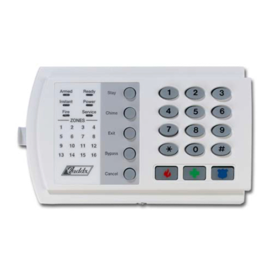
[*] in the current segment Enters the previous Returns to the “loca tion” Advances to the next programming “location” just programmed programming “location” NX-4-EUR Installation manual Page 28 02/07/06... - Page 29 When a LED is “ON”, a feature is enabled, when “OFF” the feature is disabled. For example, with the 1, 5 & 7 LED’s “ON”, quick arm, audible keypad panic and keypad auxiliary 2 are enabled. NX-4-EUR Installation manual Page 29 02/07/06...
-
Page 30: Programming The Nx-4 Control Panel Via Lcd Keypad
To proceed to the next location, press the [Police] key. To return to the previous location, press the [Fire] key. To re-enter the last location, press the [Medic] key. NX-4-EUR Installation manual Page 30 02/07/06... - Page 31 CLOSET GLASSBREAK MOTION SKYLIGHT WAREHOUSE DELAY GUEST NORTH SLIDING WEST HALL NURSERY SMALL WINDOW DETECTOR HEAT OFFICE SMOKE WING DINING HOLDUP PANIC SOUND WIRELESS DOOR HOUSE PANTRY SOUTH YARD DOWN INFRARED PHONE STAIRS ZONE NX-4-EUR Installation manual Page 31 02/07/06...
-
Page 32: Exiting The Program Mode
The enrolling process takes about 12 seconds, during this time the “Service Screen” will be displayed. If a module has been enrolled but it is not detected by the control, the “Service Screen” will be displayed. NX-4-EUR Installation manual Page 32 02/07/06... -
Page 33: Important Remarks
When this option is enabled (see location 23, segment 1), the NX-4 will disable the keypad for 60 seconds, and will communicate a tamper signal to the central station if 30 key presses are entered without producing a valid code. NX-4-EUR Installation manual Page 33 02/07/06... -
Page 34: Clc/Ts 50131-3 Compliancy
Maximum load taken from the AUX OUT should not exceed the values as stated in the table below (EN-50131-6:1997 and EN50131-1:1997 table 16) battery NX-4 NX-6 NX-8 Max current consumpt. 77mA 96mA 105mA Max current AUX OUT 7.2Ah 480mA 460mA 450mA Max current AUX OUT 18Ah 570mA 560mA 550mA NX-4-EUR Installation manual Page 34 02/07/06... -
Page 35: Control Panel Programming Locations
Factory default is “8” and the communicator will make 8 attempts to the first number. There will be a waiting time of 12 seconds between the first two dial attempts, and a waiting time of 60 seconds between each subsequent dial attempt. NX-4-EUR Installation manual Page 35 02/07/06... -
Page 36: Format Selections
If you want to trigger a “kiss-off” signal via a GSM, you have to take into account that this function is network provider dependent. Entering a valid user code on a keypad will stop the dialler when using the siren or vocal format. NX-4-EUR Installation manual Page 36 02/07/06... -
Page 37: Reporting Events To Phone Number 1
Auxiliary power over-current, and restore Wireless sensor missing and restore Wireless sensor low battery and restore Expander trouble and restore (keypads are considered as expanders) Fail to communicate Alarm restore Tamper restore LOCATION 5 - Reserved NX-4-EUR Installation manual Page 37 02/07/06... -
Page 38: Telephone Number 2
The first two attempts will be made to phone N°2, the next two attempts to phone N°1, then repeating until the total number of attempts designated in segment 1 is completed. NX-4-EUR Installation manual Page 38 02/07/06... -
Page 39: Reporting Events To Phone Number 2
Auxiliary power overcurrent, and restore Wireless sensor missing and restore Wireless sensor low battery and restore Expander trouble and restore (keypads are considered as expanders) Fail to communicate Alarm restore Tamper restore LOCATION 11 - Reserved NX-4-EUR Installation manual Page 39 02/07/06... -
Page 40: Telephone Number 3
The first two attempts will be made to phone N°3, the next two attempts to phone N°2, then repeating until the total number of attempts designated in segment 1 is completed. NX-4-EUR Installation manual Page 40 02/07/06... -
Page 41: Reporting Events To Phone Number 3
Auxiliary power overcurrent, and restore Wireless sensor missing and restore Wireless sensor low battery and restore Expander trouble and restore (keypads are considered as expanders) Fail to communicate Alarm restore Tamper restore LOCATION 17 - Reserved NX-4-EUR Installation manual Page 41 02/07/06... -
Page 42: Special Formats
“5”, options 1 and 3 must be selected. Ex: when the value 10 is programmed on segment 4 and a pulse format of 20 PPS is used, the inter-digit time is 10/20 = 0.5 sec. NX-4-EUR Installation manual Page 42 02/07/06... -
Page 43: Download Parameters
Four-second delays can be obtained anywhere in the sequence by programming a “13” in the appropriate delay location. Note: a zero is programmed as a “0”. WARNING: YOU SHOULD ALWAYS CHECK THAT THE CALLBACK PHONE NUMBER IS ACCURATE BEFORE DISCONNECTING. NX-4-EUR Installation manual Page 43 02/07/06... -
Page 44: Feature And Report Selections (For Partition 1)
On: tamper when sensor lost if armed On : enables instant STAY mode (toggle) On: arming allowed with tamper memory / communication failure/ expander trouble On : arming allowed with battery trouble On: keyswitch zone arms in STAY mode NX-4-EUR Installation manual Page 44 02/07/06... -
Page 45: Entry/Exit Timers
Valid entries are 10-255 seconds. Segment 4 Exit time 2 This is the exit time that will be used for all zones designated as delay 2. Valid entries are 10-255 seconds. Segment 5 Reserved Segment 6 Reserved NX-4-EUR Installation manual Page 45 02/07/06... -
Page 46: Zone Configurations And Partition Selection
This zone type will arm and disarm the partition or partitions of the control panel where it is resident, every time the zone is shorted. Keyswitch arming will report as user 99. This zone type can only belong to 1 partition. NX-4-EUR Installation manual Page 46 02/07/06... - Page 47 This zone creates an instant alarm whenever it is tripped during the arming state of the control panel. This zone will bypass automatically, if enabled in segment 1 of location 23, or when this system is armed in the “Stay” mode. NX-4-EUR Installation manual Page 47 02/07/06...
- Page 48 (e.g. flashing zone LED’s, and changed READY LED). A medical report will be sent to the CMS. Note: all zone configurations are programmed for double end of line resistor configuration, except for DAY ZONE, FIRE, 24H AUDIBLE SUPERVISED and END OF LINE RESISTOR DEFEAT. NX-4-EUR Installation manual Page 48 02/07/06...
-
Page 49: General Options
On: if autotest report is enabled On: if start/end programming report is enabled On: if end download report is enabled On: if sensor low battery report is enabled On: if sensor missing report is enabled NX-4-EUR Installation manual Page 49 02/07/06... - Page 50 On: if keypad sounds when a low battery is detected On: if keypad sounds during cross zone trip time On: if keypad sounds for zone and box tampers On: if keypad sounds for Emergency keys On: if keypad sounds for Expander trouble NX-4-EUR Installation manual Page 50 02/07/06...
- Page 51 DIGITS. If this option is not enabled in location 41, the last 2 segments (digits) will be ignored. With the NX-4 disarmed, the “Go To Program Code” can be used to enter the Program Mode. NX-4-EUR Installation manual Page 51...
- Page 52 41, THIS CODE MUST CONTAIN SIX (6) DIGITS. If the 6-digit option is not enabled in location 41, the last 2 digits will be ignored. If the duress code is programmed, it will work for all partitions. NX-4-EUR Installation manual Page 52 02/07/06...
-
Page 53: Programming The Outputs
(relay 2) Segment 2 Program the timing from 0-255 (minutes or seconds, depending on the data programmed in segment 2, location 46). Programming a “0” makes the output follow the event LOCATION 49-50 - Reserved NX-4-EUR Installation manual Page 53 02/07/06... - Page 54 (See “Programming the LED Keypads”) ♣ Events 49 and 50 require one or more of the following to operate: wireless receivers or cardreaders. If set to follow condition, these events will be 1 second. NX-4-EUR Installation manual Page 54 02/07/06...
-
Page 55: Etup For Auto Test Auto Arm And Opening Closing Times
Note: Opening time must be earlier than closing time so that auto arm, Aux. outputs, or code authorisation can function properly. Segment 1 Program the hour of the closing / auto arm time Segment 2 Program the minutes after the hour of the closing / auto arm time NX-4-EUR Installation manual Page 55 02/07/06... - Page 56 If the zone restores, it will be unbypassed and active in the system. Segment 1 Auto arming on Sunday Auto arming on Monday Auto arming on Tuesday Auto arming on Wednesday Auto arming on Thursday Auto arming on Friday Auto arming on Saturday Disable retry timer NX-4-EUR Installation manual Page 56 02/07/06...
-
Page 57: Communicator Codes For Slow Speed Formats Only
(1-8) will be reported (e.g. zone 1 = 1, zone 8 = 8). To report a restore, the restore code of location 56 will be used. Segment 1 Zones 1-15, “Tamper Code” Segment 2-8 Reserved NX-4-EUR Installation manual Page 57 02/07/06... - Page 58 “Auxiliary 1” (FIRE) is enabled in the partition feature selection. Segment 1 contains the tens digit; segment 2 contains the ones digit. For a 3+1 format, only the segment 1 digit (tens) will be sent. NX-4-EUR Installation manual Page 58 02/07/06...
- Page 59 Segment 2 contains the ones digit of the “AC Fail Reporting”. Segment 3 contains the tens digit of the “AC Fail Restore”. Segment 4 contains the ones digit of the “AC Fail Restore”. For a 3+1 format, only the segment 1 resp. segment 3 digit (tens) will be sent. NX-4-EUR Installation manual Page 59 02/07/06...
- Page 60 Location 75 contains the tens and ones digits for a 4+2 and 3+1 format that will be sent if the “Fail To Communicate Reporting” is enabled. Segment 1 contains the tens digit, and segment 2 contains the ones digit. For a 3+1 format, only the segment 1 digit (tens) will be sent. NX-4-EUR Installation manual Page 60 02/07/06...
- Page 61 Location 79 contains the tens and ones digits for a 4+2 and 3+1 format that will be sent if “Autotest” or “Manual Test” is enabled. Segment 1 contains the tens digit, and segment 2 contains the ones digit. For a 3+1 format, only the segment 1 digit (tens) will be sent. NX-4-EUR Installation manual Page 61 02/07/06...
- Page 62 Reporting”. As ones digit, the user number (1-8) of the user who cancelled, will be sent. If you need to report cancels with a unique code per user, Contact ID or SIA format must be used. LOCATIONS 84-109 - RESERVED NX-4-EUR Installation manual Page 62 02/07/06...
-
Page 63: Programming Zone Configuration Groups
On: if configuration group is a Cross Zone On: enables Dialler Delay zone. (See location 40) On: if configuration group will use swinger shutdown. (See location On: enables Restore reporting On: enables Listen-In. (See location 40) NX-4-EUR Installation manual Page 63 02/07/06... - Page 64 121-122. The zone ID will be the zone that is in alarm. This location is not used for slow speed formats (like 4+2 and 3+1). This location may also contain the alarm report code for the Robofon format (value 00-99). NX-4-EUR Installation manual Page 64 02/07/06...
- Page 65 Robofon format (value 00-99). LOCATION 123 - CONFIGURATION GROUP 7 CHARACTERISTIC SELECT (5 segments, feature selection data) Use the “Configuration Group Characteristic Selections” described in Location 111. NX-4-EUR Installation manual Page 65 02/07/06...
- Page 66 121-122. The zone ID will be the zone that is in alarm. This location is not used for slow speed formats (like 4+2 and 3+1). This location may also contain the alarm report code for the Robofon format (value 00-99). NX-4-EUR Installation manual Page 66 02/07/06...
- Page 67 Robofon format (value 00-99). LOCATION 137 - CONFIGURATION GROUP 14 CHARACTERISTIC SELECT (5 segments, feature selection data) Use the “Configuration Group Characteristic Selections” described in Location 111. NX-4-EUR Installation manual Page 67 02/07/06...
- Page 68 121-122. The zone ID will be the zone that is in alarm. This location is not used for slow speed formats (like 4+2 and 3+1). This location may also contain the alarm report code for the Robofon format (value 00-99). NX-4-EUR Installation manual Page 68 02/07/06...
- Page 69 Robofon format (value 00-99). LOCATION 151 - CONFIGURATION GROUP 21 CHARACTERISTIC SELECT (5 segments, feature selection data) Use the “Configuration Group Characteristic Selections” described in Location 111. NX-4-EUR Installation manual Page 69 02/07/06...
- Page 70 Robofon format (value 00-99). LOCATION 159 - CONFIGURATION GROUP 25 CHARACTERISTIC SELECT (5 segments, feature selection data) Use the “Configuration Group Characteristic Selections” described in Location 111. NX-4-EUR Installation manual Page 70 02/07/06...
- Page 71 Robofon format (value 00-99). LOCATION 165 - CONFIGURATION GROUP 28 CHARACTERISTIC SELECT (5 segments, feature selection data) Use the “Configuration Group Characteristic Selections” described in Location 111. NX-4-EUR Installation manual Page 71 02/07/06...
- Page 72 Location 206 selects which days the system will auto disarm. Segment 1 Auto disarming on Sunday Auto disarming on Monday Auto disarming on Tuesday Auto disarming on Wednesday Auto disarming on Thursday Auto disarming on Friday Auto disarming on Saturday Reserved NX-4-EUR Installation manual Page 72 02/07/06...
- Page 73 When changing the country code during programming, all existing programming will be cleared to the defaults for that country (see location 213). Code Country No country (default) Holland Belgium / Poland Sweden Italy Spain Greece South Africa Israel Reserved Turkey NX-4-EUR Installation manual Page 73 02/07/06...
-
Page 74: Programming Worksheets
NX-4 P ROGRAMMING WORKSHEETS (Factory defaults for NX-4-EUR (BEL/POL) are in bold italic text) DESCRIPTION DEFAULT PROGRAMMING DATA PHONE 1 14-14-14-14-14-14-14-14-14-14-14- 14-14-14-14-14-14-14-14-14 10 – 10 – 10 – 10 – 10 – 10 PHONE 1, ACCOUNT CODE PHONE 1, REPORTING FORMAT... - Page 75 Enables two-call answering machine defeat Reserved Requires callback before downloading Shutdown control panel Lock out local programming Lock out communicator programming Lock out download section Enables callback at autotest interval CALLBACK PHONE NUMBER 14-14-14-14-14-14-14-14-14-14-14- 14-14-14-14-14-14-14-14-14 NX-4-EUR Installation manual Page 75 02/07/06...
- Page 76 Segment 1 (Entry Time 1) Segment 2 (Exit Time 1) Segment 3 (Entry Time 2) Segment 4 (Exit Time 2) Reserved Reserved ZONES 1-8, CONFIGURATION GROUPS 3-5-6-6-6-6-6-6 Reserved Reserved Reserved Reserved Reserved Reserved Reserved Reserved Reserved Reserved NX-4-EUR Installation manual Page 76 02/07/06...
- Page 77 Enable zone activity in hours (not in days) Enable first alarm logic Enable log protection Disable Clean Me report Siren output is steady in case of fire alarm User code will reset tamper memory NX-4-EUR Installation manual Page 77 02/07/06...
- Page 78 Enables six digit code option. All arm/disarm/Go to program codes require six digits Requires valid user code entry so that [*]-[9]-[8] and [*]-[9]-[9] functions can work Enables Auto Cancel / Abort Reserved On: keypad shutdown mode On: user authorization to enter program mode Reserved Reserved NX-4-EUR Installation manual Page 78 02/07/06...
- Page 79 Program the minutes after the hour of the opening time CLOSING TIME / AUTO ARMING TIME Segment 1 Program the hour of the closing time / auto arming time Segment 2 Program the minutes after hour of closing / auto arming time NX-4-EUR Installation manual Page 79 02/07/06...
- Page 80 LOW BATTERY / LOW BATTERY RESTORE 0-0-0-0 POWER SHORT / POWER SHORT RESTORE 0-0-0-0 BELL TAMPER / BELL TAMPER RESTORE 0-0-0-0 Reserved Reserved 0-0-0-0 EXPANDER TROUBLE / EXPANDER TROUBLE RESTORE FAILURE TO COMMUNICATE LOG FULL COMMUNICATOR CODE NX-4-EUR Installation manual Page 80 02/07/06...
- Page 81 CONFIGURATION GROUP 5 ALARM EVENT CODE CONFIGURATION GROUP 5 CHARACTERISTIC SELECT 457-125-25678 CONFIGURATION GROUP 6 ALARM EVENT CODE CONFIGURATION GROUP 6 CHARACTERISTIC SELECT 0-125-25678 CONFIGURATION GROUP 7 ALARM EVENT CODE CONFIGURATION GROUP 7 CHARACTERISTIC SELECT 2-5-278 NX-4-EUR Installation manual Page 81 02/07/06...
- Page 82 CONFIGURATION GROUP 28 ALARM EVENT CODE CONFIGURATION GROUP 28 CHARACTERISTIC SELECT 0-125-25678-1 CONFIGURATION GROUP 29 ALARM EVENT CODE CONFIGURATION GROUP 29 CHARACTERISTIC SELECT 0-125-5678-2 CONFIGURATION GROUP 30 ALARM EVENT CODE CONFIGURATION GROUP 30 CHARACTERISTIC SELECT 24-125-278 170- RESERVED 0-0-0-0-0-0-0-0 NX-4-EUR Installation manual Page 82 02/07/06...
-
Page 83: Board Installation
Note: For installation, service or maintenance a set of screwdrivers is required (not included). Note: The cabinet needs to be closed with a screw or with an optional cam lock (CLC/TS 50131-3). NX-4-EUR Installation manual Page 83 02/07/06... -
Page 84: Wiring Diagram
NX-4 W IRING DIAGRAM AUDIO TAP Pin 1 NetworX Bus PROGRAM Pin 1 NX-4-EUR Installation manual Page 84 02/07/06... -
Page 85: Terminal Description
Connect to one side of zone 2 loop. Connect the other side to the COM terminal. Open or short causes alarm. Common (-) terminal for zones 1 & 2. ZONE 1 Connect to one side of zone 1 loop. Connect the other side to COM terminal. Open or short causes alarm. NX-4-EUR Installation manual Page 85 02/07/06... -
Page 86: Technical Specifications
Current consumption in alarm - 1 zone in alarm, sounder/lighting ON 42 mA 42 mA 42 mA - Maximum (all LED’s ON, sounder ON) 90 mA 110 mA 130 mA Weight 228 g 230 g 232 g NX-4-EUR Installation manual Page 86 02/07/06... -
Page 87: Technical Specifications Nx-1308, Nx-1316, Nx-1324
25 mA - Nominal (quiescient, maximum lighting) 48 mA Current consumption in alarm - 1 zone in alarm, sounder/lighting ON 65 mA - Maximum (all LED’s ON, sounder ON) 110 mA Weight 290 g NX-4-EUR Installation manual Page 87 02/07/06... -
Page 88: Appendix 1: Reporting Fixed Codes In Contact-Id And Sia
PARENTHESES, THE ZONE WILL BE “0”. SEE APPENDIX 3 FOR THE DEVICE NUMBERS. * The character transmitted in this slot will be the first character from the event code of the zone that is bypassed or in trouble (see locations 110 - 169). NX-4-EUR Installation manual Page 88 02/07/06... -
Page 89: Appendix 2: Reporting Zone Codes In Sia Or Contact Id
Burglary Alarm Burglary Alarm Untyped Alarm Holdup Alarm Medical Alarm Panic alarm Tamper Alarm Periodic Test Gas Alarm Heat Alarm Water Alarm Emergency Alarm Sprinkler Alarm Freeze Alarm Heat Alarm Restore Manual Fire Alarm NX-4-EUR Installation manual Page 89 02/07/06... - Page 90 Day/Night Alarm Non Burglary 24 Hour Duress Alarm Medical Alarm Audible Panic Alarm Tamper Alarm Periodic Test Gas Detected High Temp Water Leakage General Alarm General Alarm Low Temp Heat Alarm Restore Manual Fire Alarm NX-4-EUR Installation manual Page 90 02/07/06...
-
Page 91: Appendix 3: Expander Numbers For Reporting Expander Trouble
Keypads KEYPAD PART 1 Wireless receiver NX-448E Wireless receiver DIP 1 DIP 2 DIP 3 Expander number reported Output module NX-507E or NX-508E Output module DIP 1 DIP 2 DIP 3 Expander number reported NX-4-EUR Installation manual Page 91 02/07/06... -
Page 92: Ce Declaration
CE D ECLARATION NX-4-EUR Installation manual Page 92 02/07/06... - Page 93 NX-4-EUR Installation manual Page 93 02/07/06...
- Page 94 NX-4-EUR Installation manual Page 94 02/07/06...
- Page 95 NX-4-EUR Installation manual Page 95 02/07/06...
- Page 96 NX-4-EUR Installation manual Page 96 02/07/06...
- Page 97 NX-4-EUR Installation manual Page 97 02/07/06...
- Page 98 NX-4-EUR Installation manual Page 98 02/07/06...
- Page 99 NX-4-EUR Installation manual Page 99 02/07/06...
- Page 100 EMEA Distribution is a division of GE Security EMEA bvba COPYRIGHT ©2006 © GE Security EMEA bvba. All rights reserved. GE Security EMEA bvba grants the right to reprint this manual for internal use only. GE Security EMEA bvba reserves the right to change information without notice.