
Related Manuals for GE NetworX NX-4V2


Summary of Contents for GE NetworX NX-4V2
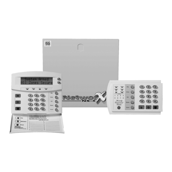
- Page 1 ™ NetworX Series NX-4V2 Control Panel Installation and Startup WWW.DIYALARMFORUM.COM...
- Page 2 GE Security. This document contains proprietary information of GE Security and is furnished to its customer solely to assist that customer in the installation, testing, operations, and/or maintenance of the equipment described. This document shall not be reproduced in whole or in part nor shall its contents be disclosed to any third party without the written approval of GE Security.
-
Page 3: Table Of Contents
Table of Contents GENERAL DESCRIPTION................................. 4 ORDERING INFORMATION ................................4 III. BOARD INSTALLATION ................................... 4 WIRING DIAGRAM .................................... 5 TERMINAL DESCRIPTIONS ................................6 NETWORX KEYPAD MAXIMUM WIRE RUN ..........................6 PROGRAMMING THE LED KEYPADS ............................7 KEYPAD ADDRESS ..................................... 7 CHANGING USER CODES: ................................. -
Page 4: General Description
GENERAL DESCRIPTION The NetworX NX-4V2 represents a new approach to security systems design. Drawing on our experience in the world market as the largest exporter of USA manufactured controls, we have developed the most flexible, durable, and user-friendly control ever seen in our industry. -
Page 5: Wiring Diagram
WIRING DIAGRAM WWW.DIYALARMFORUM.COM NX-4V2 Control... -
Page 6: Terminal Descriptions
TERMINAL DESCRIPTIONS TERMINAL DESCRIPTION House Telephone Ring (Grey). Telephone Ring (Red). Telephone Tip (Green). House Telephone Tip (Brown). AC input. Connect to a 16.5V 40 or 50 VA Class ll U.L. approved transformer. EARTH Earth Ground. Connect to a cold water pipe or a 6 to 10 foot driven rod. Connect negative lead of low current device [relay, LED (install 1KΩ... -
Page 7: Programming The Led Keypads
PROGRAMMING THE LED KEYPADS KEYPAD ADDRESS This section describes how to program the address of each keypad as well as the options that are available. The address of the keypad is important because this is how the panel supervises the keypads. The factory default for the Master code is [1]-[2]-[3]-[4] when using a 4-digit code or [1]-[2]-[3]-[4]-[5]-[6] for a 6-digit code. -
Page 8: Programming The Control
ATTRIBUTES IF LED 8 IS OFF ATTRIBUTES IF LED 8 IS ON Reserved Activate output #1 Arm Only Activate output # 2 Arm Only After Close Window Activate output # 3 Master arm/disarm (can program other codes) Activate output # 4 Arm/disarm code Arm/disarm Allowed to bypass zones (see location 23) -
Page 9: Programming Data Types
VIII. PROGRAMMING DATA TYPES Programming data is always one of two types. One type of data is numerical and can take on values from 0 to 15 or 0 to 255 depending on the location's segment. The other type of data is a feature selection type. Feature selection data is used to turn features on or off. Examples are shown on page 10. -
Page 10: Programming Examples
PROGRAMMING EXAMPLES FIGURE1 (Numerical Data) Zone 1 LED = 1 Zone 2 LED = 2 Data = 9 Data = 66 Zone 4 LED = 8 Zone 7 LED = 64 To change data in a Pressing [#] will exit a segment, enter the location without data followed by [ ]... -
Page 11: Loading Factory Defaults
LOADING FACTORY DEFAULTS To load the factory defaults, enter the program mode using the procedure on page 8, then type [9]-[1]-[0]-[#]. The keypad will beep 3 times indicating that the loading is in progress. The loading takes about 6 seconds. ENROLLING MODULES AND KEYPADS For supervision purposes, the NX-4V2 has the ability to automatically find and store in its memory, the presence of all keypads, zone expanders, wireless receivers, and any other module connected to the data terminal. -
Page 12: Reporting Events To Phone Number 1
DIAL ATTEMPTS/BACKUP CONTROL FOR PHONE 1 2 ... numerical Segment 1- Dial attempts: Location 3, Segment 1 is used to enter the number of dial attempts (1 to 15 Attempts) the communicator will make to Phone 1 before ending the notification process. Factory default is "8" and the communicator will make eight (8) attempts to the first number. -
Page 13: Reporting Events To Phone Number 2
DIAL ATTEMPTS/BACKUP CONTROL FOR PHONE 2 2..... numerical Segment 1, Dial attempts: Segment 1 of Location 9 is used to enter the number of dial attempts (1 to 15 attempts) the communicator will make to Phone 2 before ending the notification process. Factory default is "8" and the communicator will make the same number of attempts as those programmed in location 3. -
Page 14: Reporting Events To Phone Number 3
Segment 2, Phone 3 Backup Control: Programming a "0" in Segment 2 of this location will cause the NX-4V2 to make the designated number of attempts to Phone 2 before setting the "Fail To Communicate" condition and stop reporting. Programming a "1" in this segment will cause the NX-4V2 to stop trying to communicate after the designated number of attempts have been made to Phone 3. - Page 15 DOWNLOAD CONTROL 1..... feature select Location 21 contains the feature selections for the controlling of download sessions. The following features can be enabled or disabled using this location. (Refer to Glossary beginning on page 35) Segment 1: Options 4, 5, 6, 1 = On enables two call answering machine defeat.
-
Page 16: Default Zone Types (Configurations)
ENTRY / EXIT TIMERS 6 .... numerical Location 24 is used to program the Entry/Exit times. There are 2 separate Entry/Exit times. Segment 1, Entry time 1: This is the entry time that will be used when a delay 1 zone type initiates an entry delay. Valid entries are 30-255 seconds. - Page 17 DATA DESCRIPTION OF DEFAULT ZONE TYPES ENTRY/EXIT DELAY 2 WITH TAMPER ENABLED-A trip will start entry delay 2. The lack of a trip during exit delay will enable the Automatic Bypass or Instant mode if so programmed. This zone type can be used to enable tamper on a wireless transmitter.
- Page 18 Segment 3: 1 = On if Box Tamper report enabled. 2 = On if AC Fail reporting enabled. 3 = On if Low Battery reporting enabled. 4 = On if Aux. Power Overcurrent report enabled. 5 = On if Siren Supervision report enabled. 6 = On if Telephone Line Cut report enabled.
- Page 19 SYSTEM TIMERS 14... numerical Location 40 contains the duration of various system timing functions. Example: If you desire the duration of the Dynamic Battery Test to be 30 minutes, you should program [3]-[0]-[r] in segment 1 of this location. The [3]-[0] is the number of minutes, and the [r] stores the data and moves to the next segment of this location.
- Page 20 SLOW COMMUNICATOR FORMAT CODES AUXILIARY OUTPUT 1 - 2 SPECIAL TIMING 2 .... feature select Location 46 contains special timing feature activation for the four auxiliary outputs. Segment 1 corresponds to output 1; Segment 2 corresponds to output 2. Segments 1 - 2: 1 = On if output should be timed in minutes;...
- Page 21 OPENING TIME 2..... numerical Location 52 contains the time in 24 hour format the NX-4V2 enables codes designated as arm only after closing. This time is only valid on those days programmed in location 54. Note: Opening time must be earlier than closing time for Auto Arm, Aux. Outputs, or Code Authorization to function properly.
- Page 22 LOCATIONS 56- 83 ARE ONLY USED WHEN REPORTING EVENTS TO A PAGER OR USING A SLOW FORMAT SUCH AS 4+2. When using Contact ID or SIA, there is no need to program these locations. The digit programmed in each of the following locations will be sent as the upper HEX digit in place of the alarm event code. The zone ID or user ID will always be reported as the lower HEX digit (1-F).
- Page 23 EXPANDER TROUBLE / RESTORE COMM CODE 4..... numerical Location 74 contains the digits for a 4+2 format that will be sent if "Expander Trouble Reporting" is enabled. Segments 1 & 2 contain the digits of the "Expander Trouble Reporting". Segments 3 & 4 contain the digits of the "Expander Trouble Restore". (Box on pg 22.) FAIL TO COMMUNICATE COMMUNICATOR CODE 2.....
- Page 24 5 = On if Zone Type can be bypassed. 6 = On if Zone Type is included in the group shunt. 7 = On if Zone Type is force armable. 8 = On if Zone Type is entry guard. Segment 3: On enables Fast Loop Response.
- Page 25 ZONE TYPE 8 ALARM EVENT CODE 1..... numerical Location 124 contains the event code sent for a Contact ID or SIA report. The desired event code should be chosen from the list on page 39. The zone ID will be that zone that is in alarm. If 4+2 format is being used, refer to Location 110 on page 23 for details. ZONE TYPE 8 CHARACTERISTIC SELECT 5.....
- Page 26 ZONE TYPE 18 ALARM EVENT CODE 1 .... numerical Location 144 contains the event code sent for a Contact ID or SIA report. The desired event code should be chosen from the list on page 39. The zone ID will be that zone that is in alarm. If 4+2 format is being used, refer to Location 110 on page 23 for details. ZONE TYPE 18 CHARACTERISTIC SELECT 5 ....
- Page 27 ZONE TYPE 27 CHARACTERISTIC SELECT 5..... feature select Use "Zone Type Characteristic Selections" described in Location 111, page 23 ZONE TYPE 28 ALARM EVENT CODE 1..... numerical Location 164 contains the event code sent for a Contact ID or SIA report. The desired event code should be chosen from the list on page 39.
-
Page 28: Programming Worksheets
XIV. PROGRAMMING WORKSHEETS (Factory defaults for segments are in bold italics text and "Quick Start" locations are identified with the symbol.) DESCRIPTION DEFAULT PROGRAM DATA PHONE 1 14-14-14-14-14-14-14-14-14-14- __ __ __ __ __ __ __ __ __ __ 14-14-14-14-14-14-14-14-14-14 __ __ __ __ __ __ __ __ __ __ PHONE 1, ACCOUNT CODE 10 - 10 - 10 - 10 - 10 - 10 _ _ _ _ _ _... - Page 29 DESCRIPTION DEFAULT PROGRAM DATA DOWNLOAD ACCESS CODE 8-4-8-0-0-0-0-0 _ _ _ _ _ _ _ _ RINGS TO ANSWER DOWNLOAD DOWNLOAD CONTROL Segment 1 (Circle Numbers To Program) 1 = Enables two call answering machine defeat 2 = Enables tone sniff answering machine defeat 3 = Requires callback before downloading 4 = Shutdown control panel 5 = Lock out local programming...
- Page 30 DESCRIPTION DEFAULT PROGRAM DATA L 37 Segment 3 (Circle numbers to program) 1 = Box Tamper report enabled. 2 = AC Fail report enabled. 3 = Low Battery report enabled. 4 = Auxiliary power over current report enabled. 5 = Siren supervision report enabled. 6 = Telephone Line Cut report enabled.
- Page 31 DESCRIPTION DEFAULT PROGRAM DATA GO TO PROGRAM CODE 9-7-1-3-0-0 _ _ _ _ _ _ GO TO PROGRAM CODE & AUTHORIZATION Segment 1 (Circle numbers to program) 1 = Reserved. 2 = Enables "Go To Program Code" as an arm only code. 3 = Enables "Go To Program Code"...
- Page 32 COMMUNICATOR CODES FOR SLOW SPEED FORMATS ONLY The digit programmed in each of the following locations will be sent as the upper HEX digit in place of the alarm event code. The zone ID or user ID will always be reported as the lower HEX digit (1-F). For example, if the zone ID or user ID is 6, the 4+2 lower digit will be “6”.
- Page 33 LOCATIONS 112 – 169 EVEN NUMBERED ..Contains the event code sent for Contact ID or SIA and chosen from the list on pg 16. 4+2 Format Note: If 4+2 format is being used, the number programmed in this location will be sent as the upper hex digit. The digit should be from 1 to 15 when using 4+2 formats.
- Page 34 DESCRIPTION DEFAULT PROGRAMMING DATA ZONE TYPE 30 CHARACTERISTIC SELECT 5-1245-5678-1-0 __ __ __ __ __ 170-205 RESERVED DAYS OF THE WEEK "AUTO DISARMING" WILL OCCUR Sunday Monday Tuesday Wednesday Thursday Friday Saturday Reserved Segment 1 ZONE WORKSHEET NOTES WWW.DIYALARMFORUM.COM NX-4V2 Control...
-
Page 35: Glossary
GLOSSARY Abort If enabled, the NX-4V2 will wait the programmed number of seconds in location 40 prior to sending an alarm. During this delay time, the “Cancel” LED will flash. To abort the report, type in a code and press the Cancel key. The LED will extinguish. If the report is not aborted within the allotted time, the LED will extinguish when the report is sent. - Page 36 Dual / Split / Multiple Reports The NX-4V2 can send communication reports to three different phone numbers for dual, split or multiple reports selectable by event. (Loc 4, 10, & 16, pg 12, 13, 14) Duress Code If a duress code is programmed the NX-4V2 will send a duress signal whenever the panel is armed or disarmed with this code. If open/close reports are sent, the user code will be 254.
- Page 37 LED Extinguish This feature will extinguish all LEDs on the keypad, except the "Power" LED, after 60 seconds without a keypress. Pressing any numeric key will illuminate all LED=s. (Loc 23, pg 15) Local Programming Lockout This feature will disable programming of all locations or specified locations from the keypad. (Loc 21, pg 15) Log Full Report A report can be sent to the central station when the event log is full.
- Page 38 Two Call Answering Machine Defeat This is not recommended for commercial applications. If enabled, to defeat an answering machine, two telephone calls must be made to the premises. On the first call, let the phone ring one or two times. The control panel will detect these rings and start a 45-second timer, during which, the control panel will answer the next call on the first ring.
-
Page 39: Xvi. Appendix 1
XVI. APPENDIX 1 REPORTING FIXED CODES IN CONTACT ID AND SIA The table below list the event codes sent for the following reports (if enabled) when using CONTACT ID or SIA formats. REPORT CONTACT ID AC FAIL (device number) ............301...........AT AC RESTORE (device number).......... -
Page 40: Xvii. Appendix 2
XVII. APPENDIX 2 REPORTING ZONE CODES IN SIA OR CONTACT ID The NX-4V2 has the ability to report SIA level 1 transmissions to either or both phone numbers. Each report in SIA consists of an Event Code and a Zone or User ID. The Zone ID will be the zone number that is in alarm. The event code will come from the chart below and be programmed in the zone type event code. -
Page 41: Xviii. Appendix 3
XVIII. APPENDIX 3 EXPANDER NUMBERS FOR REPORTING EXPANDER TROUBLE The tables below list the device numbers that will be reported for trouble conditions. Device Device # reported NX-4V2 Control Panel See page 39 for possible report codes. NX-534E Two Way Listen-In NX-540E “Operator”... -
Page 42: Local Telephone Company Interface Information
LOCAL TELEPHONE COMPANY INTERFACE INFORMATION TELEPHONE CONNECTION REQUIREMENTS Except for telephone company provided ringers, all connections to the telephone network shall be made through standard plugs and standard telephone company provided jacks or equivalent in such a manner as to allow for immediate disconnection of the terminal equipment. -
Page 43: Notices
XXII. NOTICES Network Compatibility Declaration (Applies to products which have the CE mark attached) We declare under our sole responsibility that this product is designed to work with the networks in the countries marked with a check ( ) and may have interworking problems with the Declaration Of Conformity countries that are not checked. -
Page 44: Underwriters Laboratories Information
XXIII. UNDERWRITERS LABORATORIES INFORMATION The NetworX NX-4V2 holds the following listings from Underwriters Laboratories (US and Canadian): UL294 Access Control System Units UL365 Police Station Connected Burglar Alarms UL609 Local Grade A Mercantile, Police Station Connect with Basic Line Security... - Page 45 MINIMUM SYSTEM CONFIGURATIONS FOR UL INSTALLATIONS (Residential Fire, Residential Burglary, Commercial Burglary) • The NetworX NX-4V2 panel is necessary to initiate Residential and Commercial installations. • At least one compatible keypad is needed for all applications. • At least one bell fixture is required for all applications, except Grade C Central Station. For Grade A Local, the AD10-12 bell and Grade A bell housing shall be used.
-
Page 46: Ansi / Sia Cp-01 Requirements
WWW.DIYALARMFORUM.COM... - Page 47 NOTES WWW.DIYALARMFORUM.COM...
-
Page 48: Specifications
XXV. SPECIFICATIONS OPERATING POWER 16.5 VAC 40, or 50 VA Transformer AUXILIARY POWER w/25 VA Transformer 12 VDC Regulated 500 mA w/40 or 50 VA Transformer 12 VDC Regulated 1 AMP LOOP RESISTANCE Standard Loop 300 Ohms Maximum BUILT-IN SIREN DRIVER 2-tone (Temporal and Yelp) LOOP RESPONSE Selectable 50mS or 500mS...