Endress+Hauser FMU 40 Manual
Ultrasonic level measurement
prosonic m
Hide thumbs
Also See for FMU 40:
- Description of functions (88 pages) ,
- Description of instrument functions (80 pages) ,
- Description (80 pages)
Advertisement
Table of Contents
- 1 Function and System Design
- 2 Power Supply
- 3 Performance Characteristics
- 4 Installation Conditions
- 5 Ambient Conditions
- 6 Process Conditions
- 7 Mechanical Construction
- 8 Human Interface
- 9 Certificates and Approvals
- 10 Ordering Information
- 11 Supplemental Documentation
- 12 Endress+Hauser
- Download this manual
Technical
Information
TI 365F/24/ae
Ultrasonic Level Measurement
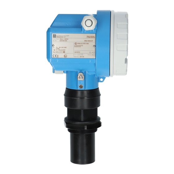
prosonic M FMU 40/41/43
Compact transmitters for non-contact level
measurement of fluids, pastes and coarse
bulk materials
FMU 40
Application
The compact Prosonic M transmitters are
used for continuous, non-contact level
measurement in fluids and coarse bulk
materials.
Additionally, the sensors can be used for
flow measurement in open channels and
measuring weirs.
The following interfaces are available for
system integration:
• HART
®
(standard), 4 to 20 mA
• PROFIBUS-PA
• Foundation Fieldbus
The maximum measuring range for
Prosonic M sensors are:
• FMU 40:
– Fluids, 16 feet (5 m)
– Bulk solids, 6 feet (2 m)
• FMU 41:
– Fluids, 26 feet (8 m)
– Bulk solids, 12 feet (3.5 m)
• FMU 43:
– Fluids, 50 feet (15 m)
– Bulk solids, 23 feet (7 m)
FMU 41
Features and benefits
• Simple, menu-guided on-site
operation with four-line plain text
display
• Envelope curves on the on-site
display for simple diagnosis
• Easy operation, diagnosis and
measuring point documentation with
the supplied ToF Tool operating
program
• Alignable NEMA 6P (IP 68) aluminum
housing
• Optional remote display and operation
• Installation via 1-1/2" NPT, 2" NPT
or 4" universal slip-on flange
• Integrated temperature sensor for
Time-of-Flight correction provides
accurate measurements, even with
temperature changes
• Linearization function (up to 32 points)
for measured value output in any unit
of length, volume, or flow rate
• Non-contact measurement method,
therefore almost independent of
product properties
The Power of Know How
FMU 43
Advertisement
Table of Contents

Related Manuals for Endress+Hauser FMU 40


Summary of Contents for Endress+Hauser FMU 40
- Page 1 Technical Ultrasonic Level Measurement Information TI 365F/24/ae prosonic M FMU 40/41/43 Compact transmitters for non-contact level measurement of fluids, pastes and coarse bulk materials FMU 41 FMU 43 FMU 40 Application Features and benefits • Simple, menu-guided on-site The compact Prosonic M transmitters are...
-
Page 2: Function And System Design
Sensor Empty calibration in liquids in solids Full calibration (span) 16 ft (5 m) 6.5 ft (2 m) FMU 40 9.84" (250 mm) Distance from sensor 26 ft (8 m) 11.5 ft (3.5 m) FMU 41 15.7" (400 mm) membrane to product level FMU 43 23.6"... - Page 3 A maximum of 32 transmitters (standard or hazardous) can be connected to the bus. For intrinsically safe circuits, the maximum number of transmitters depends on the established rules and standards for intrinsically safe circuits (EN 60070-14) and proof of instrinsic safety. Both on-site and remote operation are possible. Endress+Hauser...
- Page 4 Attenuation None 0 dB 15.5 Smalll quantities 5 to 10 dB Large quantities 10 to 40 dB FMU 40 Temperature difference between sensor and surface Attenuation To 68°F (20°C) 0 dB To 104°F (40°C) 5 to 10 dB 10 to 20 dB To 176°F (80°C)
-
Page 5: Power Supply
Fieldbus plug connector Foundation Fieldbus 7/8" plug Profibus M 12 plug • For the Foundation Fieldbus version, a 7/8” plug connector is available. • For the Profibus-PA version, an M12 plug connector is available Both versions are supplied fully wired. Endress+Hauser... - Page 6 14 V 30 V 20 mA 11 V 30 V 10 V 36 V Fixed current Standard 11 mA (measured value 11 mA 10 V 30 V transmitted by HART) 4-wire 10.5 VDC 32 VDC 90 VAC 253 VAC Endress+Hauser...
-
Page 7: Performance Characteristics
Typical specifications for reference operating conditions (include linearity, repeatability, and hysteresis): FMU 40 / 41: ± 0.08” (2 mm) or 0.2% of set measuring range, which ever is greater FMU 43: ± 0.15” (4 mm) or 0.2% of set measuring range, which ever is greater FMU 40 / 41: 0.04”... -
Page 8: Installation Conditions
Prosonic M Installation conditions FMU 40/41 installation variants Installation with sleeve Installation with counter nut EPDM sealing ring supplied Counter nut supplied for G 1-1/2 and G2 instruments Installation with extension bracket Installation with adapter flange ENDRESS+HAUSER Prosonic M EPDM sealing... - Page 9 1/6D α α r = L tan α Sensor 16 ft (5 m) 18.9" (480 mm) FMU 40 11° 26 ft (8 m) 30.3" (770 mm) FMU 41 11° 50 ft (15 m) 31.1" (790 mm) FMU 43 6°...
- Page 10 Khafagi - Venturi - flume direction of flow 1 x b Blocking distance with nozzle FMU 43 installation FMU 40 FMU 40/41 D (mm) max. L (mm) 1.97" (50) approx. 3.15" (80) 3.15" (80) approx. 7.87" (200) 3.94" (100) approx.
-
Page 11: Ambient Conditions
Process temperature -40° to +176°F (-40° to +80°C) A temperature sensor is integrated in the sensor for temperature-dependent time-of-flight correction. • FMU 40/41: 44 psia (3 bar abs.) Process pressure • FMU 43: 36 psia (2.5 bar ads.) Mechanical construction... - Page 12 • Aluminum, for version without on-site display • Inspection glass for version with on-site display (this version cannot be specified with the ATEX II 1/2 D certificate) FMU 40: 1-1/2” NPT or G1-1/2, PVDF sensor material with EPDM seal Process connection and sensor material FMU 41: 2”...
-
Page 13: Human Interface
Mess Meas berei uring U 16...3 rang max. 4...20 >70°C t >85°C ENDRESS+HAUSER – Symbols 3 keys Displayed Meaning Symbol ALARM symbol Symbol appears when the instrument is in an alarm state. Flashing indicates warning, steady ON indicates alarm. LOCK symbol The lock symbol appears when the instrument is locked;... - Page 14 8.7 m HELP HELP FMU43 : LIC0001 Group Select 1->Calibration 2 Safety settings 3 Temperature 4 Linearization 5 Extended calibr. HOME FMU43: LIC0001 Calibration 1 Measured Value 2->Tank shape 3 Medium property 4 Process cond. 5 Empty calibr. HOME Endress+Hauser...
- Page 15 Remote operation Operation with ToF Tool The ToF Tool is a graphical operation software for instruments from Endress+Hauser that operate based on the time-of-flight principle. It is used to support commissioning, securing of data, signal analysis and documentation of the instruments. It is compat- ible with the following operating systems: Win95, Win98, WinNT4.0 and Win2000.
- Page 16 • Read and write to function block control strategies (function block applications) • Invoke Device Description (DD) methods • Download a configuration • Verify a configuration and compare it to a saved configuration • Monitor a downloaded configuration • Replace devices • Save and print a configuration Endress+Hauser...
-
Page 17: Certificates And Approvals
Prosonic M Certificates and Approvals CE mark By attaching the CE mark, Endress+Hauser confirms that the instrument fulfills all the requirements of the relevant EC directives. Hazardous areas FMU 40 / 41: • FM approved Intrinsically safe Class I, II, III; Division 1, Groups A-G / Non- incendive Class I, Division 2 •... - Page 18 (80) Cable The FHX 40 provides remote display and operation for the FMU 40/41/43 units. The display unit must be specified when ordering the Prosonic M sensors, it cannot be retrofited due to the preinstallation of the plug connectors. Maximum cable length is 65 feet (20 m).
- Page 19 Prosonic M Adapter flange for FMU 40/41 Adapter flange for the FMU 40/41 threaded Prosonic M units for mounting on existing nozzles or applications requiring a nozzle mount. FAU 70 A - Sealing ring Adapter EPDM Version flange (supplied) 12 2” ANSI, Class 150 14 3”...
-
Page 20: Supplemental Documentation
Phone: (317) 535-7138 Unit 1, Burlington 01900, Mexico D.F. 888-ENDRESS ON, L7S 1W3 Mexico FAX: (317) 535-8498 Phone: (905) 681-9292 Phone: (525) 568-2405 800-668-3199 FAX: (525) 568-7459 FAX: (905) 681-9444 Endress+Hauser The Power of Know How TI 365F/24/ae/03.02 © 2002 Endress+Hauser, Inc.