Table of Contents
Advertisement
TopPage
[1]
SPECIFICATION ........................................... 1-1
[2]
EXTERNAL DIMENSION .............................. 1-3
[3]
WIRING DIAGRAM ....................................... 1-4
[4]
ELECTRICAL PARTS.................................... 1-4
[1]
BLOCK DIAGRAMS ...................................... 2-1
[2]
[3]
FUNCTION .................................................... 2-7
[4]
OPERATION MANUAL................................2-16
[1]
OPERATIONS ............................................... 3-1
[2]
THERMISTOR ERROR................................. 3-3
[3]
ACTERISTICS............................................... 3-5
[4]
UNIT INDEPENDENTLY ............................... 3-6
Parts marked with "
" are important for maintaining the safety of the set. Be sure to replace these parts with specified ones for maintaining the
safety and performance of the set.
SERVICE MANUAL
SPLIT TYPE
AIR TO AIR HEAT PUMP
12LR-N
MODEL
09LR-N
In the interests of user-safety (Required by safety regulations in some
countries) the set should be restored to its original condition and only
parts identical to those specified should be used.
CONTENTS
[5]
[6]
OD.......................................................... . ....... 3-8
[7]
OUTDOOR UNIT CHECK METHOD ..... . ......3-11
[8]
TROUBLESHOOTING GUIDE .............. . ..... 3-14
CHAPTER 4. REFRIGERATION CYCLE
[1]
FLOW FOW REFRIGERANT ................ . ....... 4-1
[2]
STANDARD CONDITION ...................... . ....... 4-1
........ 2-3
[3]
PRESSURE IN 3-WAY VALVE............... . ....... 4-1
[4]
PERFORMANCE CURVES ................... . ....... 4-2
[1]
INDOOR UNIT ....................................... . ....... 5-1
[2]
CLUSTER UNIT..................................... . ....... 5-4
[3]
OUTDOOR UNIT ................................... . ....... 5-6
This document has been published to be used for
after sales service only.
The contents are subject to change without notice.
12LRN
........ 3-6
Advertisement
Table of Contents
Troubleshooting

Related Manuals for IVT 09LR-N


Summary of Contents for IVT 09LR-N
-
Page 1: Table Of Contents
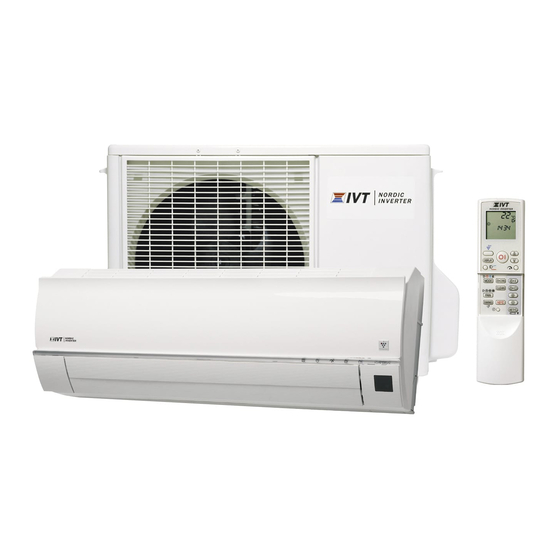
SPLIT TYPE AIR TO AIR HEAT PUMP 12LR-N MODEL 09LR-N In the interests of user-safety (Required by safety regulations in some countries) the set should be restored to its original condition and only parts identical to those specified should be used. -
Page 2: Chapter 1. Specification
12LRN CHAPTER 1. 12LRN SPECIFICATION Service Manual [1] SPECIFICATION 1. 12LR-N MODEL INDOOR UNIT OUTDOOR UNIT ITEMS 12LR-N Rated cooling capacity (Min– Max.) 3.50 (1.40 - 4.00) Rated heating capacity (Min–Max.) 4.20 (1.40 - 6.00) Moisture removal (at cooling) Liters/h Electrical data Phase Rated frequency... - Page 3 12LRN 2. 09LR-N MODEL INDOOR UNIT OUTDOOR UNIT ITEMS 09LR-N Rated cooling capacity (Min– Max.) 2.50(1.40 - 3.00) Rated heating capacity (Min–Max.) 3.20 (1.40 - 5.00) Moisture removal (at cooling) Liters/h Electrical data Phase Rated frequency Rated voltage 220-240 Cool 2.9 (2.0 - 3.9 )
-
Page 4: External Dimension
12LRN [2] EXTERNAL DIMENSION 1. Indoor unit Unit 18.5 INVERTER AIR CONDITIONER 22.0 2. Outdoor unit 37.5 167.5 1 – 3... -
Page 5: Wiring Diagram
12LRN [3] WIRING DIAGRAM 1. Indoor unit 2. Outdoor unit [4] ELECTRICAL PARTS 1. Indoor unit DESCRIPTION MODEL REMARKS Indoor fan motor MLB469 DC motor Transformer – RTRNWA054JBZZ FUSE1 – QFS-GA078JBZZ (250V, 3.15A) 2. Outdoor Unit DESCRIPTION MODEL REMARKS Compressor 5RS102XBE01 DC motor Outdoor fan motor... -
Page 6: Chapter 2. Explamation Of Circuit And Op- Eration Block Diagrams
12LRN CHAPTER 2. 12LRN EXPLAMATION OF CIRCUIT AND OPERATION Service Manual [1] BLOCK DIAGRAMS 1. Indoor unit Rectification circuit AC power DC power supply circuit 3.15A Fuse Fan motor PWM control circuit Indoor fan motor Rotation pulse input circuit Fan motor pulse detect AC clock circuit Remote controller signal reception circuit Wireless remote control operation... - Page 7 12LRN 2. Outdoor unit AC clock circuit protection Pulse amplitube modulation circuit IGBT protection Unit-unit wiring (AC power Smoothing Power factor Filter Power supply circuit circuit and serial signals) converter circuit circuit CPU oscillator circuit 3.15A DC overvoltage detection circuit protection Outdoor fan Outdoor fan drive circuit...
-
Page 8: Microcomputer Control System
12LRN [2] MICROCOMPUTER CONTROL SYSTEM 1. Indoor unit 1.1. Electronic control circuit diagram 2 – 3... - Page 9 12LRN 1.2. Printed wiring board For 9LRN/2LRN model main PWB From display PWB From Plasma Cluster generator From louver motor From thermistor To Terminal board [2] To Terminal board [1] To Terminal board [N] To Eauth Terminal (PDAI-A248JBWZ) From Fan motor For 9LRN/LRN model display PWB To Main PWB CN5 2 –...
- Page 10 12LRN 2. Outdoor unit 2.1. Electronic control circuit diagram 2 – 5...
- Page 11 12LRN 2.2. Printed wiring board 2 – 6...
-
Page 12: Function
12LRN [3] FUNCTION 1. Function 1.1. Restart control 1.5. Indoor unit overheat prevention control Once the compressor stops operating, it will not restart for 180 sec- During heating operation, if the temperature of the indoor unit heat onds to protect the compressor. exchanger exceeds the indoor unit heat exchanger overheat preven- tion temperature (about 45 to 54C) which is determined by the operat- Therefore, if the operating compressor is shut down from the remote... - Page 13 12LRN 1.9. Peak control 1.14. Power ON start If the current flowing in the air to air heat pump exceeds the peak con- If a jumper cable is inserted in the location marked with HAJP on the trol current the operation frequency is decreased until the current indoor unit control printed circuit board (control PCB), connecting the value drops below the peak control current regardless of the frequency power cord to an AC outlet starts the air to air heat pump in either cool-...
- Page 14 12LRN 1.17. Difference of operation in Auto and Manual modes In the Auto mode, the temperature setting is automatically determined based on the outside air temperature. In addition, the air to air heat pump oper- ation differs from the operation in the Manual mode as explained below. 1.17.1 Difference relating to set temperature Auto mode Manual mode...
- Page 15 12LRN 2. Outline of PAM circuit 2.1. PAM (Pulse Amplitude Modulation) The PAM circuit varies the compressor drive voltage and controls the rotation speed of the compressor. The IGBT shown in the block diagram charges the energy (electromotive force) generated by the reactor to the electrolytic capacitor for the inverter by turning ON and OFF.
- Page 16 12LRN 2.2.1 Detailed explanation of PAM drive circuit sequence AC voltage waveform 50Hz 1.2mS Clock 2.6mS 0.25 2.3mS IGBT ON 2.2.2 AC clock (zero-cross) judgment • The clock circuit determines the time from one rising point of the clock waveform to the next rising point. The detected clock waveform is used to judge the power source frequency (50 Hz).
- Page 17 12LRN 2) PAM error indication In case of error “1)” – An error signal is sent to the indoor unit as soon as an error is generated. • Malfunction No. 14-0 is indicated when the error code is called out by the indoor unit's self-diagnosis function. –...
- Page 18 12LRN 3. Explanation of IPM drive circuit The IPM for compressor drive is made by Mitsubishi Electric. The power supply for the IPM drive and the shunt resistance for overcurrent detection, are provided outside the IPM. 3.1. IPM drive power supply circuit The power supply for the upper-phase IGBT (HU, HV, HW) drive employs a bootstrap system, and provides power to the upper-phase IC.
- Page 19 12LRN 3.1.2 DC overcurrent detection circuit When a current of about 20 A or higher flows through the shunt resistance (R49) on the control printed circuit board (PCB), the voltage at this resis- tance is input to IPM CIN pin (15). Then, the gate voltage of the lower-phase IGBT (LU, LV, LW) inside the IPM turns OFF to cut off the overcurrent. At the same time, an L output of more then 20s.
- Page 20 12LRN 4. 120 energizing control (digital position detection control) This control system detects the digital position detection signal and adjusts the rate of acceleration/deceleration accordingly. The motor's induced voltage waveform is input to the comparator in the form of PWM-switched pulse waveform, and a position detection signal is generated as a reference voltage equaling 1/2 of 280 VDC.
-
Page 21: Operation Manual
12LRN [4] OPERATION MANUAL ADJUSTING THE AIR FLOW BASIC OPERATION COANDA AIRFLOW DIRECTION In cool or dry mode, vertical louvre airflow Press the MODE button to select the VERTICAL AIR FLOW DIRECTION is set obliquely upward to deliver cool air operation mode. - Page 22 12LRN 1-HOUR OFF TIMER TIMER OPERATION When the 1-HOUR OFF TIMER is set, the TIMER OFF TIMER ON TO CANCEL unit will automatically turn off after 1 hour. Press the SET/C button. Press the TIMER OFF button. Press the TIMER ON button. The orange TIMER lamp ( ) will turn off.
-
Page 23: Chapter 3. Function And Operation Of Pro- Tective Procedures Protection Device Functions And Operations
12LRN CHAPTER 3. 12LRN FUNCTION AND OPERATION OF PROTECTIVE PROCEDURES Service Manual [1] PROTECTION DEVICE FUNCTIONS AND OPERATIONS Function Operation Self-diagnosis result display Description Detection period Reset condition Indoor Indoor Outdoor unit error unit unit display Operation OFF or ON ✩2 Indoor unit fan lock Operation stops if there is no input When indoor unit fan is... - Page 24 12LRN Function Operation Self-diagnosis result display Description Detection period Reset condition Indoor Indoor Outdoor unit error unit unit display Yes ✩2 10 AC overcurrent error Indoor and outdoor units stop if out- When compressor is in Replacement of defec- in compressor OFF door AC current exceeds about 3 A non-operation tive parts such as IPM...
-
Page 25: Air To Air Heat Pump Operation In Thermistor Error
12LRN Function Operation Self-diagnosis result display Description Detection period Reset condition Indoor Indoor Outdoor unit error unit unit display 29 PAM clock error When power source frequency can- At compressor startup, Compressor continues None not be determined (at startup), or when in operation operation without stop- when power source clock cannot... - Page 26 12LRN 2. Outdoor unit Item Mode Control operation When resistance Short-circuit When resistance Open-circuit is low (tempera- is high (tempera- ture judged higher ture judged lower than actual) than actual) Compressor cham- Cooling Expansion valve Compressor oper- Compressor high Layer short-circuit Outdoor unit ther- ber thermistor Dehumidifying...
-
Page 27: Thermistor Temperature Characteristics
12LRN [3] THERMISTOR TEMPERATURE CHARACTERISTICS 1. Indoor unit thermistor temperature characteristics Figure 1 Temperature properties of indoor thermistors Room temperature Thermistor Signal Color Room temperature Yellow thermistor TH1 (CN8 3 - 4 ) Heat exchange Orange Heat exchange thermistor TH2 (CN8 1 - 2 ) To measure the resistance, first remove the soldering as shown at right. -
Page 28: How To Operate The Outdoor Unit Independently
12LRN [4] HOW TO OPERATE THE OUTDOOR UNIT INDEPENDENTLY 1. Cooling in 40 Hz fixed mode To operate the outdoor unit independently, short-circuit the sections indicated by arrows in the diagram below with an adapter, and apply 220-240 VAC between (1) and (N) on the terminal board of the outdoor unit. This allows the outdoor unit to be operated in cooling mode independently. (Do not operate the outdoor unit in this condition for an extended period of time.) PWB pattern side. - Page 29 12LRN Main cause Inspection method Normal value/condition Remedy Open-circuit or short-circuit in wir- Check if wires of light receiving Wires of light receiving section Replace wires of light receiving ing of light receiving section. section are caught. should not have any damage section.
-
Page 30: Malfunction (Parts) Check Method
12LRN 9. Operation stops after a few minutes and restarts, and this process repeats Main cause Inspection method Normal value/condition Remedy Dried-up electrolytic capacitor. Measure 320VDC line voltage. 300 V or higher. Replace electrolytic capacitor. Layer short-circuit in expansion Measure resistance. 463... - Page 31 12LRN 2. Procedure for determining defective expansion valve Measure resistance in expansion valve coil. Normal resistance between red terminal of expansion valve lead wire and white or orange terminal,gray terminal of expansion valve lead wire and yellow or blue terminal : about 46 (at 20 (red) Checker...
- Page 32 12LRN 5. IPM check method Turn off the power, let the large capacity electrolytic capacitor (C10) discharge completely, and dismount the IPM. Then, using a tester, check leak current between C and E. When using a digital tester, the (+) and (-) tester lead wires in the table must be reversed. Needle-type tester Normal resistance value Needle-type tester...
-
Page 33: Outdoor Unit Check Method
12LRN [7] OUTDOOR UNIT CHECK METHOD After repairing the outdoor unit, conduct the following inspection procedures to make sure that it has been repaired completely. Then, operate the compressor for a final operation check. 1. Checking procedures Item Check method Normal value/condition Remedy Preparation... - Page 34 12LRN 2. Troubleshooting of outdoor unit electric components Check 220-240VAC input voltage. Check 320VDC Short-circuit in DC fan motor Does LED light? between IPM pins Short-circuit in IPM (20) and (24) ? Short-circuit in diode bridge Blown fuse Defective electrolytic capacitor Wire disconnection, PWB pattern damage Short-circuit in PAM IGBT (Q5) Defective switching power supply circuit...
- Page 35 12LRN 3. Caution in checking printed circuit boards (PWB) 3.1. Non-insulated control circuit The GND terminals of the low-voltage circuits (control circuits for microcomputer and thermistors and drive circuits for expansion valve and relays) on the control printed circuit board (PWB) are connected to the compressor drive power supply (320-VDC negative terminal). Therefore, exercise utmost caution to prevent electric shock.
-
Page 36: Troubleshooting Guide
12LRN [8] TROUBLESHOOTING GUIDE 1. Self-Diagnosis Function 1. Indoor unit • To display the self-diagnosis,hold down the AUX button for over 5 seconds on the indoor unit when the indoor unit is not operating. • The operation lamp(red),timer lamp(orange)and Plasmcluster lamp(blue)flash to indicate the information of malfuntion. •... - Page 37 12LRN <INDOOR UNIT> :1-second ON / 1-second OFF Problem Outdoor Indoor unit Malfunc- Content of diagnosis Check point Action symptom unit indi- tion No. cation Lamp Main Sub Main (LED1) Normal con- Normal Timer (Orange) Normal dition blinking...
- Page 38 12LRN Problem Outdoor Indoor unit Malfunc- Content of diagnosis Check point Action symptom unit indi- tion No. cation Lamp Main Sub Main (LED1) Indoor unit 3-time Timer (Orange) Dry opera- Temporary stop (Temporary stop for cycle operates.
- Page 39 12LRN Problem Outdoor Indoor unit Malfunc- Content of diagnosis Check point Action symptom unit indi- tion No. cation Lamp Main Sub Main (LED1) Indoor and 8-time Timer (Orange) Abnormal Abnormal wire (1) Check the expansion (1) Replace the out- outdoor units wire check...
- Page 40 12LRN Problem Outdoor Indoor unit Malfunc- Content of diagnosis Check point Action symptom unit indi- tion No. cation Lamp Main Sub Main (LED1) Indoor and 11-time Timer (Orange) Outdoor unit Outdoor unit DC (1) Check connector (1) Correct the instal- outdoor units DC fan...
- Page 41 12LRN Problem Outdoor Indoor unit Malfunc- Content of diagnosis Check point Action symptom unit indi- tion No. cation Lamp Main Sub Main (LED1) Indoor and 13-time Timer (Orange) DC com- Compressor (1) Check the colors (1) Correct the instal- outdoor units pressor...
- Page 42 12LRN Problem Outdoor Indoor unit Malfunc- Content of diagnosis Check point Action symptom unit indi- tion No. cation Lamp Main Sub Main (LED1) Indoor unit Lighting Timer (Orange) Wiring Serial short-cir- (1) Check the wiring (1) Correct the wiring.
- Page 43 12LRN Malfunction indications due to erroneous wiring during air conditioner installation Inter-unit wiring error mode Symptom Malfunction diagnosis display “18-1” Indoor Outdoor unit unit Malfunction diagnosis display None (Displays “18-0” when malfunction code is called out.) Indoor Outdoor unit unit Malfunction diagnosis display None (Displays “18-0”...
-
Page 44: Flow Fow Refrigerant
12LRN CHAPTER 4. 12LRN REFRIGERATION CYCLE Service Manual [1] FLOW FOW REFRIGERANT Indoor unit Evaporator Flare coupling Flare coupling 3-way 2-way valve valve Heating Cooling Silencer Strainer Outdoor unit Accumulator Antifreeze pipe Expansion Silencer valve Comp- ressor Coil Reverse valve Condenser [2] STANDARD CONDITION Indoor side... -
Page 45: Performance Curves
12LRN [4] PERFORMANCE CURVES NOTE 1) Indoor fan speed: Hi 2) Vertical adjustment louver “45”, Horizontal adjustment louver “front” 3) Indoor air temp.: Cooling 27C, Heating 20C 4) Power source: 230V, 50Hz 5) Performance corresponding to change in outside temperature when compressor is fixed to rated operation. 1. -
Page 46: Chapter 5. Disassembly Procedure
12LRN CHAPTER 5. 12LRN DISASSEMBLY PROCEDURE Service Manual Be sure to disconnect the power cord from the AC power outlet before starting the disassembly procedure. Be sure to install screws to their original positions after repairing After the air conditioner is repaired or parts are replaced, measure insulation resistance of the equipment using an insulation resistance meter. If the measured resistance is lower than 1 MΩ,inspect parts and repair or replace defective parts. - Page 47 12LRN 7) Remove the grill (Unhook the 3 hooks shown in the picture.) 11)Cut the fixing band and remove the thermistor and earth wire. fixin g band 12)Remove the screw fixing the control box cover. 8) Remove the 2 screws fixing the front panel R and front panel L. 13)Remove the 3 connectors.(FAN MOTOR, LOUVER MOTOR and PLASMCLUSTER) 9) Remove the front panel R.
- Page 48 12LRN 15)Unhook the 2 hooks and remove the filter guide C. 17)Unhook of the motor cover. Support the motor with your hand when unhooking the motor cover. filter guide C 18)Slide the Cross-flow fan motor to the right and remove it. 19)Remove the pipe holder.
-
Page 49: The Wire Guard And The Plasm- Cluster Unit
12LRN [2] THE WIRE GUARD AND THE PLASM- 3) Rotate the guard holder L in clockwise and remove. CLUSTER UNIT 1) Remove the 2 screws fixing the guard holder L and guard holder R. (left side) (right side) 2) Pull the left side of wire guard forward, and the hook of the guard holder L will be unhooked. - Page 50 12LRN 5) Pull the right side of the wire guard R, and unhook the guard holder 8) Remove the 2 screw covers. ・Insert the (-) screwdriver in the 2 holes. 6) Rotate the guard holder R in anticlockwise and remove. 9) Unscrew the 2 screws.
-
Page 51: Outdoor Unit
12LRN [3] OUTDOOR UNIT 4) Unscrew the screw on the right side of the front panel. 1) Unscrew the screw and remove the control box cover. 5) Unscrew the screw on the left side of the front panel. 2) Unscrew the 2 screws on the right side of the top plate. 6) Unscrew the 4 screws on the front panel, and remove front panel. - Page 52 12LRN 8) Unscrew the 3 screws on the back side of the side cover R, and 12) Remove the 2 screws fixed the bulkhead plate. remove the side cover R. 9) Unscrew the 3 screws on the side cover L, and remove the side cover L.
- Page 53 12LRN 15) Remove the lead wire, the thermistor, and the cover gasket. 19)Unscrew the 2 screws and remove the motor angle. 20) *Thermistor position. 16)Remove the compressor cover. Black Yellow 17)Remove the 5 thermistors. * Orange 18)Remove the outdoor fan. Green 5 –...
- Page 54 12LRN 5 – 9...
-
Page 55: Parts Guide
SPLIT TYPE AIR TO AIR HEAT PUMP 12LR-N MODEL 09LR-N In the interests of user-safety (Required by safety regulations in some countries) the set should be restored to its original condition and only parts identical to those specified should be used. - Page 56 12LRN [1] INDOOR UNIT PARTS 1-47 1-45 1-33 1-41 1-37 1-40 9-11 1-43 1-30 1-42 1-34 1-31 5-15 1-10 1-12 1-44 1-54 1-18 1-32 1-11 1-35 5-12 5-10 5-12 1-15 1-17 5-11 1-46 1-19 1-26 1-13 1-28 1-14 1-13-1 1-29 1-24 1-48 1-16...
- Page 57 12LRN PARTS CODE P R I C E N E W P A R T DESCRIPTION RANK MARK RANK [1] INDOOR UNIT PARTS 1-30 FRONT PANEL R GWAK-A374JBFA 1-31 DISPLAY PANEL HDECQA345JBEA 1-32 COVER PCOV-B738JBEZ 1-33 CABINET ASS'Y DCHS-A724JBKZ 1-34 COVER PCOV-B700JBFZ 1-35...
- Page 58 VHVTNR9V511-A+ 6-2-5 LEAD WIRE (ON DISPLAY BOARD UNIT) QW-VZG320JBZZ WIRING DIAGRAM TLABCC768JBRZ 9-13 TLAB-E917JBEZ EU-ENERGY LABEL (12LR-N) 9-13 TLAB-E922JBEZ EU-ENERGY LABEL (09LR-N) 9-14 NAME LABEL (12LR-N) TSPC-G869JBRA 9-14 NAME LABEL (09LR-N) TSPC-G881JBRA [4] INDOOR PACKING PARTS PRICE PART PARTS CODE...
- Page 59 12LRN [5] OUTDOOR UNIT PARTS 2-34 2-17 2-60 2-48-1 2-46-2 2-57 2-48-2 2-46-1 2-26 2-7-1 2-7-4 2-7-2 2-60-1 2-46-3 2-33 2-25 2-7-5 2-39-3 2-31 2-37 2-7-3 2-20 2-7-6 1-2-6 2-19 1-2-7 2-56 3-12 2-18 1-2-8 1-10 2-10 2-39-7 2-38 2-21 2-11 2-13 1-11...
- Page 60 COMP COVER TOP B PSPF-B205JBEZ 2-28 COMPRESSOR COVER PSPF-B005JBEZ 2-28 COMPRESSOR COVER PSPF-B203JBEZ 2-31 SUB LABEL TLAB-D433JBRZ 2-32 IVT LABEL TLABBA286JBRA 2-33 NAME LABEL[09LR-N] TSPC-G882JBRZ 2-33 NAME LABEL[12LR-N] TSPC-G870JBRZ 2-34 SIDE COVER L PPLT-A606JBTA 2-35 SEAL PSEL-E206JBEZ 2-37 COVER PCOV-A997JBWZ 2-38...
- Page 61 [7] OUTDOOR PACKING PARTS 90-1 90-3 i d e 90-2 PRICE PART PARTS CODE DESCRIPTION RANK MARK RANK [7] OUTDOOR PACKING PARTS 90-1 TOP PAD ASS'Y CPADBA048JBKZ 90-2 BOTTOM PAD ASS'Y CPADBA049JBKZ 90-3 PACKING CASE [09LR-N] SPAKCC914JBEZ 90-3 PACKING CASE [12LR-N] SPAKCC902JBEZ...
- Page 62 12LRN INDEX PRICE PART PRICE PART PARTS CODE PARTS CODE RANK MARK RANK RANK MARK RANK MARMPA070JBFA 1-1-20 [ C ] MJNTPA166JBFA 1-1-21 CCAB-A542JBKZ 5-2-2 MLOV-A553JBFA 1-1-22 CCHS-A931JBTA 5-3-1 MLOV-A554JBFA 1-1-23 CCHS-B127JBKZ 5-3-0 MSPR-A026JBE0 5-2-24 CCIL-A142JBKZ 5-3-8 MSPR-A036JBE0 5-2-23 CCYC-C673JBKZ 1-6-1 MSPR-A195JBEZ 5-2-21...
- Page 63 12LRN PRICE PART PARTS CODE RANK MARK RANK PSEL-E209JBEZ 1-1-35 PSEL-E211JBEZ 5-2-60 PSEL-E212JBEZ 5-2-60-1 PSEL-E213JBEZ 5-2-46-2 PSEL-E214JBEZ 5-2-59-1 PSEL-E215JBEZ 5-2-14-1 PSEN-A070JBKZ 3-6-2-2 PSEN-A071JBKZ 3-6-2-1 PSHE-A321JBEZ 1-1-54 PSKR-A284JBPZ 5-2-14 PSPF-B004JBEZ 5-2-27 PSPF-B005JBEZ 5-2-28 PSPF-B203JBEZ 5-2-28 PSPF-B204JBEZ 5-2-27 PSPF-B205JBEZ 5-2-27-1 PSPF-B206JBEZ 5-3-20 PSPF-B212JBEZ 5-3-21 PSRN-A091JBEZ...
- Page 64 © COPYRIGHT XXXX BYSHARP CORPORATION ALL RIGHTS RESERVED. No part of this publication may be reproduced, stored in a retrieval system, or transmitted in any form or by any means, electronic, mechanical, photocopying, recording, or otherwise, without prior written permission of the publisher.