Table of Contents
Advertisement
E 2006 Lennox Industries Inc.
Dallas, Texas, USA
RETAIN THESE INSTRUCTIONS
FOR FUTURE REFERENCE
Do not store or use gasoline or other
flammable vapors and liquids in the
vicinity of this or any other ap-
pliance.
Installation and service must be
performed by a qualified installer,
service agency or the gas supplier.
06/09
*2P0609*
INSTALLATION
INSTRUCTIONS
G61MPVT SERIES UNITS
GAS UNITS
505,187M
06/2009
Table of Contents
WARNING
FIRE OR EXPLOSION HAZARD.
Failure to follow safety warnings exact-
ly could result in serious injury, death,
or property damage.
WHAT TO DO IF YOU SMELL GAS:
D Do not try to light any appliance.
D Do not touch any electrical switch; do not
use any phone in your building.
D Leave the building immediately.
D Immediately call your gas supplier from a
neighbor's phone. Follow the gas supplier's
instructions.
D If you cannot reach your gas supplier, call
the fire department.
Page 1
. . . . . . . . . . . . . . . . . . . . . . . . . . . . . . .
. . . . . . . . . . . . . . . . . . . . . . .
. . . . . . . . . . . . . . . . . . . . . . . . . . . . . .
. . . . . . . . . . . . . . . . . . . . . . . . . . . . . . . . . . . . . . . . .
. . . . . . . . . . . . . . . . . . . . . . . . . . . . . . . . . . .
. . . . . . . . . . . . . . . . . . .
. . . . . . . . . . . . . . . . . . . . . . . . .
. . . . . . . . . . . . . . . . . . . . .
. . . . . . . . . . . . . . . . . . . . . . . . . . . . . .
. . . . . . . . . . . . . . . . . . . . . . . . . . . . . . . . . . .
. . . . . . . . . . . . . . . . . . . . . . . . . . . . . . . . . . . . .
. . . . . . . . . . . . . . . . . . . . . . .
. . . . . . . . . . . . . . . . . . . . . . . . . . . . . . . . . .
. . . . . . . . . . . . . . . . . . . . . .
. . . . . . . . . . . . . . . . . . . . . . . .
. . . . . . . . . . . . . . . . . . . . . . . . . . . . . . . . . . . . . .
. . . . . . . . . . . . . . . . . . . . . . . . . . . . . . . . .
. . . . . . . . . . . . . . . . . . . . . . . . . . . . . . . . . . . . . .
. . . . . . . . . . . . . . . . . . . . . . . . . . . . . . .
. . . . . . . . . . . . . . . . . . . . . . . . . . . . . .
. . . . . . . . . . . . . . . . . . . .
*P505187M*
Litho U.S.A.
2
. . . . . . . . . . . . . . . . . . .
3
4
4
. . . . . . . . . . . . . . . . . .
5
9
9
10
11
12
13
21
23
27
34
35
. . . .
35
36
. . . . . . . . . . . . . . . . .
37
38
40
40
. . . . . . . . . . . .
41
. . . . . . . . .
44
45
51
51
. . . . . . . . . . . . . .
52
505,187M
Advertisement
Table of Contents

Related Manuals for Lennox G61MPVT-36B-070


Summary of Contents for Lennox G61MPVT-36B-070
-
Page 1: Table Of Contents
INSTALLATION INSTRUCTIONS E 2006 Lennox Industries Inc. Dallas, Texas, USA G61MPVT SERIES UNITS GAS UNITS 505,187M 06/2009 Litho U.S.A. Table of Contents Unit Dimensions ....... -
Page 2: Unit Dimensions
G61MPVT Unit Dimensions − mm *60C and 60D size units installed in upflow applications that require air volumes over 1800 cfm (850 L/s) must have one of the following: 1. Single side return air with transition, to accommodate SUPPLY AIR 20 x 25 x 1 in. -
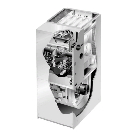
Page 3: G61Mpvt Parts Arrangement
G61MPVT Parts Arrangement TOP CAP DuralokPlus HEAT EXCHANGER ASSEMBLY CABINET BURNER BOX ASSEMBLY GAS VALVE AND MANIFOLD FLUE COLLAR COMBUSTION AIR PRESSURE WARM HEADER PROVE SWITCHES (COLLECTOR) COMBUSTION AIR INDUCER CONDENSER COIL BURNER PRIMARY LIMIT ACCESS PANEL COLD HEADER (COLLECTOR) BLOWER ACCESS PANEL... -
Page 4: Shipping And Packing List
G61MPVT Gas Furnace Shipping and Packing List Package 1 of 1 contains The G61MPVT gas furnace is equipped with a two−stage, 1 − Assembled G61MPVT unit variable speed integrated control. This control ensures 1 − Bag assembly containing the following: compatibility with a thermostat which provides humidity 3 −... -
Page 5: Installation − Setting Equipment
Upflow Applications Installation − Setting Equipment The G61MPVT gas furnace can be installed as shipped WARNING in the upflow position. Refer to figure 3 for clearances. Installation Clearances Do not install the furnace on its front or its back. Do not connect the return air ducts to the back of the fur- nace. - Page 6 Horizontal Applications 5 − Return air from bottom and one side. Refer to Engineering Handbook for additional information. G61MPVT furnaces, with exception G61MPVT applications which include side return air G61MPVT−60D−135, can be installed in horizontal applica- and a condensate trap installed on the same side of the tions with either right−...
- Page 7 TYPICAL HORIZONTAL ROOF SPACE INSTALLATION (FORCED AIR FURNACE) EXHAUST PIPE INTAKE PIPE CONNECTOR NOTE − Condensate trap and condensate line must be protected by self−regulating heating cable and insulation when run through unconditioned spaces. RAISED PLATFORM SERVICE PLATFORM CONDENSATE LINE FIGURE 7 Platform Installation of Horizontal Unit in Roof Space 1 −...
- Page 8 Return Air −− Horizontal Applications 3 − Set the unit over the plenum and seal the plenum to the unit. Return air may be brought in only through the end of a fur- 4 − Ensure that the seal is adequate. nace installed in the horizontal position.
-
Page 9: Filters
PLENUM (Field Provided) G61MPVT UNIT SEALING STRIP (Field Provided) SUPPLY AIR PLENUM É É É É CABINET SIDE PANEL SECURE FROM PROPERLY INSIDE CABINET SIZED FLOOR Side View ADDITIVE BASE OPENING FIGURE 12 Filters This unit is not equipped with a filter or rack. A field−pro- vided filter is required for the unit to operate properly. -
Page 10: Pipe & Fittings Specifications
Class 12 / Schedule 40 or equivalent as vent pipe equivalencies which must be used when sizing All pipe, fittings, primer and solvent cement must conform vent pipe. All Lennox vent terminations are PVC or ABS. TABLE 4 OUTDOOR TERMINATION KITS AND CORRESPONDING EQUIVALENCIES... -
Page 11: Vent Piping Guidelines
Size pipe according to tables 5 and 6. Table 5 lists the mini- ent sizes of vent pipe, a combination vent pipe may be mum equivalent vent pipe lengths permitted. Table 6 lists used. Contact Lennox for assistance in sizing vent pipe in the maximum equivalent pipe lengths permitted. these applications. -
Page 12: Joint Cementing Procedure
Use the following steps to correctly size vent pipe diameter. IMPORTANT Refer to Vent Pipe Size Determination Worksheet on page 52. The G61MPVT unit is not suitable for use at eleva- 1 − Determine the vent termination and its corresponding tions over 610m. -
Page 13: Venting Practices
downflow positions. Exhaust piping exits from the top Venting Practices of the unit in horizontal air discharge applications. Glue the field−provided exhaust vent pipe (or provided 1 − Use recommended piping materials for exhaust piping street ell or reducing ell in upflow or downflow applica- (Class E / Class 12 / Schedule 40). - Page 14 TYPICAL EXHAUST PIPE CONNECTIONS AND CONDENSATE TRAP INSTALLATION IN UPFLOW OR DOWNFLOW DIRECT OR NON−DIRECT VENT APPLICATIONS (Right−Hand Exit in Upflow Application Shown) 80mm 50mm PLUG PLUG G61MPVT−070 TRANSITION or 090 with 80mm vent pipe 50mm 50mm 50mm 50mm VENT PLUG (Must be glued in place)
- Page 15 TYPICAL AIR INTAKE PIPE CONNECTIONS UPFLOW OR DOWNFLOW DIRECT VENT APPLICATIONS (Right−Hand Exit in Upflow Application Shown) 80mm TRANSITION 50mm 80mm 50mm* TRANSITION 50mm 50mm* 50mm* PLUG (Must be 50mm 50mm glued in place) G61MPVT−36B−070 G61MPVT−36B−070 G61MPVT−36B−070 G61MPVT−60C−090 G61MPVT−60C−090 G61MPVT−60C−090 G61MPVT−60C−110* G61MPVT−60C−110* G61MPVT−60D−135*...
- Page 16 TYPICAL AIR INTAKE PIPE CONNECTIONS DOWNFLOW NON−DIRECT VENT APPLICATIONS (Right−Hand Exit in Downflow Applications Shown) 50mm SWEEP INTAKE DEBRIS SCREEN (Provided) 150mm Max. PLUG PLUG (Must be glued in (Must be place) glued in place) 50mm 438mm INTAKE DEBRIS SCREEN 50mm SWEEP ELL (Provided) Downflow Additive Flloor Base...
- Page 17 General Guidelines for Vent Terminations for Non-Direct cable may be installed on exhaust piping and termination to Vent Installations. prevent freeze−ups. Heating cable installation kit is avail- In Non-Direct Vent applications, combustion air is taken able from Lennox. Page 17...
-
Page 18: Vent Termination Clearances
VENT TERMINATION CLEARANCES (AS 5601) − G61MPVT VENT TERMINATION − AIR INLET OF OTHER APPLIANCE less than 10 ft (3.048M) A − Clearance above ground level − 305mm. E − Clearance to non−mechanical air supply inlet or outlet − 300mm minimum horizontal and 1000mm minimum verti- B −... - Page 19 7 − On field supplied terminations, a minimum separation distance between the end of the exhaust pipe and the INTAKE end of the intake pipe is 203mm (8 inches). TERMINATION EXHAUST TABLE 7 EXHAUST TERMINATION EXHAUST PIPE TERMINATION SIZE REDUCTION G61MPVT Exhaust Pipe Size Termination Pipe Size...
- Page 20 Condensate Piping 3 − Glue the field−provided coupling or pipe to the trap. Install a tee and vent pipe near the trap. This unit is designed for either right- or left-side exit of con- densate piping in either upflow or downflow applications; NOTE −...
-
Page 21: Gas Piping
Gas Piping MANUAL MAIN SHUT−OFF FURNACE VALVE WILL NOT HOLD CAUTION NORMAL TEST PRESSURE ISOLATE DO NOT over−tighten when attaching pipe or fittings GAS VALVE to gas valve. Damage may occur. 1 − Gas piping may be routed into the unit through either the left- or right-hand side. - Page 22 Horizontal Applications Possible Gas Piping Configerations MANUAL MAIN SHUT−OFF Horizontal Application VALVE Left−Side Air Discharge MANUAL MAIN SHUT−OFF VALVE GROUND JOINT UNION GROUND JOINT DRIP LEG UNION DRIP LEG Horizontal Application MANUAL Right−Side Air Discharge MAIN SHUT−OFF VALVE GROUND JOINT UNION DRIP LEG FIGURE 30...
-
Page 23: Electrical
5 − Electrically ground the unit according to local codes. Electrical NOTE − The G61MPVT furnace contains electronic ELECTROSTATIC DISCHARGE (ESD) components that are polarity sensitive. Make sure that Precautions and Procedures the furnace is wired correctly and is properly grounded. CAUTION 6 −... - Page 24 TYPICAL G61MPVT FIELD WIRING DIAGRAM USE COPPER CONDUCTORS ONLY. FIELD INSTALLED CLASS II 24V FIELD INSTALLED LINE VOLTAGE FIGURE 31 Page 24...
- Page 25 TABLE 9 Field Wiring Applications Jumper Settings (See figure 33) W915 Heat Staging Two−Stage W914 Dehu- W951 Thermostat Wiring Connections Jumper Cooling midification Heat Pumps 1Heat / 1 Cool 15 Minutes Intact Intact Intact CONTROL OUTDOOR T’STAT TERM. STRIP UNIT NOTE −...
- Page 26 TYPICAL G61MPVT WIRING DIAGRAM FIGURE 32 Page 26...
-
Page 27: Integrated Control Board
Integrated Control Board TWO−STAGE, VARIABLE SPEED INTEGRATED CONTROL BOARD HEAT STAGING DELAY JUMPER BLOWER OPERATION SWITCHES BLOWER DIAGNOSTIC DELAY JUMPER OPERATIONAL LEDS FIGURE 33 G61MPVT units are equipped with a two−stage, variable provide either a 10−minute or a 15−minute delay before sec- speed integrated control. - Page 28 On−Board Jumper W914 TABLE 11 Cooling Mode Blower Speeds On−board jumper W914, which connects terminals DS and Speed Switch 3 Switch 4 R on the integrated control board, must be cut when the fur- 1 − Low nace is installed with a thermostat which features humidity control.
- Page 29 Switches 7 and 8 −− Heating Mode Blower Speed −− 100% CFM 100% CFM Switches 7 and 8 are used to select heating mode blower 45 SEC. DEMAND motor speed. The unit is shipped from the factory with the dip switches positioned for medium low (2) speed indoor blower motor operation during the heating mode.
- Page 30 TABLE 15 G61MPVT−60C−090 BLOWER MOTOR PERFORMANCE (LESS FILTER) 0.0" to 0.8" w.g. (0 through 200 Pa) External Static Pressure Range Factory Settings: Heating Speed − 2; Cooling Speed − 4; Speed Adjust − NORM. Return Air Options: Bottom; both sides; or bottom and one side. Speed Switch Positions ADJUST"...
- Page 31 TABLE 17 G61MPVT−60C−090 BLOWER MOTOR PERFORMANCE (LESS FILTER) 0.0" to 0.8" w.g. (0 through 200 Pa) External Static Pressure Range Factory Settings: Heating Speed − 2; Cooling Speed − 4; Speed Adjust − NORM. Return Air Options: Single side return with optional RAB return air base Speed Switch Positions ADJUST"...
- Page 32 TABLE 19 G61MPVT−60C−110 BLOWER MOTOR PERFORMANCE (LESS FILTER) 0.0" to 0.8" w.g. (0 through 200 Pa) External Static Pressure Range Factory Settings: Heating Speed − 2; Cooling Speed − 4; Speed Adjust − NORM. Return Air Options: Single side return air − Bold volumes require field−fabricated transition to accommodate 20 x 25 x 1 in.
- Page 33 TABLE 21 G61MPVT−60D−135 BLOWER MOTOR PERFORMANCE (LESS FILTER) 0.0" to 0.8" w.g. (0 through 200 Pa) External Static Pressure Range Factory Settings: Heating Speed − 2; Cooling Speed − 4; Speed Adjust − NORM. Return Air Options: Bottom. Speed Switch Positions ADJUST"...
-
Page 34: Unit Start−Up
The gas valve on the G61MPVT is equipped with a gas Unit Start−Up control knob. Use only your hand to turn the gas control FOR YOUR SAFETY READ BEFORE OPERATING knob. Never use tools. If the knob will not push in or turn by hand, do not try to repair it. -
Page 35: Gas Pressure Adjustment
NOTE − Pressure test adapter kit (10L34) is available from Turning Off Gas to Unit Lennox to facilitate manifold pressure measurement. 1 − Set the thermostat to the lowest setting. 1 − Connect test gauge to outlet tap on gas valve. -
Page 36: Other Unit Adjustments
TABLE 23 Conversion Kit Requirements for Models −070, −090, −110 and −135 High Altitude Pressure Switch Kit LPG/Propane Kit LPG/Propane to ORDER TWO EACH Natural Gas Kit Input 611 − 1372 m 0 − 610 m 611 − 1372 m 0 −... -
Page 37: Heating Sequence Of Operation
5 − Is the filter dirty or plugged? Dirty or plugged filters will 8 − When the thermostat demand for low−fire (first stage) heat is satisfied, the gas valve is de−energized and the cause the limit control to shut the unit off. field−selected indoor blower off delay begins. -
Page 38: Service
3 − Mark all gas valve wires and disconnect them from Service valve. 4 − Remove gas supply line connected to gas valve. Re- move gas valve/manifold assembly. WARNING 5 − Remove sensor wire from sensor. Disconnect 2-pin plug from the ignitor. ELECTRICAL SHOCK, FIRE, OR EXPLOSION HAZARD. - Page 39 20 − Back wash heat exchanger with soapy water solution 39 − Reinstall gas valve manifold assembly. Reconnect or steam. If steam is used it must be below 135°C gas supply line to gas valve. (275°F). 40 − Reinstall burner box cover. 21 −...
-
Page 40: Requirements
Lennox does not recommend the use of G61MPVT units as Requirements a construction heater during any phase of construction. Very low return air temperatures, harmful vapors and op- Use only the type of gas approved for use with this furnace. -
Page 41: Combustion, Dilution & Ventilation Air
Z223.1/NFPA 54). This reprinted material is not the com- supervisor. plete and official position of the ANSI on the referenced Lennox Industries Inc. subject, which is represented only by the standard in its P.O. Box 799900 entirety. - Page 42 Unconfined Space of total input rating of all gas−fired equipment in the con- fined space. Each opening must be at least 64516 mm An unconfined space is an area such as a basement or (100 square inches). One opening shall be within 305 mm large equipment room with a volume greater than 1.42 m (12 inches) of the top of the enclosure and one opening per .29 kW (50 cubic feet per 1,000Btu) per hour of the...
- Page 43 When ducts are used, they shall be of the same cross−sec- EQUIPMENT IN CONFINED SPACE − ALL AIR FROM OUTSIDE tional area as the free area of the openings to which they (All Air Through Ventilated Attic) connect. The minimum dimension of rectangular air ducts shall be no less than 75mm (3 inches).
-
Page 44: Ignition Control Board Diagnostic Codes
Ignition Control Board Diagnostic Codes (Red LED) FLASH CODE STATUS / ERROR DESCRIPTION (X + Y) FLASH CODE DESCRIPTIONS Pulse A 1/4 second flash followed by four seconds of off time. Heartbeat Constant 1/2 second bright and 1/2 second dim cycles. LED flashes X times at 2Hz, remains off for two seconds, flashes Y times at 2Hz, remains off for four X + Y seconds, then repeats. -
Page 45: Troubleshooting
Troubleshooting: Heating Sequence of Operation HEATING SEQUENCE OF OPERATION NORMAL AND ABNORMAL HEATING MODE POWER ON GAS VALVE OFF. COMBUSTION AIR INDUCER OFF. INDOOR BLOWER OFF. (RESET CONTROL BY CONTROL SELF−CHECK OKAY? TURNING MAIN POWER OFF.) POLARITY REVERSED. STATUS ERROR CODE 5 + 4. POLARITY OKAY? IS THERE A SIGNAL HOLDS UNTIL UNIT IS PROPERLY GROUNDED. - Page 46 Troubleshooting: Heating Sequence of Operation (Continued) HEATING SEQUENCE OF OPERATION CONTINUED THERMOSTAT CALLS FOR HEAT STATUS LED − HEARTBEAT (Refer to box A on previous page) FIRST−STAGE (LOW FIRE) PRESSURE GAS VALVE OFF. COMBUSTION AIR INDUCER SWITCH CLOSED WITHIN 2.5 MINUTES? OFF.
- Page 47 Troubleshooting: Heating Sequence of Operation (Continued) HEATING SEQUENCE OF OPERATION CONTINUED THERMOSTAT CALLS FOR HEAT. STATUS LED −− HEARTBEAT. SEE BOX A. FLAME SIGNAL ABOVE (u1.40 microamps) LOW FLAME SIGNAL (Does not affect control operation) STATUS ERROR CODE 1 + 2. SINGLE−STAGE THERMOSTAT MODE TWO STAGE THERMOSTAT MODE (Heat staging jumper on 10 or 15 minutes)
- Page 48 Troubleshooting: Heating Sequence of Operation (Continued) HEATING SEQUENCE OF OPERATION CONTINUED SEE BOX A NORMAL OPERATION. SEE BOX B THERMOSTAT CALLS FOR HEAT. RETURN TO FIRST−STAGE HEAT MODE. FIRST−STAGE CONTINUES UNTIL SECOND− STAGE PRESSURE SWITCH CAN BE PROVEN SECOND−STAGE (HIGH FIRE) HEAT or HEAT DEMAND IS SATISFIED.
- Page 49 Troubleshooting: Cooling Sequence of Operation COOLING SEQUENCE OF OPERATION POWER ON SIGNAL POLARITY REVERSED. CONTROL WILL CONTINUE TO CALL FOR COOLING IS POLARITY REVERSED? IN THIS CONDITION. STATUS ERROR CODE 5 + 4. SIGNAL IMPROPER GROUND AT LED. CONTROL WILL CONTINUE TO CALL FOR COOLING IS THERE IN THIS CONDITION.
- Page 50 Troubleshooting: Continuous Fan Sequence of Operation CONTINUOUS LOW SPEED FAN SEQUENCE OF OPERATION MANUAL FAN SELECTION MADE AT THERMOSTAT. AFTER 2 SECOND DELAY, INDOOR BLOWER IS ENERGIZED ON CONTINUOUS FAN SPEED. THERMOSTAT CALLS FOR FIRST STAGE COOL. THERMOSTAT CALLS FOR FIRST−STAGE HEAT. INDOOR BLOWER RAMPS TO FIRST STAGE AFTER 45−SECOND DELAY, INDOOR BLOWER COOLING SPEED AFTER A 2−SECOND DELAY.
-
Page 51: Repair Parts List
Repair Parts List The following repair parts are available through Lennox dealers. When ordering parts, include the complete furnace model number listed on the nameplate −− Example: G61MPVT−36B−070−01. Cabinet Parts Heating Parts Upper access panel Flame Sensor Blower access panel... -
Page 52: Start−Up & Performance Check List
G61MPVT Start−Up & Performance Check List Job Name Job No. Date Job Location City State Installer City State Technician Unit Model No. Serial No. Heating Section Electrical Connections Tight? Blower Motor H.P. Supply Voltage Gas Piping Connections Blower Motor Amps Tight &...