Lennox G60UHV?36A?070 Installation Instructions Manual
G60uhv(x) series gas furnace
Hide thumbs
Also See for G60UHV?36A?070:
- Brochure & specs (6 pages) ,
- Installation instructions manual (50 pages)
Table of Contents
Advertisement
E 2008 Lennox Industries Inc.
Dallas, Texas, USA
RETAIN THESE INSTRUCTIONS
FOR FUTURE REFERENCE
Do not store or use gasoline or other
flammable vapors and liquids in the
vicinity of this or any other ap-
pliance.
Installation and service must be
performed by a qualified installer,
service agency or the gas supplier.
10/08
*2P1008*
INSTALLATION
INSTRUCTIONS
G60UHV(X) Series
GAS FURNACE
506177−01
10/2008
Supersedes 505,121M
Table of Contents
WARNING
FIRE OR EXPLOSION HAZARD.
Failure to follow safety warnings exact-
ly could result in serious injury, death,
or property damage.
WHAT TO DO IF YOU SMELL GAS:
D Do not try to light any appliance.
D Do not touch any electrical switch; do not
use any phone in your building.
D Leave the building immediately.
D Immediately call your gas supplier from a
neighbor's phone. Follow the gas supplier's
instructions.
D If you cannot reach your gas supplier, call
the fire department.
Page 1
. . . . . . . . . . . . . . . . . . . . . . . . . . . . . . . .
. . . . . . . . . . . . . . . . . . . . . . . .
. . . . . . . . . . . . . . . . . . . . . . . .
. . . . . . . . . . . . . . . . . . . . . . . . . . . . . . .
. . . . . . . . . . . . . . . . . . . . . . . . . . . . . . . . . . . . . . . .
. . . . . . . . . . . . . . . . . . . . . . . . . . . . . . .
. . . . . . . . . . . . . . . . . . . . . . . . . . . . . . . . . . . . . . . . . .
. . . . . . . . . . . . . . . . . . . . . . . . . . . . . . . . . . . .
. . . . . . . . . . . . . . . . . . . . . . . . . . . . . . . . . . . . . . . .
. . . . . . . . . . . . . . . . . . . . . . . . . . . . . . . . . . . . .
. . . . . . . . . . . . . . . . . . . . . . . . . . . . . . . . . . . . . . .
. . . . . . . . . . . . . . . . . . . . . . .
. . . . . . . . . . . . . . . . . . . . . . . . . . . . . . . . . . .
. . . . . . . . . . . . . . . . . . . . . . . .
. . . . . . . . . . . . . . . . . . . . . . . . .
. . . . . . . . . . . . . . . . . . . . . . . . . .
. . . . . . . . . . . . . . . . . . . . . . . . . . . . . . . . . . . . . . . .
. . . . . . . . . . . . . . . . . . . . . . . . . . . . . . . .
. . . . . . . . . . . . . . . . . . . . . . . . . . . . . . . .
. . . . . . . . . . . . . . . . . . . . . . . . . . . . . . . . .
*P506177-01*
Litho U.S.A.
2
. . . . . . . . . . . . . . . . . . .
3
4
4
4
5
. . . . . . . . . . . . . .
6
9
13
13
13
21
22
28
37
38
38
38
. . . . . . . . . . . . . . . . . . .
39
40
42
42
. . . . . . . . . . . . . . .
43
44
. . . . . . . . . . . . . . . .
50
506177−01
Advertisement
Table of Contents
Troubleshooting

Related Manuals for Lennox G60UHV?36A?070


Summary of Contents for Lennox G60UHV?36A?070
-
Page 1: Table Of Contents
INSTALLATION INSTRUCTIONS E 2008 Lennox Industries Inc. Dallas, Texas, USA G60UHV(X) Series GAS FURNACE 506177−01 10/2008 Supersedes 505,121M Litho U.S.A. Table of Contents Unit Dimensions ....... . -
Page 2: Unit Dimensions
G60UHV(X) Unit Dimensions − inches (mm) 3−3/4 (95) *NOTE − 60C and 60D units that require air volumes over 1800 cfm (850 L/s) must have one of the following: 1. Return air from single side with transition which will accommodate 20 x 25 x 1 in. (508 x 635 x 25 mm) cleanable air filter. -
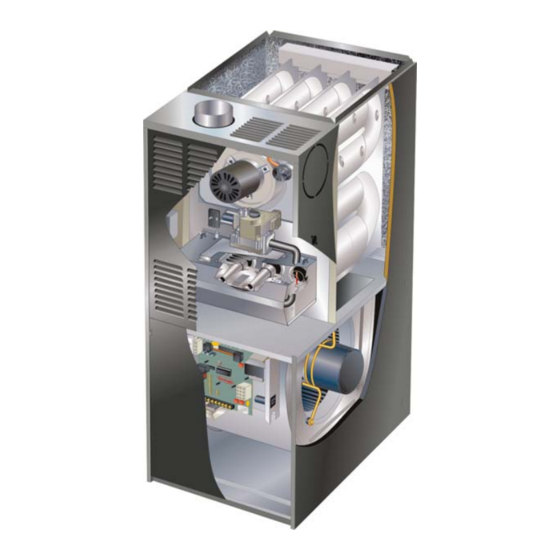
Page 3: G60Uhv(X) Parts Arrangement
G60UHV(X) Parts Arrangement Air Deflector Flue Box Gasket G60UH−60C−110 Gasket Units Only Flue Collector Heat Exchanger Flue Transition Combustion Air Orifice Combustion Air Pressure Switch Assembly (two switches) Combustion Air Inducer Limit Shield Flame Sensor Flame Rollout Switches Air Intake Primary Cover Limit... -
Page 4: G60Uhv(X) Gas Furnace
In the USA, installation of gas furnaces must conform with G60UHV(X) Gas Furnace local building codes. In the absence of local codes, units The G60UHV(X) gas furnace is equipped with a two−stage, must be installed according to the current National Fuel variable speed integrated control. -
Page 5: General
chilled air from entering the furnace. If the damper is manu- Air filters must be installed in the system and must be maintained during construction. ally operated, it must be equipped to prevent operation of either the heating or the cooling unit, unless it is in the full Air filters must be replaced upon construction comple- tion. -
Page 6: Combustion, Dilution & Ventilation Air
Water softening chemicals available from address shown below, or contact your De-icing salts or chemicals supervisor. Carbon tetrachloride Lennox Industries Inc. Halogen type refrigerants P.O. Box 799900 Cleaning solvents (such as perchloroethylene) Dallas, TX 75379−9900 Printing inks, paint removers, varnishes, etc. - Page 7 infiltration. If the furnace is located in a building of tight Air from Inside construction with weather stripping and caulking around If the confined space that houses the furnace adjoins a the windows and doors, follow the procedures in the air space categorized as unconfined, air can be brought in by from outside section.
- Page 8 EQUIPMENT IN CONFINED SPACE ALL AIR FROM OUTSIDE (Inlet Air from Crawlspace and Outlet Air to Ventilated Attic) CHIMNEY OR GAS VENT VENTILATION LOUVERS (Each end of attic) OUTLET WATER FURNACE HEATER INLET VENTILATION LOUVERS (For unheated crawl space) NOTE−The inlet and outlet air openings shall each have a free area of at least one square inch (645 ) per 4,000 Btu (1.17 kW) per hour of the total input rating of all equipment in the enclosure.
-
Page 9: Setting Equipment
on the unit nameplate. Minimum clearances for closet or al- Setting Equipment cove installations are shown in figure 6. WARNING Upflow Application Installation Clearances Do not install the furnace on its front or its back. Do not connect the return air ducts to the back of the fur- nace. - Page 10 Return Air −− Upflow Applications Side Return Air Return air can be brought in through the bottom or either (with transition and filter) side of the furnace installed in an upflow application. If the furnace is installed on a platform with bottom return, make an airtight seal between the bottom of the furnace and the platform to ensure that the furnace operates properly and safely.
- Page 11 Removing the Bottom Panel Leveling Bolt Installation Remove the two screws that secure the bottom cap to the Inches (mm) furnace. Pivot the bottom cap down to release the bottom (10) panel. Once the bottom panel has been removed, reinstall Furnace Front the bottom cap.
- Page 12 This furnace may be installed in either an attic or a crawl- Horizontal Application space. Either suspend the furnace from roof rafters or floor Unit Installed on Platform joists, as shown in figure 12, or install the furnace on a plat- NOTE −...
-
Page 13: Filters
Filters Venting This unit is not equipped with a filter or rack. A field−pro- A 4−inch diameter flue transition is factory-installed on the vided high−velocity filter is required for the unit to operate combustion air inducer outlet of all models. Modifying or removing the flue transition will cause the unit to oper- properly. - Page 14 Use sheet metal shears to remove the cut out from the side Use self−drilling sheet metal screws or a mechanical fas- tener to firmly secure the vent pipe to the round collar of the of the cabinet. Use the two provided sheet metal screws to flue transition.
- Page 15 Common Venting Using Tile−Lined Interior Masonry Chimney and Combined Vent Connector MINIMUM LENGTH = AS SHORT AS PRACTICAL. INTERIOR TILE−LINED FOR MAXIMUM LENGTH SEE NOTE TO LEFT MASONRY CHIMNEY NOTE− Refer to provided venting tables for installations in the USA and the venting tables in current CSA−B149 for installations in Canada.
- Page 16 5 − Multiple appliance vents − The flow area of the largest 12 − Vent connectors shall be firmly attached to the furnace flue collar by self−drilling screws or other approved section of vertical vent or chimney shall not exceed 7 means, except vent connectors of listed type B vent times the smallest listed appliance categorized vent material which shall be assembled according to the...
- Page 17 TABLE 3 Capacity of Type B Double−Wall Vents with Type B Double−Wall Connectors Serving a Single Category I Appliance Vent and Connector Diameter − D (inches) Height Lateral 3 Inch 4 Inch 5 Inch 6 Inch Appliance Input Rating in Thousands of Btu Per Hour (feet) (feet) (feet)
- Page 18 TABLE 4 Capacity of Type B Double−Wall Vents with Single−Wall Metal Connectors Serving a Single Category I Appliance Vent and Connector Diameter − D (inches) Height Lateral 3 Inch 4 Inch 5 Inch 6 Inch Appliance Input Rating in Thousands of Btu Per Hour (feet) (feet) (feet)
- Page 19 TABLE 5 Vent Connector Capacity Type B Double−Wall Vents with Type B Double−Wall Connectors Serving Two or More Category I Appliances Vent and Connector Diameter − D (inches) Vent Vent Connector Connector 3 Inch 4 Inch 5 Inch 6 Inch Height Height Rise...
- Page 20 TABLE 7 Vent Connector Capacity Type B Double−Wall Vents with Single−Wall Metal Connectors Serving Two or More Category I Appliances Vent and Connector Diameter − D (inches) Vent Vent Connector Connector 3 Inch 4 Inch 5 Inch 6 Inch Height Height Rise Rise...
-
Page 21: Gas Piping
Resize the common venting system to the minimum 3 − The gas piping must not run in or through air ducts, clothes chutes, gas vents or chimneys, dumb waiters, vent pipe size determined by using the appropriate or elevator shafts. tables in Appendix G. -
Page 22: Electrical
Left Side Piping AUTOMATIC MANUAL (Standard) GAS VALVE MAIN SHUT−OFF MANUAL (with manual VALVE AUTOMATIC MAIN SHUT−OFF shut−off valve) (With 1/8 in. NPT GAS VALVE VALVE Plugged Tap (with manual (With 1/8 in. NPT Shown) shut−off valve) Plugged Tap Shown) GROUND JOINT UNION... - Page 23 National Electric Code (ANSI/NFPA No. 70) for the INTERIOR MAKE−UP BOX INSTALLATION USA and current Canadian Electric Code part 1 (CSA MAKE−UP standard C22.1) for Canada. A green ground wire is Left side provided in the field make−up box. NOTE − The G60UHV(X) furnace contains electronic components that are polarity sensitive.
- Page 24 TABLE 10 Field Wiring Applications DIP Switch Settings and On−Board Links (See figure 25) W915 W914 Dehu- Two−Stage midification W951 Thermostat Wiring Connections DIP Switch 1 Cooling or Harmony Heat Pumps 1 Heat / 1 Cool Intact Intact Intact CONTROL OUTDOOR T’STAT TERM.
- Page 25 TABLE 10 Field Wiring Applications (Continued) DIP Switch Settings and On−Board Links (See figure 25) W915 W914 Dehu- Two−Stage midification W951 Thermostat Wiring Connections DIP Switch 1 Cooling or Harmony Heat Pumps 2 Heat / 2 Cool Intact Intact CONTROL OUTDOOR T’STAT TERM.
- Page 26 G60UHV(X) Schematic Wiring Diagram FIGURE 23 Page 26...
- Page 27 TYPICAL G60UHV(X) FIELD WIRING DIAGRAM USE COPPER CONDUCTORS ONLY. FIELD INSTALLED CLASS II 24V FIELD INSTALLED LINE VOLTAGE FIGURE 24 TWO−STAGE, VARIABLE SPEED INTEGRATED CONTROL 1/4" QUICK CONNECT TERMINALS NEUTRALS= 120 VAC NEUTRAL THERMOSTAT CONNECTIONS (TB1) DIAGNOSTIC LEDs INDOOR BLOWER DIP HEATING SWITCHES H= 24V HUMIDIFIER OUTPUT...
-
Page 28: Integrated Control Settings
TABLE 11 Integrated Control Settings Blower Off Delay Switch Settings Blower Off Delay Switch 3 Switch 4 G60UHV units are equipped with a two−stage, variable (Seconds) speed integrated control. This control manages ignition timing, heating mode fan off delays and indoor blower speeds based on selections made using the control dip switches and jumpers. - Page 29 TABLE 14 Switches 11 and 12 −− Heating Mode Blower Speed −− Cooling Mode Blower Speed Ramping Switches 11 and 12 are used to select heating mode blower Ramping Option Switch 9 Switch 10 motor speed. The unit is shipped from the factory with the A (Factory) dip switches positioned for medium low (2) speed indoor blower motor operation during the heating mode.
- Page 30 TABLE 16 G60UHV−36A−070 BLOWER MOTOR PERFORMANCE 0.0" to 0.8" w.g. (0 through 200 Pa) External Static Pressure Range Factory Settings: Heating Speed − 2; Cooling Speed − 4; Speed Adjust − NORM Speed Switch Positions ADJUST" Second Stage HEAT" Speed Second Stage COOL"...
- Page 31 TABLE 18 G60UHV−60C−090 BLOWER MOTOR PERFORMANCE 0.0" to 0.8" w.g. (0 through 200 Pa) External Static Pressure Range Factory Settings: Heating Speed − 2; Cooling Speed − 4; Speed Adjust − NORM. Return Air Options: Bottom; both sides; or bottom and one side. Speed Switch Positions ADJUST"...
- Page 32 TABLE 20 G60UHV−60C−090 BLOWER MOTOR PERFORMANCE 0.0" to 0.8" w.g. (0 through 200 Pa) External Static Pressure Range Factory Settings: Heating Speed − 2; Cooling Speed − 4; Speed Adjust − NORM. Return Air Options: Side return air with optional RAB return air base. Speed Switch Positions ADJUST"...
- Page 33 TABLE 22 G60UHV−60C−110 BLOWER MOTOR PERFORMANCE 0.0" to 0.8" w.g. (0 through 200 Pa) External Static Pressure Range Factory Settings: Heating Speed − 2; Cooling Speed − 4; Speed Adjust − NORM. Return Air Options: Single side return air − Bold volumes require field−fabricated transition to accommodate 20 x 25 x 1 in.
- Page 34 TABLE 24 G60UHV−60D−135 BLOWER MOTOR PERFORMANCE 0.0" to 0.8" w.g. (0 through 200 Pa) External Static Pressure Range Factory Settings: Heating Speed − 2; Cooling Speed − 4; Speed Adjust − NORM. Return Air Options: Bottom; both sides; or bottom and one side. Speed Switch Positions ADJUST"...
- Page 35 TABLE 26 G60UHV−60D−135 BLOWER MOTOR PERFORMANCE 0.0" to 0.8" w.g. (0 through 200 Pa) External Static Pressure Range Factory Settings: Heating Speed − 2; Cooling Speed − 4; Speed Adjust − NORM. Return Air Options: Side return air with optional RAB return air base. Speed Switch Positions ADJUST"...
- Page 36 TABLE 28 OPERATING SEQUENCE G60UHV, Thermostat with Humidity Control Feature and Two−Speed Outdoor Unit OPERATING MODE SYSTEM DEMAND SYSTEM RESPONSE System Thermostat *Relative Humidity ****Compressor Blower CFM Comments Condition Demand (EfficiencyPlus Lights) Speed (COOL) **42%/46% of Compressor demand and indoor No demand.
-
Page 37: Unit Start−Up
Gas Valve Operation (Figures 26 and 27) Unit Start−Up 1 − STOP! Read the safety information at the beginning of FOR YOUR SAFETY READ BEFORE LIGHTING this section. 2 − Set the thermostat to the lowest setting. WARNING 3 − Turn off all electrical power to the unit. 4 −... -
Page 38: Gas Pressure Adjustment
11− Set the thermostat to desired setting. NOTE − In Canada, certification for installations at eleva- tions over 4500 feet (1372 m) is the jurisdiction of local au- NOTE − When unit is initially started, steps 1 through 11 thorities. may need to be repeated to purge air from gas line. -
Page 39: Heating Sequence Of Operation
Electrical 2 − Once the control receives a signal that the low pres- sure switch has closed, the combustion air inducer be- 1 − Check all wiring for loose connections. gins a 15−second pre−purge in low speed. 2 − Check for the correct voltage at the furnace (furnace 3 −... -
Page 40: Service
4 − After the 20−second warm−up period has ended, the Flue And Chimney gas valve is energized on low fire (first stage) and igni- Check the flue pipe, chimney and all connections for tight- tion occurs. At the same time, the control module ness and to make sure there is no blockage. - Page 41 12− Remove the cable from the heat exchanger. Use a vac- G60UHV(X) BURNER & HEAT EXCHANGER REMOVAL uum cleaner to remove debris knocked loose during cleaning. HEAT EXCHANGER 13− Attach the exhaust end (positive pressure) of the vacu- um cleaner to the top of the heat exchanger section. Any loose debris will be forced to the bottom of the heat exchanger section.
-
Page 42: Planned Service
Return air duct − Must be properly attached and provide Planned Service an air seal to the unit. The following items should be checked during an annual in- spection. Power to the unit must be shut off for the service Operating performance −... -
Page 43: Integrated Control Diagnostic Codes
Integrated Control Diagnostic Codes (Red LED) FLASH CODE STATUS / ERROR DESCRIPTION (X + Y) FLASH CODE DESCRIPTIONS Pulse A 1/4 second flash followed by four seconds of off time. Heartbeat Constant 1/2 second bright and 1/2 second dim cycles. LED flashes X times at 2Hz, remains off for two seconds, flashes Y times at 2Hz, remains off for four X + Y seconds, then repeats. -
Page 44: Troubleshooting
Troubleshooting: Heating Sequence of Operation HEATING SEQUENCE OF OPERATION NORMAL AND ABNORMAL HEATING MODE POWER ON GAS VALVE OFF. COMBUSTION AIR INDUCER OFF. INDOOR BLOWER OFF. (RESET CONTROL BY CONTROL SELF−CHECK OKAY? TURNING MAIN POWER OFF.) POLARITY REVERSED. POLARITY OKAY? STATUS ERROR CODE 5 + 4. - Page 45 Troubleshooting: Heating Sequence of Operation (Continued) HEATING SEQUENCE OF OPERATION CONTINUED THERMOSTAT CALLS FOR HEAT STATUS LED − HEARTBEAT. (Refer to box A on previous page) FIRST−STAGE (LOW FIRE) PRESSURE GAS VALVE OFF. COMBUSTION AIR INDUCER SWITCH CLOSED WITHIN 2.5 MINUTES? OFF.
- Page 46 Troubleshooting: Heating Sequence of Operation (Continued) HEATING SEQUENCE OF OPERATION CONTINUED THERMOSTAT CALLS FOR HEAT. STATUS LED −− HEARTBEAT. SEE BOX A. FLAME SIGNAL ABOVE (u1.40 microamps) LOW FLAME SIGNAL (Does not affect control operation) STATUS ERROR CODE 1 + 2. SINGLE−STAGE THERMOSTAT MODE TWO STAGE THERMOSTAT MODE (DIP SWITCH SET AT SINGLE")
- Page 47 Troubleshooting: Heating Sequence of Operation (Continued) HEATING SEQUENCE OF OPERATION CONTINUED SEE BOX A NORMAL OPERATION. SEE BOX B THERMOSTAT CALLS FOR HEAT. RETURN TO FIRST−STAGE HEAT MODE. FIRST−STAGE CONTINUES UNTIL SECOND− STAGE PRESSURE SWITCH CAN BE PROVEN SECOND−STAGE (HIGH FIRE) HEAT or HEAT DEMAND IS SATISFIED.
-
Page 48: Troubleshooting: Cooling Sequence Of Operation
Troubleshooting: Cooling Sequence of Operation COOLING SEQUENCE OF OPERATION POWER ON SIGNAL POLARITY REVERSED. CONTROL WILL CONTINUE TO CALL FOR COOLING IS POLARITY REVERSED? IN THIS CONDITION. STATUS ERROR CODE 5 + 4. SIGNAL IMPROPER GROUND AT LED. CONTROL WILL CONTINUE TO CALL FOR COOLING IS THERE IN THIS CONDITION. - Page 49 Troubleshooting: Continuous Fan Sequence of Operation CONTINUOUS LOW SPEED FAN SEQUENCE OF OPERATION MANUAL FAN SELECTION MADE AT THERMOSTAT. AFTER 2 SECOND DELAY, INDOOR BLOWER IS ENERGIZED ON CONTINUOUS FAN SPEED. THERMOSTAT CALLS FOR FIRST STAGE COOL. THERMOSTAT CALLS FOR FIRST−STAGE HEAT. INDOOR BLOWER RAMPS TO FIRST STAGE AFTER 45−SECOND DELAY, INDOOR BLOWER COOLING SPEED AFTER A 2−SECOND DELAY.
-
Page 50: Start−Up & Performance Check List
G60UHV(X) Start−Up & Performance Check List Job Name Job No. Date Job Location City State Installer City State Technician Unit Model No. Serial No. Heating Section Electrical Connections Tight? Blower Motor H.P. Line Voltage Gas Piping Connections Blower Motor Amps Tight &...