Lennox G61MP series Unit Information
G61mp series
Hide thumbs
Also See for G61MP series:
- User's information manual (7 pages) ,
- User's information manual (7 pages)
Table of Contents
Advertisement
Service Literature
G61MP series units are high−efficiency multi−position (up-
flow, downflow, horizontal right and left) gas furnaces
manufactured with Lennox Duralok Plust heat exchang-
ers formed of aluminized steel. G61MP units are available
in heating capacities of 44,000 to 132,000 Btuh (13.0.0 to
38.6 kW) and cooling applications from 2 to 5 tons (7.0 kW
to 17.5 kW)) up to 5 tons. Refer to Engineering Handbook
for proper sizing.
Units are factory equipped for use with natural gas. Kits are
available for conversion to LPG operation. G61MP model
units are equipped with the Two−Stage Integrated SureLight
control. All G61MP units meet the California Nitrogen Ox-
ides (NO
) Standards and California Seasonal Efficiency re-
x
quirements. All units use a redundant gas valve to assure
safety shut−off as required by C.S.A.
All specifications in this manual are subject to change. Pro-
cedures outlined in this manual are presented as a recom-
mendation only and do not supersede or replace local or
state codes. In the absence of local or state codes, the
guidelines and procedures outlined in this manual (except
where noted) are recommendations only and do not consti-
tute code.
TABLE OF CONTENTS
Introduction
. . . . . . . . . . . . . . . . . . . . . . . . . . . . . . . . . . . .
. . . . . . . . . . . . . . . . . . . . . . . . . . . . . . . . . .
. . . . . . . . . . . . . . . . . . . . . . . . . . . . . . . . . . .
. . . . . . . . . . . . . . . . . . . . . . . . . . . . . .
. . . . . . . . . . . . . . . . . . . . . . . . . . . . . .
II Installation
. . . . . . . . . . . . . . . . . . . . . . . . . . . . . . . . .
III Start Up
. . . . . . . . . . . . . . . . . . . . . . . . . . . . . . . . . . . .
IV Heating System Service Checks
V Typical Operating Characteristics
VI Maintenance
. . . . . . . . . . . . . . . . . . . . . . . . . . . . . . .
VII Wiring and Sequence of Operation
VIII Field Wiring and Jumper Setting
IX Control Board Troubleshooting
Corp. 0308−L6
Revised 10−2004
G61MP SERIES UNITS
1
2
4
7
8
16
30
. . . . . . . . . . . . . .
31
. . . . . . . . . . . . . .
34
35
. . . . . . . . . . . .
38
. . . . . . . . . . . . .
46
. . . . . . . . . . . . . . . .
48
Page 1
IMPORTANT
Improper installation, adjustment, alteration, service
or maintenance can cause property damage, person-
al injury or loss of life. Installation and service must
be performed by a qualified installer, service agency
or the gas supplier.
WARNING
Electric shock hazard. Can cause injury
or death. Before attempting to perform
any service or maintenance, turn the
electrical power to unit OFF at discon-
nect switch(es). Unit may have multiple
power supplies.
WARNING
Sharp edges.
Be careful when servicing unit to avoid sharp edges
which may result in personal injury.
G61MP
© 2003 Lennox Industries Inc.
Advertisement
Table of Contents

Related Manuals for Lennox G61MP series


Summary of Contents for Lennox G61MP series
- Page 1 Corp. 0308−L6 Revised 10−2004 Service Literature G61MP SERIES UNITS G61MP series units are high−efficiency multi−position (up- flow, downflow, horizontal right and left) gas furnaces manufactured with Lennox Duralok Plust heat exchang- ers formed of aluminized steel. G61MP units are available in heating capacities of 44,000 to 132,000 Btuh (13.0.0 to...
-
Page 2: Specifications
SPECIFICATIONS Model No. G61MP−36B−045 G61MP−36B−070 G61MP−48C−090 G61MP−60C−090 Heating Input − Btuh (kW) 44,000 (12.9) 66,000 (19.3) 88,000 (25.8) 88,000 (25.8) High Performance Performance Fire Output − Btuh (kW) 41,000 (12.0) 62,000 (18.2) 83,000 (24.3) 84,000 (24.6) Temperature rise range − _F (_C) 25 −... - Page 3 SPECIFICATIONS Model No. G61MP−48C−110 G61MP−60C−110 G61MP−60D−135 Heating High Fire Input − Btuh (kW) 110,000 (32.2) 110,000 (32.2) 132,000 (38.7) Performance Performance Output − Btuh (kW) 104,000 (30.5) 104,000 (30.5) 124,000 (36.3) Temperature rise range − _F (_C) 45 − 75 (25 − 42) 35 −...
- Page 4 BLOWER DATA G61MP−36B−045 PERFORMANCE (Less Filter) Air Volume / Watts at Different Blower Speeds External Static External Static Pressure High Medium−High Medium−Low in. w.g. Watts Watts Watts Watts 0.00 1555 1410 1190 1030 0.10 1515 1385 1190 1020 0.20 1470 1345 1170 1010...
- Page 5 BLOWER DATA G61MP−60C−090 PERFORMANCE (Less Filter) − Single Side Return Air − Air volumes in bold require field fabricated transi- tion to accommodate 20 x 25 x 1 in. (508 x 635 x 25 mm) air filter in order to maintain proper air velocity. Air Volume / Watts at Different Blower Speeds External Static External Static...
- Page 6 BLOWER DATA G61MP−60C−110 PERFORMANCE (Less Filter) − Bottom Return Air, Side Return Air with Optional RAB Return Air Base, Return Air from Both Sides or Return Air from Bottom and One Side. Air Volume / Watts at Different Blower Speeds External Static Pressure High...
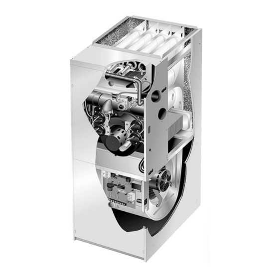
- Page 7 G61MP PARTS ARRANGEMENT TOP CAP DuralokPlus HEAT EXCHANGER ASSEMBLY CABINET BURNER BOX ASSEMBLY GAS VALVE AND MANIFOLD FLUE COLLAR COMBUSTION AIR PROVE PROVE WARM HEADER SWITCHES* (COLLECTOR) COMBUSTION AIR INDUCER CONDENSER COIL BURNER PRIMARY LIMIT ACCESS PANEL COLD HEADER (COLLECTOR) BLOWER DOOR ACCESS...
- Page 8 4. Integrated Control Board (A92) forming any service procedure. All G61MP units are equipped with the Lennox Two−Stage Integrated control board. The system consists of a igni- A−Control Box tion control board (figure 4 with control terminal designa- tions in tables 3, 4 and 5) and ignitor (figure 7).
- Page 9 onds. After a total of five trials for ignition (including the ini- TABLE 1 tial trial), the control goes into Watchguard−Flame Failure Heating Fan Off Delay mode. After a 60−minute reset period, the control will begin the ignition sequence again. Delay (Seconds) Switch 1 Switch 2...
- Page 10 TABLE 3 TWO−STAGE INTEGRATED CONTROL BOARD Integrated Control Board Terminals 120VAC Neutral LINE Line XFMR Transformer LEDs Electronic Air Cleaner CIRC Indoor Blower SWITCHES 1 − 4 Humidifier 120VAC Line Humidifier XMFR Transformer LINE Line PARK For Unused Leads COOL Cooling Speed Electronic Air Cleaner HI HEAT...
- Page 11 TABLE 6 DIAGNOSTIC CODES Diagnostic LEDs are labeled DS1 and DS2. See figure 4 for location of diagnostic LEDs. DESCRIPTION Power on − Normal operation. SIMULTANEOUS SIMULTANEOUS Also signaled during cooling and continuous fan. SLOW FLASH SLOW FLASH SIMULTANEOUS SIMULTANEOUS Normal operation −...
-
Page 12: Flame Sensor
C−Heating Components 4. Ignitor The SureLight ignitor is made of durable silicon nitride. Ig- 3. Flame Sensor nitor longevity is enhanced by controlling voltage to the ig- A flame sensor is located on the left side of the burner sup- nitor. - Page 13 LPG change over kit s are available from Lennox. Kits include The combustion air inducer pulls fresh air through the air burner orifices and a gas valve regulator conversion kit.
- Page 14 On heat demand (first or second stage) the switch senses 1 − Remove thermostat demand and allow unit to cycle off. that the combustion air inducer is operating. It closes a cir- cuit to the furnace control when pressure inside the cold 2 −...
- Page 15 12. Combustion Air Inducer (B6) TABLE 8 0’ to 4500’ All G61MP units use a combustion air inducer to move air Set Point Set Point through the burners and heat exchanger during heating G61MP Unit Second Stage First Stage operation. The blower uses a PSC 120VAC motor. The −045 motor operates during all heating operation and is con- 0 95"...
- Page 16 II−PLACEMENT AND INSTALLATION TABLE 11 OUTDOOR TERMINATION KITS AND CORRESPONDING EQUIVALENCIES Vent Pipe Length Equivalency (feet) Outdoor Outdoor 2" Wall Exhaust Exhaust 1−1/2" 2" Con- 3" Con- VENT 2" Wall 3" Wall 2" Wall Kit with Accelerator Accelerator Concen- centric centric PIPE UNIT...
- Page 17 A−Vent Piping Guidelines *NOTE − The exhaust pipe should be offset a minimum of 12 inches to avoid the possibility of water droplets being re- The G61MP can be installed as either a Non−Direct Vent leased from the exhaust termination. The minimum ex- or a Direct Vent gas central furnace.
- Page 18 Use the following steps to correctly size vent pipe diameter. B−PVC Joint Cementing Procedure 1 − Determine the vent termination and its corresponding All cementing of joints should be done according to the equivalent feet value according to table 11. specifications outlined in ASTM D 2855.
- Page 19 C− Venting Practices 3. In areas where piping penetrates joists or interior walls, hole must be large enough to allow clearance on The thickness of construction through which vent pipes all sides of pipe through center of hole using a hanger. may be installed is 24"...
- Page 20 TYPICAL EXHAUST PIPE CONNECTIONS CAUTION HORIZONTAL DIRECT OR NON-DIRECT VENT APPLICATIONS Do not discharge exhaust into an existing stack or (Horizontal Right-Hand Air stack that also serves another gas appliance. If verti- Discharge Application Shown) cal discharge through an existing unused stack is re- quired, insert PVC pipe inside the stack until the end is even with the top or outlet end of the metal stack.
- Page 21 TYPICAL AIR INTAKE PIPE CONNECTIONS 2−1/2", UPFLOW OR DOWNFLOW DIRECT VENT APPLICATIONS 3" OR (Right-Hand Exit in Upflow Application Shown) 2−1/2", REDUCER 3" OR REDUCER 2"* PLUG (Must be G61MP−36B−045 G61MP−36B−045 G61MP−36B−045 glued in G61MP−36B−070 G61MP−36B−070 G61MP−36B−070 place) G61MP−48C−090 G61MP−48C−090 G61MP−48C−090 G61MP−60C−090 G61MP−60C−090...
- Page 22 TYPICAL AIR INTAKE PIPE CONNECTIONS DOWNFLOW NON-DIRECT VENT APPLICATIONS (Right-Hand Exit in Downflow Applications Shown) 2" SWEEP INTAKE DEBRIS SCREEN (Provided) 6 in. Max. PLUG PLUG (Must be glued in (Must be place) glued in place) 2" 18 in. 2" SWEEP ELL INTAKE DEBRIS SCREEN (Provided)
- Page 23 Heating cable installation kit is avail- vents when tested as indicated in step 3, return able from Lennox. See Condensate Piping section for part doors, windows, exhaust fans, fireplace dampers numbers.
- Page 24 VENT TERMINATION CLEARANCES FOR INSTALLATIONS IN THE USA AND CANADA* − G61MP VENT TERMINATION − AIR INLET OF OTHER APPLIANCE less than 10 ft (3.048M) A − Clearance above grade − 12 in. (305mm) minimum. E − Clearance to non−mechanical air supply inlet or outlet for vent installations in USA −...
- Page 25 Details of Intake and Exhaust Piping Terminations for 9. Based on the recommendation of the manufacturer, a Direct Vent Installations multiple furnace installation may use a group of up to four termination kits WTK assembled together hori- NOTE − In Direct Vent installations, combustion air is taken zontally, as shown in figure 26.
- Page 26 EXHAUST VENT EXHAUST 12" (305) ABOVE TERMINATION AVERAGE SNOW ACCUMULATION Inches (mm) Front View INTAKE INTAKE VENT TERMINATION 1/2" (13) Foam Insulation Side View in Unconditioned Space FIELD−PROVIDED REDUCER MAY BE REQUIRED FIELD− TO ADAPT LARGER VENT PROVIDED EXHAUST VENT PIPE SIZE TO TERMINATION REDUCER MAY BE REQUIRED...
- Page 27 12" (305) MAX. for 2" (51) 20" (508) MAX. for 3" (76) Inches (mm) COVER EXHAUST (unless supported) 12" VENT WITH (305) 1/2" (13) EXHAUST FOAM INSULATION 8" (203) INTAKE INTAKE Minimum EXHAUST 12" (305) Minimum 12" MIN. 5" ABOVE GRADE (127) (305) Above Grade...
- Page 28 3. If exhaust piping must be run up a side wall to position CONDENSATE TRAP LOCATIONS above snow accumulation or other obstructions, pip- (Unit shown in upflow position) ing must be supported every 3 feet (.9m) as shown in figure 12. Refer to figure 31 for proper piping method. Horizontal Horizontal When exhaust piping must be run up an outside wall,...
- Page 29 CONDENSATE ASSEMBLY blockage of drain line. If this is not possible, a heat cable kit may be used on the condensate trap and line. HI/LO SCREWS Heating cable kit is available from Lennox in various (DO NOT use power VENT O−RINGS lengths;...
- Page 30 III−START-UP WARNING A−Preliminary and Seasonal Checks 1 − Inspect electrical wiring, both field and factory installed If you do not follow these instructions exactly, a fire for loose connections. Tighten as required. or explosion may result causing property damage, 2 − Check voltage at disconnect switch. Voltage must be personal injury or death.
- Page 31 IV−HEATING SYSTEM SERVICE CHECKS WHITE RODGERS 36E SERIES GAS VALVE A−C.S.A. Certification HIGH FIRE All units are C.S.A. (formally A.G.A. and C.G.A. combined) MANIFOLD design certified without modifications. Refer to the G61MP PRESSURE Installation Instruction. ADJUSTMENT ON SIDE B−Gas Piping (under cap) CAUTION MANIFOLD...
- Page 32 Gas Leak Detector is strongly recommended. It is available 6 − Repeat steps 3, 4 and 5 on high heat. through Lennox under part number 31B2001. See Corp. NOTE − Shut unit off and remove manometer as soon as an 8411−L10, for further details.
- Page 33 TABLE 17 H− High Altitude High Heat NOTE − In Canada, certification for installations at eleva- Unit For Nat For L.P. tions over 4500 feet (1372 m) is the jurisdiction of local au- G61MP−36B−045 6.5 − 7.5 7.4 − 8.4 thorities.
- Page 34 3 − Depending on the type of indoor thermostat, blower TRANSDUCER #78H5401 available from and entire unit will be off when the system switch is in (PART #78H5401) Lennox Repair Parts) is OFF position. required to measure flame B−Temperature Rise signal if meter used will not...
- Page 35 D−Blower Speed Taps Filters Filters should be inspected monthly. Clean or replace the Blower speed tap changes are made on the SureLight con- trol board. See figure 4. The unused tap must be secured filters when necessary to ensure proper furnace opera- on dummy terminals "PARK "...
- Page 36 20 − Back wash heat exchanger with soapy water solution G61MP−135 ONLY or steam. If steam is used it must be below 275°F (135°C) . 21 − Thoroughly rinse and drain the heat exchanger. Soap Remove and discard two shipping screws. solutions can be corrosive.
- Page 37 Cleaning the Burner Assembly 7 − Reconnect the sensor wire and reconnect the 2−pin 1 − Turn off electrical and gas power supplies to furnace. plug to the ignitor wiring harness. Remove upper and lower furnace access panels. 8 − Reinstall the burner box assembly using the existing 2 −...
- Page 38 VII− Wiring and Sequence of Operation Page 38...
- Page 39 Sequence of Operation Single−Stage Thermostat, Two Stage Heat. Jumper E20 set at SINGLE" Sequence depends on type thermostat used. G61MP 1− SureLight control energizes combustion air inducer B6 units are applicable for single stage or two stage ther- on low heat speed. Combustion air inducer runs until mostats.
- Page 40 HEATING SEQUENCE OF OPERATION NORMAL AND ABNORMAL HEATING MODE GAS VALVE OFF. COMBUSTION AIR INDUCER POWER ON OFF. INDOOR BLOWER OFF. CHECK FOR BROKEN IGNITOR OR OPEN IGNITER CIRCUIT. DS1 AND DS2 ALTERNATING FAST FLASH. CONTROL SELF−CHECK OKAY? GAS VALVE OFF. COMBUSTION AIR INDUCER OFF. INDOOR BLOWER OFF.
- Page 41 HEATING SEQUENCE OF OPERATION CONTINUED THERMOSTAT CALLS FOR HEAT DS1 AND DS2 SIMULTANEOUS FAST FLASH (Refer to box A on previous page) FIRST−STAGE (LOW FIRE) PRESSURE GAS VALVE OFF. COMBUSTION AIR INDUCER SWITCH CLOSED WITHIN 2.5 MINUTES? OFF. INDOOR BLOWER OFF. UNIT WILL RETRY AFTER 5−MINUTE WAIT PERIOD.
- Page 42 HEATING SEQUENCE OF OPERATION CONTINUED THERMOSTAT CALLS FOR HEAT. DS1 AND DS2 SIMULTANEOUS FAST FLASH. SEE BOX A. FLAME SIGNAL ABOVE (u0.22 microamps) LOW FLAME SIGNAL (Does not affect control operation) DS1 SLOW FLASH, DS2 FAST FLASH. SINGLE−STAGE THERMOSTAT MODE TWO STAGE THERMOSTAT MODE (E20 SET AT SINGLE") (E20 SET AT TWO")
- Page 43 HEATING SEQUENCE OF OPERATION CONTINUED SEE BOX A NORMAL OPERATION DS1 AND DS2 SIMULTANEOUS SLOW FLASH. SEE BOX B THERMOSTAT CALLS FOR HEAT DS 1 AND DS 2 SIMULTANEOUS FAST FLASH GAS VALVE OFF. COMBUSTION AIR INDUCER OFF. INDOOR BLOWER ON. ARE PRIMARY, SECONDARY, ROLLOUT AND DS1 SLOW FLASH, DS2 ON.
- Page 44 COOLING SEQUENCE OF OPERATION POWER ON IS POLARITY REVERSED? SIGNAL POLARITY REVERSED. DS1 FAST FLASH, DS2 SLOW FLASH. SIGNAL IMPROPER GROUND AT DS. IS THERE IS VOLTAGE LOW VOLTAGE SIGNAL AT DS HOLDS SIGNAL HOLDS PROPER GROUND? ABOVE 75 VOLTS? UNTIL VOLTAGE RISES ABOVE 75 VOLTS.
- Page 45 CONTINUOUS LOW SPEED FAN SEQUENCE OF OPERATION MANUAL FAN SELECTION MADE AT THERMOSTAT. AFTER 2 SECOND DELAY, INDOOR BLOWER IS ENERGIZED ON CONTINUOUS FAN SPEED (LOW HEAT / LOW COOL). THERMOSTAT CALLS FOR FIRST STAGE COOL. THERMOSTAT CALLS FOR FIRST−STAGE HEAT. COMPRESSOR IS ENERGIZED AND INDOOR BURNERS IGNITE AND INDOOR BLOWER BLOWER CONTINUES TO OPERATE IN LOW...
- Page 46 VIII− Field Wiring Applications and Jumper Settings Field Wiring Applications Jumper Settings (See figure 4) Thermostat Wiring Connections W915 Y1 to Y2 1 Heat / 1 Cool SINGLE Leave Installed CONTROL OUTDOOR T’STAT TERM. STRIP UNIT NOTE − Use dip switch 3 to set second−stage heat HSXB15 ON delay.
- Page 47 Field Wiring Applications (Continued) Jumper Settings (See figure 4) Thermostat Wiring Connections W915 Y1 to Y2 FM21 Heat Pump / 1 SINGLE Leave Installed CONTROL FM21 TERM. STRIP Cool *Disconnect existing furnace transformer and re- place with 75VA, 24V trans- former if defrost option to be used.
- Page 48 ® IX−SURELIGHT CONTROL TROUBLESHOOTING CHART UPON INITIAL POWER UP, REMOVE ALL THERMOSTAT DEMANDS TO THE UNIT PROBLEM: 1 UNIT FAILS TO OPERATE IN THE COOLING, HEATING, OR CONTINUOUS FAN MODE Condition Possible Cause Corrective Action / Comments 1.1.1 ACTION 1 − Check 120V main voltage. −...
- Page 49 PROBLEM 1: UNIT FAILS TO OPERATE IN THE COOLING, HEATING, OR CONTINUOUS FAN MODE Condition Possible Cause Corrective Action / Comments ACTION 1 − Check that the unit is properly 1.5.1 ground. − Diagnostic lights flash the improper ACTION 2 − Install a proper main ground to the Improper ground to the unit.
- Page 50 PROBLEM 2: UNIT FAILS TO FIRE IN THE HEATING MODE, COMBUSTION AIR INDUCER DOES NOT ENERGIZE (CONT.). Condition Possible Cause Corrective Action/Comments 2.3.1 − Unit operates with a cooling and con- ACTION 1 − Check for correct wiring and loose tinuous fan demand.
- Page 51 PROBLEM 4: UNIT FAILS TO FIRE IN THE HEATING MODE, COMBUSTION AIR BLOWER ENERGIZES, IGNITOR IS ENERGIZED. Condition Possible Cause Corrective Action/Comments ACTION 1 − Check line pressure at the gas valve. 4.1.1 Pressure should not exceed 13" WC for both nat- −...
- Page 52 ACTION 2 − Seal leakage if possible, replace secondary heat exchanger, and heat exchanger if necessary, tag and return heat exchanger to proper Lennox personnel. combustion air blower. 5.3.4 ACTION 1 − Check for sooting deposits or other restrictions in the heat exchanger assembly.
- Page 53 PROBLEM 6: CONTROL SIGNALS LOW FLAME SENSE DURING HEATING MODE Condition Possible Cause Corrective Action/Comments 6.1.1 ACTION 1 − Check the sensor rod for proper loca- − Unit operates correctly but the diag- tion on the burner. Properly locate the sensor rod Sensor rod is improperly located on or replace if rod cannot be located correctly.
- Page 54 SERVICE NOTES Page 54...