Table of Contents
Advertisement
E 2009 Lennox Industries Inc.
Dallas, Texas, USA
THIS MANUAL MUST BE LEFT WITH THE
HOMEOWNER FOR FUTURE REFERENCE
Do not store or use gasoline or other
flammable vapors and liquids in the
vicinity of this or any other ap-
pliance.
Installation and service must be
performed by a qualified installer,
service agency or the gas supplier.
08/09
*2P0809*
INSTALLATION
INSTRUCTIONS
G61MP SERIES UNITS
GAS UNITS
506406−01
08/2009
Supersedes 505,124M
Table of Contents
WARNING
FIRE OR EXPLOSION HAZARD.
Failure to follow safety warnings exact-
ly could result in serious injury, death,
or property damage.
WHAT TO DO IF YOU SMELL GAS:
D Do not try to light any appliance.
D Do not touch any electrical switch; do not
use any phone in your building.
D Leave the building immediately.
D Immediately call your gas supplier from a
neighbor's phone. Follow the gas supplier's
instructions.
D If you cannot reach your gas supplier, call
the fire department.
Page 1
. . . . . . . . . . . . . . . . . . . . . . . . . . . . . . .
. . . . . . . . . . . . . . . . . . . . . .
. . . . . . . . . . . . . . . . . . . . . .
. . . . . . . . . . . . . . . . . . . . . . . . . . . . .
. . . . . . . . . . . . . . . . . . . . . . . . . . . . . . . . . . . . . .
. . . . . . . . . . . . . . . . . . . . . . . . . . . . . . . . . . . . . . . .
. . . . . . . . . . . . . . . . . . . . . . . . . . . . . . . . . .
. . . . . . . . . . . . . . . . . . . .
. . . . . . . . . . . . . . . . . . . . . . . . .
. . . . . . . . . . . . . . . . . . . . .
. . . . . . . . . . . . . . . . . . . . . . . . . . . . . .
. . . . . . . . . . . . . . . . . . . . . . . . . . . . . . . . . . .
. . . . . . . . . . . . . . . . . . . . . . . . . . . . . . . . . . . . .
. . . . . . . . . . . . . . . . . . . . . . .
. . . . . . . . . . . . . . . . . . . . . . . . . . . . . . . . . .
. . . . . . . . . . . . . . . . . . . . . .
. . . . . . . . . . . . . . . . . . . . . . .
. . . . . . . . . . . . . . . . . . . . . . . . .
. . . . . . . . . . . . . . . . . . . . . . . . . . . . . . . . . . . . . .
. . . . . . . . . . . . . . . . . . . . . . . . . . . . . . .
. . . . . . . . . . . . . . . . . . . . . . . . . . . . . .
. . . . . . . . . . . . . . . . . . . . .
*P506406-01*
Litho U.S.A.
2
3
4
4
. . . . . . . . . . .
5
6
. . . . . . . . . . . .
6
. . . . . . . . . . . . . . . . . .
8
16
16
16
18
20
21
33
35
42
42
44
45
46
53
. . . . . . . . . .
56
57
62
63
. . . . . . . . . . . . . .
63
506406−01
Advertisement
Table of Contents
Troubleshooting

Related Manuals for Lennox G61MP?36B?045


Summary of Contents for Lennox G61MP?36B?045
-
Page 1: Table Of Contents
INSTALLATION INSTRUCTIONS E 2009 Lennox Industries Inc. Dallas, Texas, USA G61MP SERIES UNITS GAS UNITS 506406−01 08/2009 Litho U.S.A. Supersedes 505,124M Table of Contents Unit Dimensions ....... -
Page 2: Unit Dimensions
G61MP Unit Dimensions − inches (mm) *NOTE − 60C and 60D size units installed in upflow ap- plications that require air volumes over 1800 cfm (850 L/s) must have one of the following: 1. Single side return air with transition, to accommodate SUPPLY AIR 20 x 25 x 1 in. -
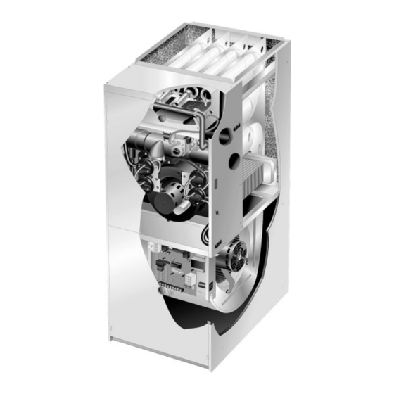
Page 3: G61Mp Parts Identification
G61MP Parts Arrangement G61MP PARTS IDENTIFICATION TOP CAP DuralokPlus HEAT EXCHANGER ASSEMBLY CABINET BURNER BOX ASSEMBLY GAS VALVE AND MANIFOLD FLUE COLLAR COMBUSTION AIR PRESSURE WARM HEADER PROVE SWITCHES* (COLLECTOR) COMBUSTION AIR INDUCER CONDENSER COIL BURNER PRIMARY LIMIT ACCESS PANEL COLD HEADER (COLLECTOR) BLOWER... -
Page 4: Shipping And Packing List
NOTE − G61MP−48C−110, G61MP−60C−110 G61MP Gas Furnace G61MP−60C−111 units also include a 2" diameter PVC The G61MP category IV gas furnace is shipped ready for street elbow, which is shipped on the blower deck in the installation in the upflow, downflow, horizontal left air dis- heating compartment. -
Page 5: Use Of Furnace As Construction Heater
NOTE − Furnace must be adjusted to obtain a temperature rise within the range specified on the unit nameplate. Failure Lennox does not recommend the use of G61MP units as a to do so may cause erratic limit operation. construction heater during any phase of construction. Very low return air temperatures, harmful vapors and operation This G61MP furnace may be used as a high−static unit... -
Page 6: General
You must consider combustion air supervisor. needs and requirements for exhaust vents and gas pip- Lennox Industries Inc. ing. A portion of this information has been reprinted with P.O. Box 799900 Dallas, TX 75379−9900 permission from the National Fuel Gas Code (ANSI−... - Page 7 Z223.1/NFPA 54). This reprinted material is not the com- which are sealed to the furnace casing and which terminate plete and official position of the ANSI on the referenced outside the space containing the furnace. This is especially subject, which is represented only by the standard in its important when the furnace is mounted on a platform in a entirety.
-
Page 8: Installation − Setting Equipment
in the enclosure. See figures 4 and 5. When communicat- EQUIPMENT IN CONFINED SPACE − ALL AIR FROM OUTSIDE ing with the outdoors through horizontal ducts, each open- (Inlet Air from Crawl Space and Outlet Air to Ventilated Attic) ing shall have a minimum free area of 1 square inch (645 VENTILATION LOUVERS ) per 2,000 Btu (.56 kW) per total input rating of all (Each end of attic) - Page 9 SETTING EQUIPMENT UPFLOW APPLICATION DOWNFLOW APPLICATION UNIT MUST BE LEVEL SIDE−TO−SIDE IN ALL APPLICATIONS. AIR FLOW HORIZONTAL APPLICATION AIR FLOW AIR FLOW FRONT VIEW FRONT VIEW FRONT VIEW AIR FLOW UNIT FRONT UNIT UNIT FRONT FRONT 1/2" max. AIR FLOW END VIEW 1/2"...
- Page 10 Upflow Applications Return Air −− Upflow Units Return air can be brought in through the bottom or either The G61MP gas furnace can be installed as shipped in the upflow position. Refer to figure 8 for clearances. side of the furnace installed in an upflow application. If the furnace is installed on a platform with bottom return, make Installation Clearances an airtight seal between the bottom of the furnace and the...
- Page 11 Optional Return Air Base (Upflow Applications Only −− For use with B, C and D cabinets only) 23 (584) Overall (102) Minimum (Maximum) 11 (279) (356) 22−7−16 Maximum Unit side return air (570) 14 (356) AIR FLOW Opening Overall FURNACE (Maximum) FRONT SIDE RETURN...
- Page 12 Setting an Upflow Unit Refer to figure 13 for clearances in downflow applica- tions. When the side return air inlets are used in an upflow ap- plication, it may be necessary to install leveling bolts on the Downflow Application Installation Clearances bottom of the furnace.
- Page 13 Installation on Combustible Flooring Installation on Cooling Coil Cabinet (Using an Additive Base) 1 − Refer to reverse−flow coil installation instructions for 1 − When unit is installed on a combustible floor, an addi- correctly sized opening in floor and installation of cabi- tive base must be installed between the furnace and net.
- Page 14 Horizontal Applications 3 − If unit is installed above finished space, fabricate a drain pan fitted with a 1/2 inch or 3/4 inch N.P.T. fitting. The G61MP furnace can be installed in horizontal applica- tions with either right− or left−hand air discharge. 4 −...
- Page 15 Lennox part number 56J18). Position the support Unit Heater Discharge Duct Guidelines frame on top of the blocks and install the unit on the A field−fabricated and installed discharge air duct and grille frame. Leave 5−1/2 inches for service clearance for cabinet is suitable for use with the G61MP heater.
-
Page 16: Filters
Filters Pipe & Fittings Specifications This unit is not equipped with a filter or rack. A field−pro- All pipe, fittings, primer and solvent cement must conform with American National Standard Institute and the Ameri- vided filter is required for the unit to operate properly. Table can Society for Testing and Materials (ANSI/ASTM) stan- 3 lists recommended filter sizes. - Page 17 Table 5 lists the available exhaust termination kits, as well as vent pipe equivalencies which must be used when siz- ing vent pipe. All Lennox vent terminations are PVC. TABLE 5 OUTDOOR TERMINATION KITS AND CORRESPONDING EQUIVALENCIES...
-
Page 18: Vent Piping Guidelines
Refer to table 8. Contact Lennox’ Application Department for more infor- *NOTE − The exhaust pipe should be offset a minimum of mation concerning sizing of vent systems which include 12 inches to avoid the possibility of water droplets being re- multiple pipe sizes. - Page 19 Use the following steps to correctly size vent pipe diameter. TABLE 7 MAXIMUM VENT PIPE LENGTHS Refer to Vent Pipe Size Determination Worksheet on page 53. MAXIMUM EQUIVALENT VENT LENGTH FEET 1 − Determine the vent termination and its corresponding G61MP ALTITUDE MODEL...
-
Page 20: Joint Cementing Procedure
NOTE − Furnace flue collar and air inlet fitting are both Joint Cementing Procedure made of ABS material. Use transition solvent cement when bonding ABS to either PVC or CPVC, refer to the All cementing of joints should be done according to the procedure specified in ASTM D3138.. -
Page 21: Venting Practices
4 − Isolate piping at the point where it exits the outside wall Venting Practices or roof in order to prevent transmission of vibration to The thickness of construction through which vent pipes the structure. may be installed is 24" (610mm) maximum and 3" (76mm) 5 −... - Page 22 CAUTION TYPICAL EXHAUST PIPE CONNECTIONS HORIZONTAL DIRECT OR NON−DIRECT VENT APPLICATIONS Do not discharge exhaust into an existing stack or (Horizontal Right−Hand Air stack that also serves another gas appliance. If verti- Discharge Application Shown) cal discharge through an existing unused stack is re- quired, insert PVC pipe inside the stack until the end * 2"...
- Page 23 TYPICAL AIR INTAKE PIPE CONNECTIONS UPFLOW OR DOWNFLOW DIRECT VENT APPLICATIONS (Right−Hand Exit in Upflow Application Shown) 2−1/2", 3" OR 2−1/2", TRANSITION 3" OR TRANSITION *2" PLUG (Must be −36B−045− glued in −36B−070 place) −36B−045 −36B−045 −36B−071 −36B−070 −36B−070 −48C−090 −36B−071 −36B−071 −60C−090...
- Page 24 TYPICAL AIR INTAKE PIPE CONNECTIONS DOWNFLOW NON−DIRECT VENT APPLICATIONS (Right−Hand Exit in Downflow Applications Shown) 2" SWEEP INTAKE DEBRIS SCREEN (Provided) 6 in. Max. PLUG PLUG (Must be glued in (Must be place) glued in place) 2" 18 in. 2" SWEEP ELL INTAKE DEBRIS SCREEN (Provided)
- Page 25 National Fuel prevent freeze−ups. Heating cable installation kit is avail- Gas Code ANSI Z223−1/NFPA 54 in U.S.A., and current able from Lennox. See Condensate Piping section for part CSA−B149 Natural Gas and Propane Installation Codes in numbers.
-
Page 26: Vent Termination Clearances
‡ Permitted only if veranda, porch, deck or balcony is fully open on a minimum of two sides beneath the floor. Lennox recommends avoiding this location if possible. FIGURE 29 Page 26... - Page 27 ‡ Permitted only if veranda, porch, deck or balcony is fully open on a minimum of two sides beneath the floor. Lennox recommends avoiding this location if possible. FIGURE 30 Page 27...
- Page 28 Details of Intake and Exhaust Piping Terminations for TABLE 8 EXHAUST PIPE TERMINATION SIZE REDUCTION Direct Vent Installations G61MP Exhaust Pipe Size Termination Pipe Size NOTE − In Direct Vent installations, combustion air is taken MODEL from outdoors and flue gases are discharged to outdoors. 045, 070, −071 2", 2−1/2", 3"...
-
Page 29: Front View
EXHAUST VENT EXHAUST 12" (305) ABOVE TERMINATION AVERAGE SNOW ACCUMULATION Inches (mm) Front View INTAKE INTAKE VENT TERMINATION 1/2" (13) Foam Insulation Side View in Unconditioned Space FIELD−PROVIDED REDUCER MAY BE REQUIRED FIELD− TO ADAPT LARGER VENT PROVIDED EXHAUST VENT PIPE SIZE TO TERMINATION REDUCER MAY BE REQUIRED... -
Page 30: Front View
12" (305) MAX. for 2" (51) 20" (508) MAX. for 3" (76) Inches (mm) COVER EXHAUST (unless supported) 12" VENT WITH (305) 1/2" (13) EXHAUST FOAM INSULATION 8" (203) INTAKE INTAKE Minimum Minimum 12" EXHAUST (305) above grade or average snow Minimum 12"... - Page 31 3 − If exhaust piping must be run up a side wall to position sate trap should extend below the unit. A 5−1/2" service above snow accumulation or other obstructions, pip- clearance is required for the condensate trap. Refer to fig- ing must be supported every 3 feet (.9m) as shown in ure 44 for condensate trap locations.
- Page 32 CLEAN−OUT ACCESS (both sides) Heating cable kit is available from Lennox in various lengths; 6 ft. (1.8m) − kit no. 26K68; 24 ft. (7.3m) − kit CONDENSATE TRAP no. 26K69; and 50 ft. (15.2m) − kit no. 26K70.
-
Page 33: Gas Piping
Gas Piping IMPORTANT CAUTION Compounds used on threaded joints of gas piping must be resistant to the actions of liquified petro- If a flexible gas connector is required or allowed by leum gases. the authority that has jurisdiction, black iron pipe shall be installed at the gas valve and extend outside the furnace cabinet. - Page 34 Horizontal Applications Possible Gas Piping Configerations MANUAL MAIN SHUT−OFF Horizontal Application VALVE Left−Side Air Discharge MANUAL MAIN SHUT−OFF VALVE GROUND JOINT UNION GROUND JOINT DRIP LEG UNION DRIP LEG MANUAL MAIN SHUT−OFF Horizontal Application VALVE Right−Side Air Discharge (With 1/8 in. NPT Plugged Tap Shown) GROUND...
-
Page 35: Electrical
The unit is equipped with a field make−up box. The make− Electrical up box may be moved to the right side of the furnace to fa- ELECTROSTATIC DISCHARGE (ESD) cilitate installation. If the make−up box is moved to the right Precautions and Procedures side, the excess wire must be pulled into the blower compartment. - Page 36 9 − One 24V H" terminal is provided on the furnace control Indoor Blower Speeds board terminal block. Any humidifier rated up to 0.5 1 − When the thermostat is set to FAN ON," the indoor amp can be connected to this terminal with the ground blower will run continuously on the low heat speed leg of the circuit being connected to either ground or when there is no cooling or heating demand.
- Page 37 TABLE 10 Field Wiring Applications DIP Switch Settings and On−Board Links (Figure 52) W915 W951 Thermostat Wiring Connections (Y1 to Y2) DIP Switch 1 (O to R) Two−Stage Heat Pumps Cooling 1 Heat / 1 Cool Intact Intact CONTROL OUTDOOR T’STAT TERM.
- Page 38 TABLE 10 Field Wiring Applications (Continued) DIP Switch Settings and On−Board Links (Figure 52) W915 W951 Thermostat Wiring Connections (Y1 to Y2) DIP Switch 1 (O to R) Two−Stage Heat Pumps Cooling 2 Heat / 2 Cool Intact CONTROL OUTDOOR T’STAT TERM.
- Page 39 TWO−STAGE INTEGRATED CONTROL BOARD 1/4" QUICK CONNECT TERMINALS SENSE = 120 VAC OUTPUT TO FLAME SENSER NEUTRALS= 120 VAC NEUTRAL PARK = DEAD TERMINAL FOR UNUSED BLOWER LEAD HEAT LOW = 120 VAC OUTPUT TO CIRC BLWR −− LOW HT SPEED AND CONTINUOUS FAN HEAT HIGH/ COOL LOW = 120 VAC OUTPUT TO CIRC BLWR −−...
- Page 40 INTEGRATED CONTROL BOARD DIP SWITCH SETTINGS AND JUMPERS FIGURE 53 Page 40...
- Page 41 TYPICAL G61MP WIRING DIAGRAM FIGURE 54 Page 41...
-
Page 42: Integrated Control Board
TABLE 11 Integrated Control Board Heating Blower−Off Delay Switch Settings G61MP units are equipped with a two−stage integrated Blower Off Delay Switch 3 Switch 4 control. This control manages ignition timing and fan off (Seconds) delays based on selections made using the control DIP switches and jumpers. - Page 43 4 − This furnace is equipped with an ignition device which CAUTION automatically lights the burners. Do not try to light the burners by hand. Before attempting to perform any service or mainte- 5 − Remove the upper access panel. nance, turn the electrical power to unit OFF at dis- 6 −...
-
Page 44: Gas Pressure Adjustment
Use pressure test NOTE − Shut unit off and remove manometer as soon as an adapter kit (available as Lennox part 10L34) to assist in accurate reading has been obtained. Take care to remove measurement. -
Page 45: High Altitude Information
TABLE 13 Manifold Pressure (Outlet) inches w.c. Altitude (feet) 0−2000 2001−4500 4501−5500 5501−6500 6501−7500 7501−10000 Model Number Fuel High High High High High High Fire Fire Fire Fiire Fire Fiire Fire Fiire Fire Fiire Fire Fiire Natural 045, 070, 090, 110, Propane 4.9 10.0 10.0... -
Page 46: Other Unit Adjustments
Testing for Proper Venting and Sufficient Combustion Air for Non−Direct Vent Applications sufficient combustion/make-up air must be provided. WARNING The venting system should be re-sized to approach the minimum size as determined by using the ap- CARBON MONOXIDE POISONING HAZARD! propriate tables in appendix G in the current standards of the National Fuel Gas Code ANSI−Z223.1/NPFA 54 Failure to follow the steps outlined below for each... - Page 47 2 − Check for the correct voltage at the furnace (furnace sure. After one hour of continuous thermostat demand for operating). heat, the Watchguard will break and remake thermostat de- mand to the furnace and automatically reset the control to 3 −...
-
Page 48: Blower Performance Data
Blower Performance Data G61MP−36B−045 PERFORMANCE (Less Filter) G61MP−48C−090 PERFORMANCE (Less Filter) Air Volume / Watts at Different Blower Speeds Air Volume / Watts at Different Blower Speeds External External Static Medium− Medium− Static Medium− Medium− High High High High Pressure Pressure in. - Page 49 G61MP−60C−090 PERFORMANCE (Less Filter) Air Volume / Watts at Different Blower Speeds Bottom Return Air, Side Return Air with Optional RAB Single Side Return Air − Air volumes in bold require field External Return Air Base, Return Air from Both Sides or Return fabricated transition to accommodate 20 x 25 x 1 in.
- Page 50 Blower Performance Data G61MP−60C−110 PERFORMANCE (Less Filter) Air Volume / Watts at Different Blower Speeds Air Volume / Watts at Different Blower Speeds Bottom Return Air, Side Return Air with Optional RAB Single Side Return Air − Air volumes in bold require field External Return Air Base, Return Air from Both Sides or Return fabricated transition to accommodate 20 x 25 x 1 in.
- Page 51 G61MP−60D−135 PERFORMANCE (Less Filter) Air Volume / Watts at Different Blower Speeds Air Volume / Watts at Different Blower Speeds Bottom Return Air, Side Return Air with Optional RAB Single Side Return Air − Air volumes in bold require field External Return Air Base, Return Air from Both Sides or Return fabricated transition to accommodate 20 x 25 x 1 in.
-
Page 52: Heating Sequence Of Operation
Applications Using A Single−Stage Thermostat Heating Sequence of Operation B − Heating Sequence −− Control Board Thermostat NOTE − The thermostat selection DIP switch on the control Selection DIP switch in Single−Stage" Position board is factory−set in the TWO−STAGE" position. NOTE −... -
Page 53: Service
3 − Remove the drain plug from the condensate trap and Service empty water. Inspect the trap then reinstall the drain plug. Cleaning Heat Exchanger WARNING If cleaning the heat exchanger becomes necessary, follow the below procedures and refer to figure 1 when disassem- ELECTRICAL SHOCK, FIRE, bling unit. - Page 54 17 − Remove the primary limit from the vestibule panel. 38 − Secure burner box assembly to vestibule panel using four existing screws. Make sure burners line up in 18 − Remove two screws from the front cabinet flange at center of burner ports.
-
Page 55: Planned Service
Return air duct − Must be properly attached and provide Planned Service an air seal to the unit. A service technician should check the following items dur- Operating performance − Unit must be observed during ing an annual inspection. Power to the unit must be shut off operation to monitor proper performance of the unit and the for safety. -
Page 56: Ignition Control Board Diagnostic Codes
Ignition Control Board Diagnostic Codes FLASH CODE STATUS / ERROR DESCRIPTION (X + Y) FLASH CODE DESCRIPTIONS Pulse A 1/4 second flash followed by four seconds of off time. Heartbeat Constant 1/2 second bright and 1/2 second dim cycles. LED flashes X times at 2Hz, remains off for two seconds, flashes Y times at 2Hz, remains off for four X + Y seconds, then repeats. -
Page 57: Troubleshooting
Troubleshooting: Heating Sequence of Operation HEATING SEQUENCE OF OPERATION NORMAL AND ABNORMAL HEATING MODE POWER ON GAS VALVE OFF. COMBUSTION AIR INDUCER OFF. INDOOR BLOWER OFF. (RESET CONTROL BY CONTROL SELF−CHECK OKAY? TURNING MAIN POWER OFF.) POLARITY REVERSED. POLARITY OKAY? STATUS ERROR CODE 5 + 4. - Page 58 Troubleshooting: Heating Sequence of Operation (Continued) HEATING SEQUENCE OF OPERATION CONTINUED THERMOSTAT CALLS FOR HEAT STATUS LED − HEARTBEAT. (Refer to box A on previous page) FIRST−STAGE (LOW FIRE) PRESSURE GAS VALVE OFF. COMBUSTION AIR INDUCER SWITCH CLOSED WITHIN 2.5 MINUTES? OFF.
- Page 59 Troubleshooting: Heating Sequence of Operation (Continued) HEATING SEQUENCE OF OPERATION CONTINUED THERMOSTAT CALLS FOR HEAT. STATUS LED −− HEARTBEAT. SEE BOX A. FLAME SIGNAL ABOVE (u1.40 microamps) LOW FLAME SIGNAL (Does not affect control operation) STATUS ERROR CODE 1 + 2. SINGLE−STAGE THERMOSTAT MODE TWO STAGE THERMOSTAT MODE (DIP SWITCH SET AT SINGLE")
- Page 60 Troubleshooting: Heating Sequence of Operation (Continued) HEATING SEQUENCE OF OPERATION CONTINUED SEE BOX A NORMAL OPERATION. SEE BOX B THERMOSTAT CALLS FOR HEAT. RETURN TO FIRST−STAGE HEAT MODE. FIRST−STAGE CONTINUES UNTIL SECOND− STAGE PRESSURE SWITCH CAN BE PROVEN SECOND−STAGE (HIGH FIRE) HEAT or HEAT DEMAND IS SATISFIED.
-
Page 61: Troubleshooting: Cooling Sequence Of Operation
Troubleshooting: Cooling Sequence of Operation COOLING SEQUENCE OF OPERATION POWER ON SIGNAL POLARITY REVERSED. CONTROL WILL CONTINUE TO CALL FOR COOLING IS POLARITY REVERSED? IN THIS CONDITION. STATUS ERROR CODE 5 + 4. SIGNAL IMPROPER GROUND AT LED. CONTROL WILL CONTINUE TO CALL FOR COOLING IS THERE IN THIS CONDITION. -
Page 62: Repair Parts List
HEAT SPEED. Repair Parts List The following repair parts are available through Lennox dealers. When ordering parts, include the complete furnace model number listed on the CSA nameplate −− Example: G61MP−36B−045−1. All service must be performed by a licensed pro- fessional installer (or equivalent), service agency, or gas supplier. -
Page 63: Vent Pipe Sizing Worksheet
Vent Pipe Sizing Worksheet Step 1 Proposed vent pipe size : ______ Equivalent Feet Step 2 Termination kit catalog number : _____________ Vent pipe equivalency value from table 5 : ______ Step 3 Total number of 90° elbows required (indoors and outdoors) ______ X 5 = ______ equivalent feet of pipe Step 4 Total number of 45°... - Page 64 Requirements for Commonwealth of Massachusetts Modifications to NFPA−54, Chapter 10 4 − INSPECTION. The state or local gas inspector of the side wall, horizontally vented, gas−fueled equipment Revise NFPA−54 section 10.8.3 to add the following re- shall not approve the installation unless, upon inspec- quirements: tion, the inspector observes carbon monoxide detec- For all side wall, horizontally vented, gas−fueled equipment...