
Related Manuals for E-FLITE UMX F4U corsair


Summary of Contents for E-FLITE UMX F4U corsair
- Page 1 ™ F4U Corsair Instruction Manual Bedienungsanleitung Manuel d’utilisation Manuale di Istruzioni...
-
Page 2: Safety Precautions And Warnings
NOTICE All instructions, warranties and other collateral documents are subject to change at the sole discretion of Horizon Hobby, LLC. For up-to-date product literature, visit www.horizonhobby.com and click on the support tab for this product. Meaning of Special Language: The following terms are used throughout the product literature to indicate various levels of potential harm when operating this product: NOTICE: Procedures, which if not properly followed, create a possibility of physical property damage AND little or no possibility of injury. -
Page 3: Table Of Contents
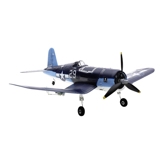
® ™ hank you for purchasing the E-fl ite F4U Corsair, featuring trim schemes from two of the most prolifi c pilots to fl y the prized Corsair, Gregory “Pappy” Boyington and Ira “Ike” Kepford. Now featuring ® AS3X technology, the Ultra Micro F4U Corsair provides the smooth, locked-in fl ight performance that makes this bent-wing warbird feel like a much larger model. -
Page 4: Prefl Ight Checklist
Prefl ight Checklist 1. Charge fl ight battery. 6. Set dual rates and expos. 2. Install fl ight battery in aircraft (once it 7. Adjust center of gravity. has been fully charged). 8. Perform a radio system Range Check. 3. -
Page 5: Battery Charging
Battery Charging Your aircraft comes with a 1S 3.7V DC Li-Po battery charger and 1S 3.7V 150mAh 25C Li-Po battery. Refer to the charging warnings. It is recommended to charge the battery pack while you are inspecting the aircraft. The fl ight battery will be required to confi... -
Page 6: Transmitter Batteries Installation
Transmitter Batteries Installation ® ® Your E-fl ite 4-channel DSM2 ® DSMX RTF transmitter comes pre-bound to the aircraft. Remove the cover, install four of the included batteries (noting proper polarity) and reinstall the cover. Transmitter and Receiver Binding Binding is the process of programming the receiver to recognize the GUID (Globally Unique Identifi er) code ®... -
Page 7: Digital Trims
Transmitter Control Mode 2 Elevator/ Throttle/Rudder Aileron Rudder Trim Aileron Trim Throttle Trim Elevator Trim Mode 1 Throttle/ Elevator/Rudder Aileron Rudder Trim Aileron Trim Elevator Trim Throttle Trim Digital Trims The E-fl ite 4-channel DSM2/DSMX transmitter features digital trim buttons on all controls to make fi ne ®... -
Page 8: Flight Battery Installation And Esc Arming
Flight Battery Installation and ESC Arming Arming the ESC also occurs after binding as previously described, but subsequent connection Lower throttle and of a fl ight battery requires the following steps. throttle trim to lowest settings. AS3X Power ON the ®... -
Page 9: Control Direction Test
Control Direction Test Bind your aircraft and transmitter before doing these tests. Move the controls on the transmitter to make sure aircraft control surfaces move correctly. Always keep throttle at the low position during testing. Down Elevator Elevator Left Aileron Right Aileron Left... -
Page 10: Control Centering
Control Centering Before the fi rst fl ights, or in the event of an accident, make sure the fl ight control surfaces are centered. Adjust the linkages mechanically if the control surfaces are not centered. Use of the transmitter sub-trims may not correctly center the aircraft control surfaces due to the mechanical limits of linear servos. -
Page 11: Flying Tips And Repairs
Flying Tips and Repairs We recommend fl ying your aircraft outside in calm Failure to lower the throttle NOTICE: Always conditions. Always avoid fl ying near houses, trees, stick and trim to the lowest decrease throttle wires and buildings. You should also be careful to possible positions during a at propeller strike. -
Page 12: Landing Gear Removal
Landing Gear Removal To remove the factory-installed landing gear: 1. Lift the end of the landing gear wire above the stop. 2. Gently pull the landing gear toward the center of the wing and away from the clips. Install in reverse order, making sure the end of the landing gear wire is inside the stop and the vertical strut is toward the front of each wing. -
Page 13: Power Components Service
Power Components Service CAUTION: DO NOT handle propeller parts while the fl ight battery is connected. Personal injury could result. Disassembly 1. Disconnect the battery from the ESC/receiver. 2. Carefully cut the tape and decals on the side of the fuselage and behind the canopy to remove the top of the fuselage. -
Page 14: Troubleshooting Guide
Troubleshooting Guide AS3X Problem Possible Cause Solution Control surfaces not at Control surfaces may not have been Center control surfaces mechanically by neutral position when mechanically centered from factory adjusting the U-bends on control linkages transmitter controls are Aircraft was moved after the fl ight battery Disconnect and reconnect the fl... -
Page 15: Limited Warranty
Troubleshooting Guide (Continued) Problem Possible Cause Solution LED on receiver fl ashes Less than a 5-second wait between fi rst Leaving transmitter on, disconnect and rapidly and aircraft will powering on transmitter and connecting reconnect fl ight battery to aircraft not respond to transmit- fl... -
Page 16: Fcc Information
of Horizon. Proof of purchase is required for all warranty tracking and insurance for lost or damaged parcels, as claims. SERVICE OR REPLACEMENT AS PROVIDED Horizon is not responsible for merchandise until it arrives UNDER THIS WARRANTY IS THE PURCHASER’S SOLE AND and is accepted at our facility. -
Page 17: Warranty And Service Information
Warranty and Service Information Country of Purchase Horizon Hobby Phone Number/Email Address Address Horizon Service Center servicecenter.horizonhobby.com/ (Repairs and Repair Requests) RequestForm/ www.quickbase.com/db/ 4105 Fieldstone Rd Horizon Product Support United States of bghj7ey8c?a=GenNewRecord Champaign, Illinois, (Product Technical Assistance) America 888-959-2305 61822 USA sales@horizonhobby.com Sales... -
Page 18: Replacement Parts
Replacement Parts – Ersatzteile – – Pièces de rechange – Pezzi di ricambio – Part # • Nummer Description Beschreibung Description Descrizione Numéro • Codice Decal Sheet: Dekorbogen: Planche de décal- Foglio con decalco- PKZU1602 UM F4U Corsair UM F4U Corsair comanies : UM F4U manie: Corsair... -
Page 19: Optional Parts And Accessories
– Optional Parts and Accessories – – Optionale Bauteile und Zubehörteile – – Pièces optionnelles et accessoires – – Pezzi opzionali e accessori – Part # • Nummer Description Beschreibung Description Descrizione Numéro • Codice Hook and Loop Set Parkzone: Klettband Ultras Micros - Bande Set fascette a strappo PKZ1039... -
Page 20: Decal Application
Decal Application – Dekoraufkleber – – application des décalcomanies – Applicazione decalcomanie – Pappy Boyington Optional 1 Opzione 1... - Page 21 Decal Application – Dekoraufkleber – – application des décalcomanies – Applicazione decalcomanie – Ira Kepford Optional 1 Opzione 1...
- Page 22 © 2014 Horizon Hobby, LLC. E-fl ite, AS3X, Blade, Celectra, UMX, DSM, DSM2, DSMX, ModelMatch, Bind-N-Fly, the Bind-N-Fly logo and the Horizon Hobby logo are trademarks or registered trademarks of Horizon Hobby, LLC. The Spektrum trademark is used with permission of Bachmann Industries, Inc. Futaba is a registered trademark of Futaba Denshi Kogyo Kabushiki Kaisha Corporation of Japan.