Table of Contents
Advertisement
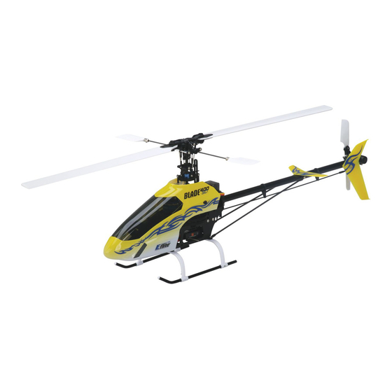
Specifications
Main Rotor Diameter ........................................................................................... 28.2 in (718mm)
Tail Rotor Diameter ................................................................................................ 5.3 in (135mm)
Height ................................................................................................................. 9.0 in (230mm)
Length ................................................................................................................ 25.6 in (650mm)
Weight with Battery ...............................................................................................23.5 oz (665 g)
Motor ....................................................................... 420H brushless outrunner, 3800Kv (installed)
ESC ................................................................................................... 25-amp brushless (installed)
Battery ...........................................................................3S 11.1V 1800mAh 20C Li-Po (included)
Charger ............................................................................. DC Li-Po Balancing Charger (included)
Transmitter............................... Spektrum DX6i 2.4GHz DSM2 6-channel Computer Radio (included)
Receiver ......................................... Spektrum AR6100e 2.4GHz DSM2 Microlite Receiver (installed)
Servos .................................................................................. DS75H Digital Sub-Micro (4 installed)
Gyro ..................................................................................... G110 Micro Heading Lock (installed)
Advertisement
Table of Contents

Related Manuals for E-FLITE Blade 400 3D


Summary of Contents for E-FLITE Blade 400 3D
-
Page 1: Specifications
Specifications Main Rotor Diameter ................... 28.2 in (718mm) Tail Rotor Diameter ....................5.3 in (135mm) Height ......................... 9.0 in (230mm) Length ........................ 25.6 in (650mm) Weight with Battery ....................23.5 oz (665 g) Motor ............... 420H brushless outrunner, 3800Kv (installed) ESC ....................25-amp brushless (installed) Battery ................3S 11.1V 1800mAh 20C Li-Po (included) Charger ................ -
Page 2: Table Of Contents
Electronic Speed Control (ESC) Features, Arming and Motor Control Test ........20 Gyro Initialization, Response Test and Adjustment ..............23 And although the Blade 400 3D is nearly ready-to-fly right from the box, please take the time to read Understanding the Primary Flight Controls ................27 through this manual for tips on battery safety and charging, control checks, adjustments and more Normal and Stunt Flight Modes .................... -
Page 3: Damage Limits
Limited Warranty Inspections or Repairs (a) This warranty is limited to the original Purchaser (“Purchaser”) and is not transferable. REPAIR If this Product needs to be inspected or repaired, please call for a Return Merchandise Authorization OR REPLACEMENT AS PROVIDED UNDER THIS WARRANTY IS THE EXCLUSIVE REMEDY OF THE (RMA). -
Page 4: Additional Safety Precautions And Warnings
• Never lick or place any portion of your model in your mouth as it could cause serious injury or even death. Additional Required Equipment No additional equipment is required to complete your Blade 400 3D. -
Page 5: Preparing For The First Flight Checklist
Test the controls By handling, charging or using the included Li-Po battery you assume all risks associated with lithium batteries. If you do not agree with these conditions, return your complete Blade 400 3D q Familiarize yourself with the controls model in new, unused condition to the place of purchase immediately. -
Page 6: Battery Charging
Note: The Li-Po battery included with your Blade 400 3D will arrive partially charged. For this Li-Po battery used for the Blade 400 3D, you will not want the voltage of the battery to fall reason the initial charge may only take approximately 30–50 minutes. - Page 7 LED CHARGE STATUS LEDs will glow solid red. The battery can now be removed from the charger and installed in the Blade 400 3D for flight. • Red Solid CELL STATUS LEDs and Red Solid CHARGE STATUS LED: Charge complete •...
-
Page 8: Charge Errors And Indications
Although the Electronic Speed Control (ESC) installed on your Blade 400 3D model is programmed to help prevent deep overdischarge of the Li-Po battery, you must exercise proper care of the battery if it is used in another application. You must also be sure that the battery is never left plugged into the ESC for an extended period of time after flying in order to prevent overdischarge. -
Page 9: Installing The Flight Battery
Use the included hook and loop material for mounting the Li-Po battery. We suggest installing the Although each Blade 400 3D model is control tested at the factory, it is a good idea to test the controls “loop” (fuzzy) material on the battery and the “hook” material on the battery support located at the prior to the first flight to ensure none of the servos, linkages or other parts were damaged during front of the main frame. - Page 10 Then, plug the battery into the battery lead of the ESC. While viewing the helicopter from the rear (tail boom toward you), move the right-hand stick left and right to check aileron roll control. When the stick is pushed to the left, the swashplate should also tilt left.
-
Page 11: Electronic Speed Control (Esc) Features, Arming And Motor Control Test
After each flight, be sure that you never turn off the transmitter before any problems relating to your Blade 400 3D responding properly to the transmitter, do not fly. Call disconnecting the flight battery from the ESC first. -
Page 12: Gyro Initialization, Response Test And Adjustment
Confirm that the throttle stick is in the lowest possible position and that the throttle trim is set in Your Blade 400 3D model is equipped with an E-flite G110 Micro Heading Lock Gyro. This gyro offers approximately the middle position. - Page 13 Note: It is extremely important that you do not move or sway the helicopter In the case of the Blade 400 3D, it is generally preferred to fly with the gyro set to the Heading after powering it on and before the gyro initializes. The gyro must be allowed Lock mode.
-
Page 14: Understanding The Primary Flight Controls
• The G110 is equipped with a switch and software that allows its performance to be optimized for If you are not familiar with the primary flight controls of your Blade 400 3D, please take a few minutes to familiarize yourself with them before proceeding and before attempting your first flight. - Page 15 Moving the left-hand stick to the left will turn (yaw) the nose of the helicopter to the left about the axis The elevator trim can be used to help keep the helicopter from drifting forward or backward when in of the main shaft. This is accomplished by changing the pitch of the tail rotor blades. hover with no elevator stick input.
-
Page 16: Normal And Stunt Flight Modes
3D will be in the Stunt/Idle Up (STUNT) flight mode. In this flight mode, the throttle curve is “V” shaped The Spektrum DX6i transmitter included with your Blade 400 3D features a Flight Mode (F. MODE) from 100% to 100% with 85% throttle at mid-stick, with a pitch range of -10 (0%) to +10 degrees switch. -
Page 17: Throttle Hold
general, it is usually preferred to simply “split the difference” between the values of the lowest point When the Throttle Hold switch is toggled toward the front of the transmitter (position 1), Throttle Hold (point L) and the midpoint (point 3), as well as the highest point (point H) and the midpoint. For will be “On”... -
Page 18: Before Making Your First Flight
While it is possible for the Blade 400 3D to be flown indoors, we suggest that it only be in a very large indoor facility such as a gym (with proper approval) that is also free of people and obstructions. The... -
Page 19: Main Rotor Blade Tracking Adjustment
Continue to make trim adjustments until the helicopter can hover at a low altitude with very little the main rotor blades of your Blade 400 3D up to speed. You can check the blade tracking either on drifting and directional control input. -
Page 20: Flybar Paddle Tracking Adjustment
Flybar Paddle Tracking Adjustment • After confirming which blade is running low and which blade is running high, power down the helicopter in order to make any necessary adjustments to the linkages. You can increase the pitch of While main rotor blade tracking is a critical element of flight performance, proper flybar paddle the low blade by shortening the “mixing arm to inner swashplate linkage.”... -
Page 21: Head Dampening Shims And Tuning Cyclic Response
The rotor head (main rotor blade) dampening of your Blade 400 3D model can be adjusted in order to shaft, and where the tail rotor control pitch slider bushing rides on the tail rotor shaft. -
Page 22: Exploded View Parts Listing
) to find the latest in new 066..Bearing 5×10×4mm (3) ........EFLH1442 133..Vertical Stabilizer/Fin (1) ........EFLH1472Y replacement and option parts releases for your Blade 400 3D. 067..Canopy Mount Rod (1) ........EFLH1479 134..Screw M2×14mm (2) ........EFLH1473 068..Elevator Control Lever (1) ........EFLH1440... -
Page 23: Replacement Parts List
EFLH1484 ....Decal Sheet, Flame: B400 EFLH1471C ..Tail Rotor Blade Set, Carbon Fiber: B400 Please see your favorite retailer or visit our web site ( www.E-fliteRC.com ) to find the latest in new replacement and option parts releases for your Blade 400 3D. - Page 24 notes notes...
- Page 25 © 2007 Horizon Hobby, Inc. 4105 Fieldstone Road Champaign, Illinois 61822 (877) 504-0233 www.E-fliteRC.com Spektrum is used with permission of Bachmann Industries Inc., Spektrum radios and accessories are exclusively available from Horizon Hobby Inc. DSM and DSM2 are trademarks or registered trademarks of Horizon Hobby. 11336...