Table of Contents
Advertisement
Quick Links
Advertisement
Table of Contents

Related Manuals for E-FLITE Ultra Stick 25e


Summary of Contents for E-FLITE Ultra Stick 25e
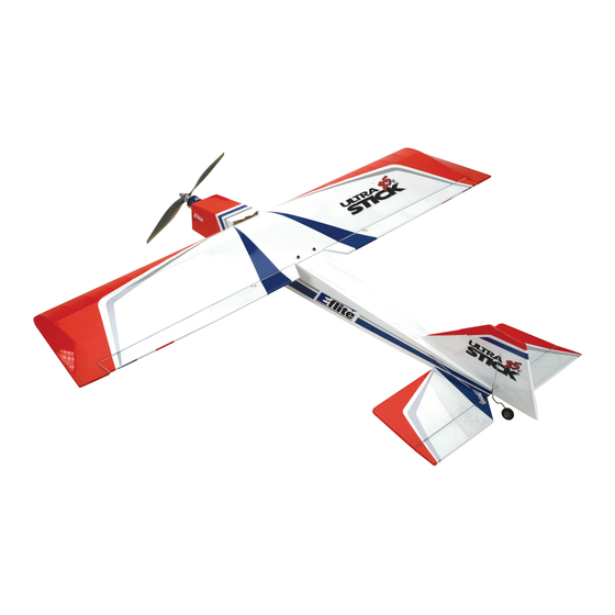
- Page 1 Ultra Stick 25e ® Assembly Manual...
-
Page 2: Table Of Contents
Table of Contents Introduction..............3 Inspection.or.Repairs............9 Specifications..............3 Warranty.Inspection.and.Repairs.........10 Using.the.Manual............3 Non-Warranty.Repairs..........10 Contents.of.Kit/Parts.Layout..........4 Safety,.Precautions,.and.Warnings......11 Required.Radio.Equipment..........5 Landing.Gear.Installation..........12 Optional.Quad.Flaps...........5 Motor.Installation............13 Important.Information.About.Motor.Selection....5 Tail.Installation............16 Sport.Outrunner.Setup..........5 Wing.Preparation............17 Optional.Accessories...........5 Quad.Flap.Modification.(Optional)......21 High.Power.Setup............6 Radio.Installation............25 Warning..............6 Final.Assembly............29... -
Page 3: Introduction
50 in (127cm) Thank you for purchasing the Ultra Stick 25e. Designed Length: 41.5 in (105cm) from the beginning for electric power, the Ultra Stick 25e Wing Area: 480 sq in (31 sq dm) is developed from the popular Hangar 9 ®... -
Page 4: Contents.of.kit/Parts.layout
Contents of Kit/Parts Layout Large Replacement Parts: EFL4026 Wing w/Ailerons EFL4027 Fuselage EFL4028 Tail Set EFL4029 Landing Gear w/Wheels Small Replacement Parts EFL4030 Pushrod Set EFLA213 E-flite/JR/Horizon Decals... -
Page 5: Required.radio.equipment
You will need a minimum 4-channel transmitter, crystals, micro receiver, and four mini servos. You can choose to The Ultra Stick 25e does not include a propeller. We are recommending the Power 25 or Power 32 purchase a complete radio system that includes all of outrunner motors. -
Page 6: High.power.setup
High Power Setup Keep loose items that can get entangled in the propeller away from the prop, including loose clothing, or other EFLM4032A Power 32 BL Outrunner, 770Kv objects such as pencils and screwdrivers. Especially keep CSEPHX45 45-Amp Brushless ESC (depending your hands away from the propeller. -
Page 7: Note.regarding.hinges
Repeat this process for Limited Warranty Period the elevator and rudder. Horizon Hobby, Inc. guarantees this product to be free If however, you find that the hinges pull away, simply from defects in both material and workmanship at the date wick thin CA into the hinge slots and reinstall the hinges/ of purchase. -
Page 8: Limited.warranty.&.Limits.of.liability
(i) repair or (ii) replace, any product THIS WARRANTY IS THE EXCLUSIVE REMEDY OF THE determined by Horizon Hobby, Inc. to be defective. In the CONSUMER. HORIZON HOBBY, INC. SHALL NOT BE event of a defect, these are your exclusive remedies. -
Page 9: Safety.precautions
Ship via a carrier that provides tracking and correctly and avoid damage or injury. insurance for lost or damaged parcels, as Horizon Hobby, Inc. is not responsible for merchandise until it arrives and Questions, Assistance, and Repairs is accepted at our facility. -
Page 10: Warranty.inspection.and.repairs
You will be billed for any return freight for non-warranty repairs. Please advise us of your preferred method of payment. Horizon Hobby accepts money orders and cashiers checks, as well as Visa, MasterCard, American Express, and Discover cards. If you choose to pay by credit card, please include your credit card number and expiration date. -
Page 11: Safety,.Precautions,.And.warnings
Safety, Precautions, and Warnings As the user of this product, you are solely responsible for • Always operate your model in an open area away from operating it in a manner that does not endanger yourself cars, traffic, or people. and others or result in damage to the product or the •... -
Page 12: Landing.gear.installation
Landing Gear Installation 1. Locate the landing gear assembly. Attach the landing gear assembly to the fuselage using Required Parts three 4-40 x 1/2" socket head screws. • Fuselage • Landing gear assembly with wheels • 4-40 x 1/2" socket head screw (3) Required Tools •... -
Page 13: Motor.installation
Motor Installation 1. It may be necessary to attach the motor mount or other accessories to your particular motor at Required Parts this time. • Fuselage • Brushless motor • Brushless speed control • 4-40 x 3/8" socket head screw (4) •... - Page 14 2. Place the four 4-40 blind nuts on the inside of the firewall in the locations for your particular motor. Attach the Outrunner motor to the front of the firewall using four 4-40 x 3/8" socket head screws.
- Page 15 Important Information About Your Brushless ESC 4. Slide the propeller adapter onto the motor. Place the propeller onto the adapter, then a spinner Make sure your ESC brake is programmed to Off. Also, cone onto the adapter and secure. be sure to use an ESC with the proper 9V cutoff when using 3-cell Li-Po packs, and 12V cutoff when using 4-cell Li-Po packs.
-
Page 16: Tail.installation
Tail Installation 1. Slide the rudder into position on the fuselage. The threaded rods extend through the bottom Required Parts of the fuselage. • Fuselage • Rudder/Fin • Stabilizer/Elevator • 3mm locknut (2) • 3mm washer (2) Required Tools and Adhesives •... -
Page 17: Wing.preparation
Wing Preparation 2. Attach the stabilizer using two 3mm washers and two 3mm locknuts. Do not tighten the locknuts all Required Parts the way until after the wing is installed and you • Wing check the alignment. • 6-channel receiver •... - Page 18 1. Install the aileron servo into the wing. 2. Secure the servo using the hardware that was The servo lead will exit the hole in the bottom provided with the servo. center of the wing. Drill a 1/16" (1.5mm) hole through each brass eyelet into the servo mount.
- Page 19 3. Attach the clevis to the 5 " (143mm) 4. Attach the clevis to the control horn. Plug the pushrod wire. Thread the clevis onto the pushrod aileron servo into the receiver and turn on the wire at least 12 turns.
- Page 20 5. Bend the pushrod wire 90 degrees at the 6. Repeat Steps 1 through 5 for the remaining mark made in the last step. Enlarge the outer hole aileron linkage installation. of the servo arm using a 5/64" (2mm) drill bit. Slide the wire through the servo arm.
-
Page 21: Quad.flap.modification.(Optional)
• Drill bit: 1/16" (1.5mm), 5/64" (2mm) • Screwdriver, #0 Phillips • Pliers The Ultra Stick 25e wing is designed with optional quad flaps. The ailerons have been designed with the option of cutting them in half using a hobby knife. Covering has been supplied to cover the cut ends. - Page 22 2. Attach an 18" servo extension to the servo. 3. Attach a clevis onto the 5 " (143mm) pushrod Mount the servo using the same technique wire. Remove the backplate from the control horn described in the previous section. and attach the clevis to the horn.
- Page 23 4. Position the control horn onto the aileron. Match 5. Use a 5/32" (2mm) drill to drill the two holes the fore-aft position of the horn to the one pre- for the control horn mounting screws. Use the installed.
- Page 24 6. Follow the procedure outline in the aileron 7. Use a hobby knife or razor saw to separate the section to mark the pushrod, bend it and attach aileron from the flap. Use the covering provided it to the servo horn. with the model to seal the ends where the two were separated.
-
Page 25: Radio.installation
Radio Installation 1. Install the rudder and elevator servos into the fuselage using the hardware provided with the Required Parts servos. Remember to drill 1/16" (1.5mm) holes • Fuselage into the servo tray for the screws. • Receiver • Servo w/hardware (2) •... - Page 26 Important:.When.using.high-power.servos.or. 2. Plug in the servos and ESC into the receiver. the.Quad.Flap.option,.you.will.need.to.install.a. Mount the receiver to the side of the fuselage receiver.battery.and.switch.harness. using hook and loop material. Route the antenna wire through the bottom of the fuselage to the rear. Note:.Do.not.cut.the.antenna.wire,.as.this.will.
- Page 27 3. Thread a clevis onto the 22 " (572mm) 4. With the radio on, center the servo first. Use pushrod wire for the rudder. Slide the pushrod a felt-tipped pen to mark the pushrod where it into the pushrod tube and attach the clevis to the crosses the servo arm.
- Page 28 5. Bend the pushrod wire at the mark made 6. Repeat Steps 3 through 5 for the elevator in the previous step. Enlarge the hole in the pushrod wire. servo arm using a 5/64" (2mm) drill bit. Secure the pushrod wire to the servo horn using a pushrod connector.
-
Page 29: Final.assembly
Final Assembly Required Parts • Fuselage • Wing • Battery • Battery hatch • 6-32 x 1" socket head bolt (2) • #6 washer (2) • Hook and loop tape • Hook and loop strap Required Tools and Adhesives • Hex wrench: 7/64" ... - Page 30 Note:.Place.a.piece.of.hook.and.loop.tape.on. 4. Plug in the aileron (and flap) servo leads. Slide the.bottom.of.the.battery.and.on.the.fuselage. the wing dowels into the holes at the front. Use where.the.battery.rests..This.will.keep.the. the two 6-32 x 1" socket head screws and two #6 battery.from.shifting.forward.or.backward. washers to secure the wing. during.extreme.maneuvers.
-
Page 31: Control.throws
Control Throws Low Rate High Rate 1. Turn on the transmitter and receiver of your Ultra Stick 25e. Check the movement of the rudder, Ailerons: elevator and ailerons using the transmitter. Up/Down 1/2" (13mm) 7/8" (22mm) Reverse the direction of the servos at the Elevator: transmitter if necessary. -
Page 32: Center.of.gravity
1. Be sure to range check your radio before each The recommended Center of Gravity (CG) location flying session. This is accomplished by turning for the Ultra Stick 25e is 2 " (63.5mm) behind the on your transmitter with the antenna collapsed. -
Page 33: Preflight
Preflight Check Your Radio Note:.Keep.loose.items.that.can.get.entangled. in.the.propeller.away.from.the.prop..These. Before going to the field, be sure that your batteries are include.loose.clothing,.or.other.objects.such.as. fully charged per the instructions included with your radio. pencils.and.screwdrivers..Especially.keep.your. Charge both the transmitter and receiver pack for your hands.away.from.the.propeller. airplane. Use the recommended charger supplied with Double-check that all controls (aileron, elevator, rudder your particular radio system, following the instructions and throttle) move in the correct direction. -
Page 34: Flying.the.ultra.stick.25E
Flying the Ultra Stick 25e You will find the Ultra Stick 25e to be a solid, honest Landing the Ultra Stick 25e is as easy as setting up on sport model. It is capable of handling windy days if you final approach, lowering the throttle to idle and gliding choose. -
Page 35: Flying.the.ultra.stick.25E
Flight times are reduced by about 25% when flying floats cause a pendulum effect on the aircraft during flight, from the water. We hope you enjoy the Ultra Stick 25e as which is common with all models outfitted with floats. Keep much as we do, both on land and water. -
Page 36: 2006 Official Ama National Model Aircraft Safety Code
2006 Official AMA National Model Aircraft Safety Code GENERAL 5) I will not fly my model unless it is identified with my name and address or AMA number on or in the model. 1) I will not fly my model aircraft in sanctioned events, (This does not apply to models while being flown indoors.) air shows or model flying demonstrations until it has been proven to be airworthy by having been previously,... -
Page 37: National.model.aircraft.safety.code
2006 Official AMA National Model Aircraft Safety Code 4) I will operate my model using only radio control 6) For Combat, distance between combat engagement frequencies currently allowed by the Federal line and spectator line will be 500 feet per cubic inch of Communications Commission. -
Page 38: Notes
Notes... -
Page 39: Notes
Notes... - Page 40 ® © 2006 Horizon Hobby, Inc. 4105 Fieldstone Road Champaign, Illinois 61822 (877) 504-0233 horizonhobby.com E-fliteRC.com 8921...