Table of Contents
Advertisement
Quick Links
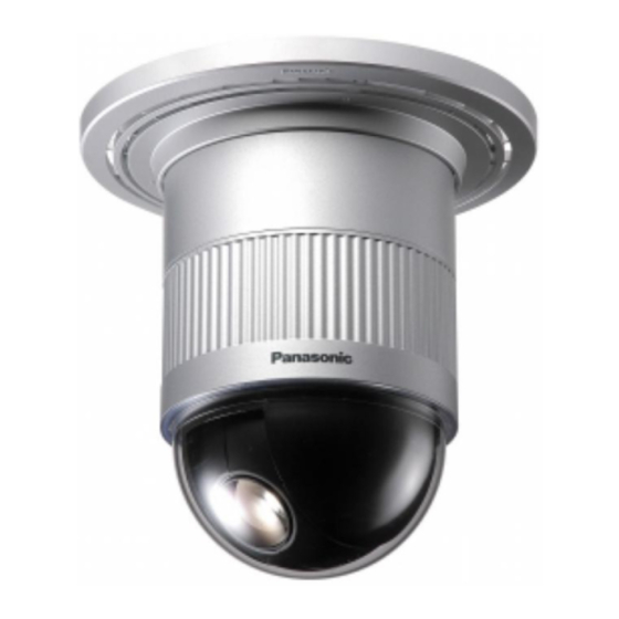
WV-CS850B, WV-CS854BE
SPECIFICATIONS
The Product with PbF
Effective Pixels :
Scanning Area :
Synchronization :
Horizontal Scanning Frequency :
Vertical Scanning Frequency :
Video Output :
Horizontal Resolution :
Vertical Resolution :
Signal-to-Noise Ratio :
Dynamic Range :
Minimum Illumination :
Zoom Speed :
Focus Speed :
Iris :
Maximum Aperture Ratio :
Focal Length :
Angular Field of View :
H :
V :
Electronic Shutter :
AGC :
Sens UP :
Super Dynamic II :
Zoom Ratio :
Iris Range :
Power Source :
752 (H) x 582 (V)
3.65 mm (H) x 2.71 mm (V), 1/4"
Internal/Line-lock / Multiplexed Vertical Drive (VD2)
15.625 kHz
50.00 Hz
1.0 V[p-p] PAL composite/75 Ω
More than 480 lines at centre (C/L, NORMAL), more than 510 lines at centre (C/L, HIGH),
570 lines at centre (B/W)
More than 400 lines at centre
50 dB (AGC OFF, weight on)
48 dB (Super Dynamic II ON)
1 lx (0.1 foot-candle) C/L at SENS UP OFF (AGC HIGH)
0.06 lx (0.006 foot-candle) with PIX SENS UP OFF, B/W, SENS UP OFF (AGC HIGH)
0.03 lx (0.003 foot-candle) with PIX SENS UP B/W at SENS UP OFF (AGC HIGH)
Approx. 4.5 s (TELE/ WIDE) in Manual mode
Approx. 5 s (FAR/NEAR) in Manual mode
Automatic (Open / Close is possible)/Manual
1 : 1.6 (WIDE) - 3.0 (TELE)
3.79 mm - 83.4 mm
2.6° - 52.3°
2.0° - 39.9°
1/50 (OFF), AUTO 1/120, 1/250, 1/500, 1/1 000, 1/2 000, 1/4 000, 1/10 000 s
ON (LOW)/ON (MID)/ON (HIGH)/OFF
MAX 32 times, AUTO/FIX
Selectable ON/OFF (SETUP MENU)
x 22 +Digital Zoom x10
F1.6 - 22, CLOSE
24 V AC, 50 Hz for WV-CS854BE
220 - 240 V AC, 50 Hz for WV-CS850B
Combination Camera
C 2 0 0 3 M a t s u s h i t a E l e c t r i c I n d u s t r i a l C o . , L t d .
A l l r i g h t s r e s e r v e d . U n a u t h o r i z e d c o p y i n g a n d
d i s t r i b u t i o n i s a v i o l a t i o n o f l a w .
ORDER NO. AVS0312524C8
Advertisement
Table of Contents

Related Manuals for Panasonic WV-CS850B


Summary of Contents for Panasonic WV-CS850B
-
Page 1: Specifications
24 V AC, 50 Hz for WV-CS854BE 220 - 240 V AC, 50 Hz for WV-CS850B C 2 0 0 3 M a t s u s h i t a E l e c t r i c I n d u s t r i a l C o . , L t d . - Page 2 8 Lead free solder (Sn - 3.0Ag – 0.5Cu) or equivalents are recommended on repairing our lead free soldered PCB. Power Consumption : 14 W for WV-CS854BE 18 W for WV-CS850B Ambient Operating Temperature : −10°C - +50°C (14°F - 122°F) Dimensions : 120 (D) x 191 (H) mm [4-3/4”...
-
Page 3: Table Of Contents
Power Board for WV-CS850B ........ -
Page 4: Decoration Cover
Camera Mounting Base CONSTRUCTION q Alarm Input Connector u Panning Start Point w Alarm Output Connector i Fall Prevention Wire e Video Output Connector o Decoration Cover r Data Port !0 Dome Cover t Power Cable(WV-CS850B) t*Power Cable(WV-CS854BE) – 1-1 –... -
Page 5: List Of Consumption Parts
LIST OF CONSUMPTION PARTS REF. NO. PART NAME LIFE Pan Motor 2.16 million PRESET actions 2.16 million AUTOPAN revolutions Tilt Motor (19,200 hours as 32 sec per a turn) Cooling Fan 50,000 hours * This is working all the time. Equal to power on time. -
Page 6: Adjustment Procedure
ADJUSTMENT PROCEDURE Extension Board Ass'y A - D(Part No.: V0EA1265AN). 1. Test Equipments Required Extension Cable A for CN201 of the Main Board and The following Test Equipments are required for the Lens as shown in Fig. 1-3. adjustment Combination Camera CS850B/CS854BE. - Page 7 2. Disassembling Procedure E Referring to Fig. 2-1-3, disconnect one connector, and remove three screws that secure the Lower Diecast, and 2.1. Disassembling Procedure for Camera remove the Lower Diecast Case. Head Remove three screws. Q Referring to Fig. 2-1-1, turn the Dome Cover to counter clockwise direction, and remove the Dome Cover.
- Page 8 Y Referring to Fig. 2-1-6, remove two screws that secure O Referring to Fig. 2-1-9, remove four screws that secure the Lens Cover and remove the Lens Cover . the Main Board and remove the Main Board and disconnect one connector. Lens Cover Remove Disconnect...
- Page 9 W Referring to Fig. 2-2-2, remove three screws that secure W Referring to Fig. 2-3-2, remove one screw that secure the the Slip Ring and remove the Slip Ring. Tilt Chassis Ass'y and remove the Tilt Chassis Ass'y from the Camera Unit. Remove three screws.
- Page 10 W Referring to Fig. 2-4-2, remove four screws that secure the Power Bottom Plate and remove the Power Bottom Plate. Remove four screws Power Bottom Plate Fig. 2-4-2 E Referring to Fig. 2-4-3, remove three screws that secure the Insulation Case and remove the Insulation Case. Remove three screws.
- Page 11 Connect Extension Cable C between CN5 of the Servo Board and the Pan Motor and between CN2 of the Servo Board and the Tilt Motor. Connect Extension Cable D between CN1 and CN2 of the Communication Board and the Base Unit. Supply the power to WV-CS850B/CS854BE. Contact the magnet to VS1 on the Servo Board. – 2-7 –...
- Page 12 24V AC Power Supply Power Supply Fig. 3-2-1 (for WV-CS854BE) 220 - 240 V AC (for WV-CS850B) < Switch Setting > Fig. 3-1-1 Referring to Fig. 3-2-2, remove four screws that secure the Upper Cover and remove the Upper Cover.
- Page 13 < Menu Setting > 3.3. Setting Up for Standard Picture The adjustment should be done after 30 minutes warm-up. Set the Mode Selection Switch on the Front Panel to the Set the Logarithmic Gray Scale Chart. "ALARM OFF"(center) position. Incident light of 1 400 lx ± 50 lx on the Logarithmic Gray Keep pressing the Program Switch for 3 seconds or more Scale Chart.
-
Page 14: Camera Adjustment
8 At the prompt, type RADJ2 CS854BE and press the ENTER key, then the initial menu page as shown in Fig. 4- 1-1 will be displayed. PANASONIC EVR ADJUSTMENT SYSTEM (C)MCI Co. CCTV PRODUCT: CS850 EEPROM: 0 ∗∗∗∗∗∗∗∗∗∗∗∗∗∗∗∗∗∗∗∗∗∗∗∗∗∗∗∗∗∗∗∗∗∗∗∗∗∗∗∗∗∗∗∗∗∗∗∗∗∗∗∗∗∗∗∗∗∗∗∗∗∗∗∗ M E N U... - Page 15 Zero-Cross Point AC Line Input Waveform – Video Output Signal Waveform 50 mV ± 10 mV V SYNC 2H ± 4H Fig. 4-1-5 Fig. 4-1-3 8 Press the ENTER key for the next adjustment. 8 Press the ENTER key for the next adjustment. 8 Adjust data with the ARROW keys so that the decay point (7) ALC DC Level Adjustment of V-sync signal gains 2H ±...
- Page 16 NTSC mode PAL mode 135 ± 1 ° dø dø 100% 100% 10° 10° 700 mV ± 50 mV 90 ± 2 ° 0° 0° 10° 10° Fig. 4-1-7 Fig. 4-1-9 8 Press the ENTER key for the next adjustment. 8 Set the Mode Switch of the Vectorscope to "PAL"...
- Page 17 (10.2) White Balance 3200 ˚K Manual Offset B (12.1) 3200 ˚K R Gain Adjustment Adjustment Test Point: Video Output Connector 8 Aim the Camera at the Colour Chip Chart. Test Point: Video Output Connector 8 Aim the Camera at the White Chart or the White Paper. 8 Set the gain control of the Vectorscope to the normal 8 Adjust data with the ARROW key so that the vector position.
- Page 18 8 Press the ENTER key for the next adjustment. (14) Highlight Chroma Clip Adjustment (13.1) 5100 ˚K R Gain Adjustment Test Point: Video Output Connector 8 Connect the terminated Oscilloscope with 75Ω to the Test Point: Video Output Connector Video Output Connector. 8 Aim the Camera at the Colour Chip Chart.
- Page 19 8 At the prompt, type RADJ2 CS85BEAF and press the more than 5˚ ENTER key, then the initial menu page as shown in Fig. 4- 2-1 will be displayed. PANASONIC REMOTE EVR ADJUSTMENT SYSTEM CCTV PRODUCT: CS850 EEPROM: 0 ∗∗∗∗∗∗∗∗∗∗∗∗∗∗∗∗∗∗∗∗∗∗∗∗∗∗∗∗∗∗∗∗∗∗∗∗∗∗∗∗∗∗∗∗∗∗∗∗∗∗∗∗∗∗∗∗∗∗∗∗∗∗∗∗ M E N U...
- Page 20 y After confirming that there is no other object between the 4.3 Tilt Adjustment Camera and the Radiation Chart, press the ENTER key. Note) This tilt adjustment is required in the following cases; u Wait about 40 seconds until finishing the Back Focus 1.
- Page 21 3-3 will be displayed. 8 Type CS854BE.EV2 or xxxxxxxx.EV2 (xxxxxxxx means a file name you named before.) and press the ENTER PANASONIC REMOTE EVR ADJUSTMENT SYSTEM CCTV PRODUCT: CS850 EEPROM: 3 ∗∗∗∗∗∗∗∗∗∗∗∗∗∗∗∗∗∗∗∗∗∗∗∗∗∗∗∗∗∗∗∗∗∗∗∗∗∗∗∗∗∗∗∗∗∗∗∗∗∗∗∗∗∗∗∗∗∗∗∗∗∗∗∗ key.
-
Page 22: Main Board (1/3)
Fig. 4-5-2 appropriate file name for xxxxxxxx within 8 letters, but do not use CS854BE. Then press the ENTER key to finish 8 Supply the Power to the WV-CS850B/CS854BE, and the the adjustment procedure. Camera Head starts panning. 8 If you don't want to save, press the N key, and then press... -
Page 23: Main Board (2/3)
8 Observing the Monitor Screen, adjust the position of the Note: Align the small projection of the Camera Head and the black line on the Upper Plate as shown in Fig. Sensor Section so that the hole on the Bottom Plate 4-5-4. -
Page 24: Servo Board
TXDET F12V Vref TX(B) GND-2 G(NC) TX(A) RX(B) H2– RX(A) POWER BOARD AC 24V for WV-CS854BE AC 220V-240V, MAIN BOARD LENS 50Hz for WV-CS850B CN201 Z-LED+ Z-B– CN300 Z-LED– Z-B+ AGND F-PHOTO-E Z-A+ 1.8V Z-A– AGND OUT– 3.3V AGND F-B+... - Page 25 SCHEMATIC DIAGRAM OF MAIN BOARD (1/3) MAIN BOARD (1/3) <INDEX> MAIN BOARD IC301 L307 OPEN IC303 C332 OPEN R329 FCK2 IC304 C4/D4/C5/D5 IC305 DIG3.3V R320 0 L301 Q203 Q301 R319 L300 Q300 ADO[9] OPEN OPEN OPEN REG2_4.7V ANA6V C343 0.1uF Q302 IC305 L305...
- Page 26 SCHEMATIC DIAGRAM OF MAIN BOARD (2/3) MAIN BOARD (2/3) <INDEX> MAIN BOARD DIG3.3V MA3.3V TD28 DIG3.3V DIG3.3V IC1 E3/F3/G3/E4/F4/G4 IC2 B5/C5/D5/B6/C6/D6 2.2uH 0.1uF 0.1uF IC3 C3 IC4 B3(PAL) TD31 HOLD TD32 HOLD IC5 G5 TD30 TD29 4 Vss 4 Vss IC6 G2 IC7 G6 IC8 E5/F5...
- Page 27 SCHEMATIC DIAGRAM OF MAIN BOARD (3/3) IL BOARD MAIN BOARD (3/3) <INDEX> MAIN BOARD C146 20pF REG5V C112 C2/D2/C3/D3 IC200 IC112 R175 R176 IC201 100k CN400 CN204 A_OUTPUT D_OUTPUT IC202 A-INPUT D-INPUT SVC+ SVC+ IC203 SVC- SVC- A+INPUT D+INPUT IC204 R173 VS901 HVCC...
- Page 28 SCHEMATIC DIAGRAM OF SERVO BOARD (1/2) SERVO BOARD (1/2) <INDEX> SERVO BOARD IC1 D7 PAN_V TILT_V 3.3k 2.4k IC2 D7 PT-SEN5V IC3 E2 IC15 PAN_V C128 IC4 D2 NC_1 NC_9 3.3uF35V NC_2 NC_8 R144 IC6 D3/E3/D4/E4 DAINA 0.01uF MNT0 COMP_IN 0.1uF VDD_2 LPF_OUT...
- Page 29 SCHEMATIC DIAGRAM OF SERVO BOARD (2/2) SERVO BOARD (2/2) <INDEX> SERVO BOARD P[40-47] IC8 A7/A8 IC10 C2/D2 IC16 B3 5V_SADOUT 5V_SADOUT IC18 E3 5V_SAFIELD 5V_SAFIELD 5V_SACLK LOGIC5V IC19 B5/C5 5V_SACLK PAN_GEN PAN_GEN IC20 C7/D7 5V_SADOUT IC21 B6/C6 LOGIC5V IC22 E6/E7 SERVO VIDEO-OUT VIDEO-OUT...
-
Page 30: Sensor Board
SCHEMATIC DIAGRAM OF SENSOR BOARD SENSOR BOARD (CN500) Note: AGND IC502 is not included AGND in Sensor Board Ass’y. AGND R508 OPEN AGND IC502 AGND +V[2] Vfai1 Hfai2 +V[4] Vfai3 Hfai1 +V[1] C504 0.1uF Vfai2A faiRG AGND +V[3] C506 270pF CCDOUT CSUB Vfai2B... - Page 31 SCHEMATIC DIAGRAM OF COMMUNICATION BOARD COMMUNICATION BOARD < INDEX > TD22 TD25 COMMUNICATION BOARD IC309 IC309 IC309 L301 8R2 R331 560 R329 560 R328 560 R330 560 IC302 IC306 R323 TD23 C304 104 L302 8R2 R324 102 B3/B4 IC309 C31 222 IC10 C4/D4 C323 104...
- Page 32 SCHEMATIC DIAGRAM OF POWER BOARD FOR WV-CS850B POWER BOARD POWER TRANSFORMER GND1 L24 2R62 L21 220 GND2 COMMUNICATION BOARD ..CN3 R4 220 OPEN R24 331 220 V - 240 V 50 Hz C21 473 < INDEX >...
- Page 33 SCHEMATIC DIAGRAM OF POWER BOARD FOR WV-CS854BE POWER BOARD VS2 OPEN POWER TRANSFORMER GND1 L21 220 L24 2R62 GND2 COMMUNICATION BOARD ..CN3 R8 112 C10 105 R4 220 AC 24 V OPEN R24 331 C21 104 <...
- Page 34 CONDUCTOR VIEW OF MAIN BOARD MAIN BOARD TILT BOARD (PATTERN SIDE VIEW) <INDEX> <INDEX> MAIN BOARD MAIN BOARD C2/C3/D2/D3 C2/C3/D2/D3 B3 (PAL) B3 (PAL) IC14 IC15 IC14 IC112 IC15 IC200 IC112 IC201 IC200 IC202 IC201 IC203 IC202 IC204 IC203 (COMPONENT SIDE VIEW) IC205 IC204 IC301...
- Page 35 CONDUCTOR VIEW OF SERVO BOARD SERVO BOARD (COMPONENT SIDE VIEW) (PATTERN SIDE VIEW) <INDEX> SERVO BOARD IC16 IC17 IC18 IC19 A6/B6 IC20 IC21 C1/D1 IC22 IC23 IC10 IC25 B5/B6 IC11 A2/B2 IC26 IC12 IC27 IC13 IC28 IC14 B1/B2 IC30 IC15 –...
- Page 36 CONDUCTOR VIEW OF SENSOR BOARD SENSOR BOARD (PATTERN SIDE VIEW) <INDEX> SENSOR BOARD IC500 A2 IC501 B2 IC503 A2 Q500 – 5-3 –...
- Page 37 CONDUCTOR VIEW OF COMMUNICATION BOARD COMMUNICATION BOARD (COMPONENT SIDE VIEW) (PATTERN SIDE VIEW) < INDEX > COMMUNICATION BOARD IC306 IC307 IC308 IC309 IC310 IC311 IC10 IC312 IC11 IC313 IC12 IC314 IC14 IC301 IC302 IC303 IC304 – 5-4 –...
- Page 38 CONDUCTOR VIEW OF POWER BOARD FOR WV-CS850B POWER BOARD POWER BOARD (COMPONENT SIDE VIEW) (PATTERN SIDE VIEW) < INDEX > POWER BOARD – 5-5 –...
- Page 39 CONDUCTOR VIEW OF POWER BOARD FOR WV-CS854BE POWER BOARD (COMPONENT SIDE VIEW) (PATTERN SIDE VIEW) < INDEX > POWER BOARD – 5-6 –...
-
Page 40: Communication Board
Pan Head Tapping Screws PCB6 XYN26+J8FXK Pan Head Screw and Washer Ass'y (Tilt Board) XYN2+J6FN Pan Head Screw and Washer Ass'y PCB3 (Main Board) PCB2 (for WV-CS850B) (Power Board) PCB5 (Sensor Board) Serial No. Label IC502 Serial No. Label Serial No. Label... -
Page 41: Replacement Parts List
Y V9AA2736B4 Tilt Gear Ass'y C0JBAZ001648 Parallel Load 8-bit Shift Register 3PB001770AAA Model No. Label for WV-CS854BE C0JBAR000282 Analog Multiplexers/Demultiplexers 3PB001768AAA Model No. Label for WV-CS850B YWNJM2901VT1 Quad Comparators V4JA1126A4 Earth Spring IC10 C0JBAB000247 Hex Inverters V5EC2400A2 Inner Dome Cover... - Page 42 REF. NO. PART NO. DESCRIPTION REF. NO. PART NO. DESCRIPTION IC306,307 YW78L05UATE2 Voltage Regulator R308 ERJ3GEYJ103V Metal 10K ohms 1/16W IC308,309 C0JBAB000247 Hex Inverters R311-314 ERJ3GEY0R00V Metal 0 ohm 1/16W IC310 C0CBAHC00004 Voltage Regulator R321 ERJ3GEYJ102V Metal 1K ohms 1/16W IC311 C0JBAB000259 Hex Inverters/Buffers...
- Page 43 Ceramic 0.01 µF C10-12 F1H1H222A013 Ceramic 2200 pF F1H1H6R0A243 Ceramic 6 pF C16-18 MCUV1E104ZFV Ceramic 0.1 µF POWER BOARD for WV-CS850B MCUV1E104ZFV Ceramic 0.1 µF YWSK41C106MB Tantalum 10 µF 16V C26-29 MCUV1H102KBV Ceramic 1000 pF PCB2(RTL) VCS85GKY2A Printed Circuit Board Ass'y...
- Page 44 Heat Sink F1J1C105A004 Ceramic 1 µF V4JA1128A4 Clip for IC1 ECKD3D101KBP Ceramic 100 pF F1J1C105A004 Ceramic 1 µF V2PA1286A4 Insulator Sheet for WV-CS850B C15,16 ECA1HHG102 Electrolytic 1000 µF 50V ECQM1103KZ Plastic 0.01 µF MCUV1E104KBN Ceramic 0.1 µF EEUFC1C152 Electrolytic 1500 µF 16V...
- Page 45 REF. NO. PART NO. DESCRIPTION REF. NO. PART NO. DESCRIPTION J0JKB0000004 Beads Inductor Q302 2SD18200WL Transistor G0A2R0H00001 Coil 2 µH Q303 B1HFCFA00003 Transistor Y G4D2A0000022 Power Transformer Q304 B1ADCF000040 Transistor Y XBA2C40ET0A Current Fuse 4 A 250V D2,3 YWHVU359TRF Diode E2,3 K3GE1BB00004 Fuse Holder...
- Page 46 REF. NO. PART NO. DESCRIPTION REF. NO. PART NO. DESCRIPTION R82,83 ERJ2GEJ102X Metal 1K ohms 1/16W R270 ERJ2GE0R00X Metal 0 ohm 1/16W ERJ2GEJ103X Metal 10K ohms 1/16W R271-274 ERJ8GEYJ100 Metal 10 ohms 1/8W R85,86 ERJ2GEJ202 Metal 2K ohms 1/16W R275 ERJ2GEJ152X Metal 1.5K ohms 1/16W...
- Page 47 REF. NO. PART NO. DESCRIPTION REF. NO. PART NO. DESCRIPTION C145 YW36B104K1T Ceramic 0.1 µF YW639AN0518 Coil C146 F1G1H200A408 Ceramic 20 pF ELJFC2R2MF Coil 2.2 µH C147,200 YW36B104K1T Ceramic 0.1 µF L3,4 ELJFC100KF Coil 10 µH C201 YW36B104K1T Ceramic 0.1 µF ELJFC2R2MF Coil 2.2 µH...
- Page 48 REF. NO. PART NO. DESCRIPTION REF. NO. PART NO. DESCRIPTION IC21 C0JBAR000282 Analog Multiplexers/Demultiplexers ERJ2GEJ272X Metal 2.7K ohms 1/16W IC22 C1AB00000358 Controller ERJ2GEJ104X Metal 100K ohms 1/16W IC23 YWTC7S04FUL Inverter ERJ2GEJ122X Metal 1.2K ohms 1/16W IC25 C0DBZFD00011 Series Regulator ERJ2GEJ471X Metal 470 ohms 1/16W IC26...
- Page 49 REF. NO. PART NO. DESCRIPTION REF. NO. PART NO. DESCRIPTION R159 YWR0510P102D Metal 1K ohms 1/16W F1H1C104A042 Ceramic 0.1 µF R160 ERJ2GEJ103X Metal 10K ohms 1/16W F1H1A105A036 Ceramic 1 µF R161 ERJ2GEJ104X Metal 100K ohms 1/16W YW36B104K1T Ceramic 0.1 µF R162 ERJ2GEJ103X Metal...
- Page 50 REF. NO. PART NO. DESCRIPTION REF. NO. PART NO. DESCRIPTION C118 F3G0J6850002 Tantalum 6.8 µF 6.3V SENSOR BOARD C120 YWK235A0R1R Tantalum 0.1 µF 35V C121,122 YWSK41C106MB Tantalum 10 µF 16V Note: C123 YWK235A0R1R Tantalum 0.1 µF 35V C128 ECST1VX335R Tantalum 3.3 µF 35V 8 IC502 (CCD Image Sensor) is not supplied as Printed Circuit Board Ass'y (PCB5).
- Page 51 CS850MLTA Wire Ass'y (Alarm In Cable, Alarm Out Cable) 3TR001738BAA Operating Instractions PE20X35C05B Polyethylene Bag PE26X40C05B Polyethylene Bag V5EA2432A4 Dustproof Sheet V9CT4489BN Packaging Ass'y for WV-CS850B V9CU4489BN Packaging Ass'y for WV-CS854BE V9AA2734A2 Decoration Cover C-903 N N – 7-11 –...