
Related Manuals for Panasonic WV-CS854B


Summary of Contents for Panasonic WV-CS854B
-
Page 1: Operating Instructions
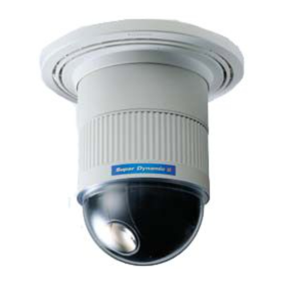
Color CCTV Camera Operating Instructions WV-CS854B Model No. Before attempting to connect or operate this product, please read these instructions carefully and save this manual for future use. - Page 2 You should note the serial number of this unit in the space provided and retain this book as a permanent record of your purchase to aid identification in the event of theft. Model No. WV-CS854B Serial No. For U.S.A For Canada...
-
Page 3: Important Safety Instructions
IMPORTANT SAFETY INSTRUCTIONS 1) Read these instructions. 2) Keep these instructions. 3) Heed all warnings. 4) Follow all instructions. 5) Do not use this apparatus near water. 6) Clean only with dry cloth. 7) Do not block any ventilation openings. Install in accordance with the manufacturer's instructions. 8) Do not use near any heat sources such as radiators, heat registers, stoves, or other apparatus (including amplifiers) that produce heat. -
Page 5: Table Of Contents
PREFACE ... 6 FEATURES ... 6 I Camera Cleaning ... 7 I Preset Data Uploading or Downloading ... 7 PRECAUTIONS ... 7 CONSTRUCTION ... 9 SETUP ... 10 I Setup Menu ... 10 I Setup Menu Description ... 13 SETTING PROCEDURES ... 17 I Menu Display ... -
Page 6: Preface
PREFACE Panasonic presents highly advanced CCTV technology that meets the demands of new and ever-changing applications. This high-performance combination color camera is utilized as a video surveillance device. The camera incorporates Super-Dynamic 2 Digital Signal Processor, pan-tilt mechanism, 22 zoom lens and RS485 communication in a compact enclosure. -
Page 7: I Camera Cleaning
In such cases, activate the refresh mode on the special 2 menu. (See page 42.) To use this camera with WJ-SX550C, WJ-SX150 Matrix Switcher, set the auto cleaning function activated on the Matrix Switcher side, then clean WV-CS854B once a day. I Preset Data Uploading or Down- loading... - Page 8 9. Do not operate the camera beyond the specified temperature, humidity or power source ratings. Do not use the camera in an extreme environment where high temperature or high humidity exists. Do not place the camera near heat sources such as radiators, stoves or other units that produce heat.
-
Page 9: Construction
CONSTRUCTION q Alarm Input Connector w Alarm Output Connector e Video Output Connector r Data Port t Power Cable y Camera Mounting Base u Panning Start Point i Fall Prevention Wire o Decoration Cover !0 Dome Cover... -
Page 10: Setup
SETUP I Setup Menu Setup menus are shown in the diagram below. You can adapt the camera to your requirements by setting up the respective items in these menus. Menus are incorporated in a hierarchical structure, from the setup menu at the top to manual mask area selection at the bottom. - Page 11 Position Setting (P. 18) Preset Identification Setting (P. 20) Light Control Setting (P. 21) Dwell Time Setting (P. 21) Scene File Setting (P. 21) Preset Speed (P. 22) Zone Number Selection (P. 27) Zone Parameter Setting (P. 27) Setting for ON (NESW) (P. 28) Setting for ON (USER) (P.
- Page 12 The keys (switches) to be used for setup are shown in the table below. The joystick on the connected controller may also be used for setup. The table also shows the functions and the operations of the individual controllers. For details, see the manual for the controller to be used.
-
Page 13: I Setup Menu Description
I Setup Menu Description G Presetting (1) Position (POSITION SET) Aligns the camera position and focal point by panning, tilting, zooming and focusing. See page 18 for the setting. (2) Preset Identification (PRESET ID) Assigns the name for preset IDs (identification of up to 16 alphanumeric characters) and can be switched on or off on the monitor screen. - Page 14 (2) Proportional Pan-Tilt Speed (PROPO. P/T) If ON is selected, the pan-tilt speed changes automatically corresponding to the zoom ratio. For example, the pan-tilt speed slows down when the camera zooms in. See page 28 for details. (3) Area Title (AREA TITLE) Up to 8 area titles can be assigned to specific scenes on the DIRECTION (NESW) menu or by alphanumeric (USER) assignment.
- Page 15 Generally, when a light from the background is too strong such as a spotlight, all objects except the main object in the picture are displayed darker because the lens iris is adjusted with respect to strong brightness. This model ignores strong brightness by masking the source of the strong brightness, thereby the main object is displayed clearly.
-
Page 16: Rs485 Communication
(9) Auto Focus (AF MODE) The camera adjusts the focus automatically by sensing the center of the picture. S, M and L stand for the size of the sensing area: Small, Middle and Large. See page 40 for details. MANUAL S, M, L: Auto-focus is activated only when the AF key on the controller is pressed. -
Page 17: Setting Procedures
SETTING PROCEDURES The following setting procedures are described on the assumption that this model is used in combination with WJ-SX550C Matrix Switcher System Controller. In case a controller other than WV- CU550C is used, refer to the table on page 12. I Menu Display G Setup Menu Display WV-CU550C/CJ... -
Page 18: I Preset Menu
I Preset Menu G Preset Menu Display 1. Displaying the preset menu directly (1) Move the cursor to PRESET 1 O and select the position number with the joystick. (2) Press the CAM (SET) key. The preset setting menu appears on the monitor screen. - Page 19 CS654 for example) is incompatible with WV- CS854B’s. WV-CS854B’s preset data will be destroyed if you upload the conventional data. If this happened, reset the WV-CS854B to the default settings. Download the factory settings into the controller and upload the correct preset data newly to the initialized WV-CS854B.
- Page 20 G Preset Identification Setting (PRESET 1. Move the cursor to PRESET ID on the preset setting menu and select ON or OFF with the joystick. The factory default setting is OFF. PRESET NO. 1* POSITION SET PRESET ID ALC/MANUAL DWELL TIME SCENE FILE PRESET SPEED ••••••••|...
- Page 21 To Enter the Next ID without Returning to the Preset Setting Menu (1) In the preset ID setting menu, move the cursor to the top line and select a desired position number with the joystick. (2) Enter, copy, change or delete the ID as described above.
-
Page 22: I Deleting Preset Positions
See the pages below for the settings respectively. Shutter speed: page 36 AGC: page 36 Electronic sensitivity enhancement: page 36 White balance: page 38 Motion detector: page 39 Auto focus: page 40 G Preset Speed Setting (PRESET SPEED) Move the cursor to PRESET SPEED and select a speed with the joystick. -
Page 23: I Home Position Setting (Home Position)
I Home Position Setting (HOME POSITION) 1. To set a position number for the home position Move the cursor to HOME POSITION and select a desired position number with the joystick. 2. Select OFF if you are not using the home position function. - Page 24 This determines the starting point and the cursor moves to END. ** AUTO PAN ** POSITION START SPEED ••••|•••• ENDLESS DWELL TIME PAN LIMIT ZOOM LIMIT (3) Move the joystick to select a panning endpoint and press the CAM (SET) key. This determines the endpoint and the cursor moves to POSITION.
-
Page 25: I Auto Pan Key Setting (Auto Pan Key)
(2) Move the cursor to ZOOM, press the CAM (SET) key, move the joystick to settle the ZOOM position and return to the AUTO PAN menu. The manual zoom operation is not available in the TELE direction beyond position. ** ZOOM LIMIT ** →... - Page 26 G Password Lock (PASSWORD LOCK) Caution: For security, do not operate your VCR for recording while the password menus are displayed on the monitor. A 3-digit number is used for a password to limit access to all settings. 1. Move the cursor to PASSWORD LOCK, then select ON or OFF with the joystick.
-
Page 27: I Special 1 Menu Setting (Special 1)
I Special 1 Menu Setting (SPECIAL 1) G Privacy Zone (PRIVACY ZONE) Up to 8 unwanted zones can be masked on the monitor screen. 1. Move the cursor to PRIVACY ZONE and select ON or OFF with the joystick. Press the CAM (SET) key to display the ZONE NUMBER setting menu. - Page 28 ** ZONE NUMBER 3*/8 ** →PUSH SET PAN/TILT →PUSH SET ZOOM/FOCUS ZONE SCALE ••••|•••• SET DEL Moving the joystick in the L direction decreases the zone frame, and moving it in the H direction increases it. However, the aspect ratio is fixed at 3 to 4.
- Page 29 3. Move the cursor to PUSH SET for ZOOM/FOCUS, and press the CAM (SET) key. ZOOM/FOCUS is highlighted and "U ZOOM D/L FOCUS R" appears. ** DIRECTION(NESW) ** →PUSH SET PAN/TILT →PUSH SET ZOOM/FOCUS POSI U ZOOM D/L FOCUS R 4.
- Page 30 To Quit Editing • To return to the AREA TITLE menu, move the cursor to RET, and press the CAM (SET) key. • To cancel one area title, move the cursor to RESET in the AREA TITLE menu, and press the CAM (SET) key.
- Page 31 3. Open the SET UP menu to stop learning. Notes: • It is recommended to set PAN LIMIT to ON for patrol-learn. Otherwise PAN LIMIT is invalid in playback. • If the power fails in the patrol-learn mode, start the patrol-learn function again from the starting point.
- Page 32 CNT-CLS 1, 2 (Output) Two contact closure signals (Open collector type) are output through the Alarm Output connector. 1. Move the cursor to CNT-CLS 1, and select OFF, ALARM or AUX 1 with the joystick. The factory default setting is OFF. When ALARM is selected, TIME OUT appears.
- Page 33 ON: 10 - fold electronic zoom is available with the ZOOM switch on the controller. OFF: The electronic zoom function is not used. Notes: • A scene magnified by the electronic zoom function may be inferior in picture quality to a non-magnified one.
-
Page 34: I Camera Setting
I Camera Setting G To Display the Camera Setting Menu Move the cursor to CAMERA O, and press the CAM (SET) key. The camera setting menu appears. ** SET UP MENU ** PRESET 1 HOME POSITION SELF RETURN AUTO MODE AUTO PAN KEY AUTO PAN DIGITAL FLIP... - Page 35 G Light Control Setting (ALC/MANUAL) 1. Move the cursor to ALC/MANUAL and select ALC or MANUAL with the joystick. When you select ALC, set backlight compensation. ** SET UP ** CAMERA ID ALC/MANUAL SHUTTER AUTO ON(MID) SENS UP SYNC WHITE BAL ATW1 MOTION DET AF MODE...
- Page 36 6. If you want to change the picture contrast, move the "I" cursor for LEVEL and adjust the level. ** ALC CONT ** BACK LIGHT COMP SUPER-D2 MASK SET LEVEL ••••|•••• 7. Move the cursor to RET and press the CAM (SET) key to return to the CAM SET UP menu.
- Page 37 • When ON is selected for SUPER-D2 on the ALC CONT menu X2 AUTO X4 AUTO X32 AUTO X16 AUTO Notes: • When ON is selected for SUPER-D2 in the ALC CONT menu, FIX is not available for this item. •...
- Page 38 8. Match the vertical phase for both video output signals as closely as possible with the joystick. ** SYNC ** V PHASE COARSE 4(1--16) FINE ••••••|•• ** SYNC ** V PHASE COARSE 1(1--16) FINE •|••••••• Notes: • When the "|" cursor reaches the "+" end, it jumps back to "–".
- Page 39 G Motion Detector (MOTION DET) 1. Move the cursor to MOTION DET and select ON or OFF with the joystick. ** SET UP ** CAMERA ID ALC/MANUAL SHUTTER AUTO ON(MID) SENS UP SYNC WHITE BAL ATW1 MOTION DET AF MODE AUTO L SPECIAL2 2.
- Page 40 Therefore, when this camera is not used in a Panasonic Intelligent CCTV System, select OFF to prevent the above from occurring. G Auto Focus Setting (AF MODE) 1.
- Page 41 NORMAL: Sets the horizontal resolution to more than 480 lines. HIGH: Sets the horizontal resolution to more than 510 lines. Note: After selecting HIGH, noise may increase when the SENS UP function is activated under low illumination. • Digital Noise Reduction (DNR) DNR may be used to improve quality under low light conditions.
- Page 42 • PIX OFF Setting (PIX OFF) In this setting, you can assign a blemish position and compensate the blemish. 1. Move the cursor to PIX OFF and press the CAM (SET) key. The PIX OFF menu appears. ** PIX OFF ** 000 000 2.
-
Page 43: I Rs485 Setup
The initial communication parameters for WV-CS854B are shown on the RS485 setup menu below. Other than the on-screen setup parameters, the 4-bit DIP switch may be used to select 2-line (half duplex) or 4-line (full duplex) communication. -
Page 44: Factory Default Setting
Factory Default Setting Menu Item HOME POSITION TOP MENU SELF RETURN AUTO MODE AUTO PAN KEY DIGITAL FLIP PASSWORD LOCK SPECIAL 1 PRIVACY ZONE PROPO.P/T AREA TITLE PATROL CLEANING EL-ZOOM PRESET ALM IMAGE HOLD TILT ANGLE CAMERA MENU CAMERA ID ALC/MANUAL SUPER-D2 SHUTTER... -
Page 45: Installation
INSTALLATION Precautions • The following steps of installation and connection work should be done by qualified service personnel or system installers and should conform to all local codes. • Be sure to switch the camera off before installation and connection. •... - Page 46 Unit Number Switch 1, an 8-bit DIP switch, specifies the unit number or restores the factory default settings when using the Panasonic protocol. When the switch position corresponding to the unit number 1 - 96* is selected, setting should be made on the RS485 SET UP menu (see page 43).
- Page 47 Unit Switch position number Unit Switch position number -47- Unit Switch position number...
- Page 48 • Defaults are marked with *. • BP stands for Bit Position. • Full duplex is not available in a daisy chain connection. (Panasonic system controllers only) 3. Assemble the Camera Reverse the disassembly procedure. Take care not to cut any cables.
- Page 49 3. Hook the fall prevention wire on the camera mounting base. Be sure to match the wire with the fall prevention wire fixing angle as shown below. Ring of the Fall prevention fall prevention wire fixing angle wire Cautions: • Use the supplied dust protection sheet if the camera mounting base is liable to be exposed to a dusty atmosphere.
-
Page 50: Connections
CONNECTIONS Precautions • The following connections should be made by qualified service personnel or system installers in accordance with all local codes. • See the reverse side of the cover page for main lead connection. 24 V AC Video output Note: When powered up, the unit performs a self-check (including one panning, tilting, zooming and focusing operation). - Page 51 • RS485 Connection Data transmission Data reception Note: Use the cable that is described below for RS485 site communication. • Shielded, twisted pair cable • Low impedance • Wire gauge size is thicker than AWG #22 (0.33 mm • ALARM IN Connections An 8-pin and a 4-pin harness are supplied with the camera as standard accessories.
-
Page 52: System Connections
SYSTEM CONNECTIONS Personal computer RS-232C port Alarm inputs Printer System status monitor ALARM BUSY BACK FORWARD RESET PRESET ZOOM –1CAM +1CAM STOP TELE WIDE Note: When any peripherals are turned off and turned on again, the camera is also turned off and turned back on. Combination camera Matrix switcher... -
Page 53: Specifications
2 outputs (ALARM/AUX1, B/W/AUX2) open collector - output max. 16 V DC Alarm OUT 100 mA OFF (OPEN)/ON (0 V) B/W Mode AUTO/ON/OFF Privacy Zone ON/OFF, up to 8 zones Proportional PAN/TILT ON/OFF Patrol LEARN/PLAY/STOP, up to 60 seconds Cleaning ON/OFF Image Hold ON/OFF WV-CS854B -53-... -
Page 54: Accessories
Panning Range 360 ° endless Panning Angle Setting possible (in auto-pan mode) Panning Mode manual/sequential position/sort position/auto pan manual : approx. 0.1 °/s - 120 °/s 8-steps/64-steps Panning Speed sequence position : maximum approx. 300 °/s Tilting Range 0 ° to 180 ° (–5 ° to 185 ° at 5 ° tilt angle setting) Tilting Mode manual/sequential position/sort position manual : approx. -
Page 55: Appendix
APPENDIX Shortcuts Shortcut operations are available for controllers having the CAM FUNCTION key. Entering from one to three digits with the numeric key(s) and pressing the CAM FUNCTION key will create a shortcut to the respective functions. The CAM FUNCTION key is abbreviated as [CAM FUNC] in the table below. Function Selecting a PRESET position From #1 to #64 AUTO PAN... - Page 56 Unit of Matsushita Electric Corporation of America Security Systems Group www.panasonic.com/cctv Executive Office: One Panasonic Way 3E-7, Secaucus, New Jersey 07094 Zone Office Eastern: One Panasonic Way, Secaucus, NJ 07094 (201) 348-7303 Central: 1707 N.Randal Road, Elgin, IL 60123 (847) 468-5205 Western: 6550 Katella Ave., Cypress, CA 90630 (714) 373-7840...