
Related Manuals for Panasonic WV-CS574E


Summary of Contents for Panasonic WV-CS574E
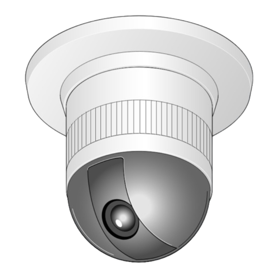
- Page 1 Colour CCTV Camera Operating Instructions WV-CS570 Model Nos. WV-CS574E Before attempting to connect or operate this product, please read these instructions carefully and save this manual for future use.
- Page 2 ENGLISH VERSION We declare under our sole responsibility that the product to which this Vi deklarerar härmed värt fulla ansvar för att den produkt till vilken declaration relates is in conformity with the standards or other denna deklaration hänvisar är överensstämmelse normative documents following the provisions of Directives EEC/73/23 standarddokument, eller andra normativa dokument som framstölls i...
-
Page 3: Important Safety Instructions
IMPORTANT SAFETY INSTRUCTIONS 1) Read these instructions. 2) Keep these instructions. 3) Heed all warnings. 4) Follow all instructions. 5) Do not use this apparatus near water. 6) Clean only with dry cloth. 7) Do not block any ventilation openings. Install in accordance with the manufacturer's instructions. 8) Do not use near any heat sources such as radiators, heat registers, stoves, or other apparatus (including ampli- fiers) that produce heat. -
Page 4: Limitation Of Liability
LIMITATION OF LIABILITY THIS PUBLICATION IS PROVIDED "AS IS" WITHOUT WARRANTY OF ANY KIND, EITHER EXPRESS OR IMPLIED, INCLUDING BUT NOT LIMITED TO, THE IMPLIED WARRANTIES OF MERCHANTABILITY, FITNESS FOR ANY PAR- TICULAR PURPOSE, OR NON-INFRINGEMENT OF THE THIRD PARTY'S RIGHT. THIS PUBLICATION COULD INCLUDE TECHNICAL INACCURACIES OR TYPOGRAPHICAL ERRORS. -
Page 5: Features
The following items are for installation. 4P Alarm Cable ............1 pc. Decorative Cover ........... 1 pc. Connector for 24 V AC (only for WV-CS574E) ..1 pc. Dust Protection Sheet ..........1 pc. OPTIONAL ACCESSORIES Dome Cover (approx. 60 % transparency, smoked type) ..WV-CS2SE Dome Cover (approx. -
Page 6: Precautions
+40 °C {104 °F}, and humidity is below 90 %. or storage. The input power source is 220 V - 240 V AC for WV- CS570 and 24 V AC for WV-CS574E. Do not expose the camera to rain or moisture, nor try to operate it in wet areas. - Page 7 About the Camera Cleaning Function Prolonged use can lead to noise on the monitor and divergence of preset positions. If such conditions persist even after you perform cam- era cleaning (page 41), use the special setup menu to execute the "REFRESH" operation (page 50). If you are using a matrix switcher with a camera clean- ing function (WJ-SX550C), configure the matrix switch- er Auto Cleaning settings so cleaning is performed...
-
Page 8: Table Of Contents
CONTENTS IMPORTANT SAFETY INSTRUCTIONS ................3 LIMITATION OF LIABILITY ....................4 DISCLAIMER OF WARRANTY ..................4 FEATURES ........................5 New DSP for High Sensitivity ..................5 Digital Flip ........................5 Privacy Zone Function ....................5 Patrol Function ......................5 Camera Position Memory ..................5 Motion Detection ...................... -
Page 9: Construction
Decoration Cover t Power Cable for WV-CS570 !0 Dome Cover t* Power Cable for WV-CS574E Ensuring Trouble-free Operation • This camera uses a "slip ring" for transmission of electrical power and signals. A dirty slip ring can cause deterio- ration of picture quality during panning and generation of noise. -
Page 10: Installation Precautions
Panasonic holds absolutely no ed to temperature extremes (Such conditions can responsibility for accidents caused by the camera cause clouding and condensation formation on the falling due to unsuitable installation. -
Page 11: Dip Switch Settings
Important: Heat radiation Before setting up the camera for a configuration The surface of the camera radiates heat. Ventilation where the camera's RS485 data port is used for holes should be provided when installing the camera in camera control (pan, tilt, etc.) by the system con- an enclosed ceiling or confined location where heat can troller, the camera's DIP switches must be con- build up. -
Page 12: Unit Number (Dip Switch 1)
Unit Number (DIP Switch 1) The factory default settings of these DIP switches are all OFF. (Coaxial Multiplex System) Unit Unit Unit DIP Switch 1 DIP Switch 1 DIP Switch 1 Number Number Number 1 ~ 96 * -12-... -
Page 13: Rs485 Communication Parameters (Dip Switch 1)
Unit Unit Unit DIP Switch 1 DIP Switch 1 DIP Switch 1 Number Number Number * When using the Unit Number 1 to 96 setting, the unit number setting needs to be configured using the RS485 SET UP menu. For details about configuring this setting, see step 2 and page 19. * Turning on power when this setting is selected causes the RS485 SET UP menu to appear during the initialization routine. -
Page 14: Camera Installation
CAMERA INSTALLATION Preparing the Camera and Fixing screw Decorative Cover for Side Cable Exit After loosening the screw, press The camera and decorative cover should be prepared upwards on the as shown below when mounting the camera on a ceil- camera and then ing or wall with its cables (power, video output, RS485, remove it. - Page 15 5. Hook the fall prevention wire on the camera mount- 7. Tighten the fixing screw M3 (provided). ing base. Notes: (1) Tighten the camera fixing screw with a screw- driver. (2) Follow the instructions given here to ensure that the camera and camera mounting base are installed safely.
-
Page 16: Uninstalling The Camera
UNINSTALLING THE CAMERA Caution: Make sure you perform the steps below carefully and exactly when uninstalling the camera and deco- rative cover. Failure to do so creates the risk of dam- age to the camera. Uninstalling the Camera The camera and its base unit are secured by screws. This configuration provides double anchoring, and you should use the following procedure to uninstall the cam- era. -
Page 17: Connections
• See the reverse side of the cover page for main lead connection. 220 V - 240 V AC (WV-CS570) 24 V AC cable 24 V AC (WV-CS574E) RS485 cable Data port Coaxial cable To VIDEO IN... - Page 18 • RS485 Connection T (B) Data transmission Orange T (A) Yellow R (B) Data reception Green R (A) Note: Alarm OUT (4-pin) Use the cable that is described below for RS485 site Wire colour Function communication. Grey OUT 1 • Shielded, twisted pair cable •...
-
Page 19: Rs485 Setup
RS485 SETUP Use the following procedure to configure the RS485 8. Move the cursor to WAIT TIME, and then tilt the joy- setup when you want to use the system controller to stick left or right to select a wait time setting. control the camera (pan, tilt, etc.) via the camera's data The wait time is the time that the camera should wait port. -
Page 20: Using The Setup Menu
USING THE SETUP MENU Setup Menu Setup menus are shown in the diagram below. You can adapt the camera to your requirements by setting up the respective items in these menus. Menus are incorporated in a hierarchical structure, from the setup menu at the top to manual mask area selection at the bottom. - Page 21 Position Setting (P. 27) Preset ID Editing (P. 27) Manual Level Adjustment Preset Identification Setting BLC OFF (P. 44) (Contrast) (P. 44) (P. 28) Manual Mask Area Selection BLC ON (P. 43) Light Control Setting (P. 29) (P. 44) Manual Iris Adjustment (P. 43) Dwell Time Setting (P.
-
Page 22: Setup Menu Description
Setup Menu Description SQ: Starts the sequence function. SR: Starts the sort function. Presetting PT: Starts the patrol function. (1) Position (POSITION SET) See page 31 for the setting. Aligns the camera position and focal point by pan- ning, tilting, zooming and focusing. Auto Mode (AUTO MODE) See page 27 for the setting. - Page 23 Special 1 Menu • Positioning is completed at the HOME position in the SELF RETURN mode. (1) Privacy Zone (PRIVACY ZONE) • Positioning is completed in the ALARM IN mode. This setting is used for masking unwanted zones, • When positioning to the starting point is completed hiding them from display on the monitor screen.
- Page 24 • ALC Mode with BLC OFF (6) Synchronization (SYNC) In this mode, the picture is divided into 48 areas. If You can select the internal sync (INT) mode or the there is a source of brightness that interferes with line-lock sync (LL) mode. Additionally, this model the clarity of the picture in these masks, correspon- accepts the VD2 signal from a specified component.
- Page 25 (9) Auto Focus (AF MODE) The camera adjusts the focus automatically by sens- ing the centre of the picture. S, M and L stand for the size of the sensing area: Small, Middle and Large. See page 48 for details. MANUAL S, M, L: Auto-focus is activated only when the button that is assigned for the auto-focus function on the controller is pressed.
-
Page 26: Setting Procedures
SETTING PROCEDURES The following setting procedures are described on the Preset Menu assumption that this model is used in combination with Preset Menu Display WJ-SX150 Matrix Switcher and WV-CU650 System 1. Displaying the preset menu directly Controller. (1) Move the cursor to PRESET 1 O and select the position number with the joystick. - Page 27 Notes: 3. Pan Offset • The * mark indicates that the position number If the camera is replaced with a new one, the pan has been preset. offset function is used to adjust its positions to be • The character H refers to the home position. the same as before except patrol setting.
- Page 28 4. To Set the Lens Zoom and Focus Positions Preset Identification Setting (PRESET (1) Move the cursor to PUSH SET for ZOOM/FOCUS and press the CAM (SET) button. The ZOOM/ 1. Move the cursor to PRESET ID on the preset setting FOCUS setting menu appears.
- Page 29 (2) Display the most prospective ID. (3) Follow the step "To Change an Entered Preset ID" if necessary. To Change an Entered Preset ID (1) Move the pointer to the character to be edited in the editing area with the joystick. FLOOR 1 DOOR (2) Select a new character with the joystick.
- Page 30 See the pages below for the settings respectively. ** MANUAL CONT ** Shutter speed: page 44 IRIS ••••|•••• AGC: page 45 CLOSE OPEN Electronic sensitivity enhancement: page 45 White balance: page 46 Motion detector: page 47 Auto focus: page 48 Preset Speed Setting (PRESET Dwell Time (DWELL TIME) SPEED)
-
Page 31: Deleting Preset Positions
Deleting Preset Positions Home Position Setting (HOME 1. Move the cursor to PRESET 1 and select the position POSITION) number to be deleted with the joystick. 1. To set a position number for the home position Move the cursor to HOME POSITION and select a ** SET UP MENU ** desired position number with the joystick. -
Page 32: Auto Mode Selection (Auto Mode)
Auto Mode Selection (AUTO This determines the starting point and the cursor moves to END. MODE) 1. To set auto mode ** AUTO PAN ** Move the cursor to AUTO MODE and select a mode POSITION START with the joystick. Modes change as follows: SPEED ••••|••••... -
Page 33: Auto Pan Key Setting (Auto Pan Key)
OFF: The camera pans from the starting point to the (2) Move the cursor to ZOOM, press the CAM (SET) endpoint, and rotates backward to the starting button, move the joystick to settle the ZOOM point. position and return to the AUTO PAN menu. The This movement is repeated over and over. -
Page 34: Digital Flip Setting (Digital Flip)
AUTO PAN: Assigns the auto panning function to Password Lock (PASSWORD LOCK) the button. Caution: SEQ: Assigns the SEQUENCE function to the but- For security, do not operate your VTR for recording ton. while the password menus are displayed on the SORT: Assigns the SORT function to the button. -
Page 35: Special 1 Menu Setting (Special 1)
3-4 To cancel an incomplete password, move the Special 1 Menu Setting cursor to RESET, and press the CAM (SET) but- (SPECIAL 1) ton. The screen returns to the verification menu. Privacy Zone (PRIVACY ZONE) 3-5 To return to the SET UP MENU menu without ver- ifying the password, move the cursor to RET, and Up to 8 unwanted zones can be masked on the monitor press the CAM (SET) button. - Page 36 • When 5 privacy zones or more are framed on the ** ZONE NUMBER 3*/8 ** →PUSH SET PAN/TILT displayed screen in the same time, the whole screen →PUSH SET ZOOM/FOCUS will be masked. In this case, diminish the number of the zones and set the privacy zones larger.
- Page 37 Area Title (AREA TITLE) 3. Move the cursor to PUSH SET for ZOOM/FOCUS, and press the CAM (SET) button. ZOOM/FOCUS is Up to 8 area titles can be added in specific positions. highlighted and "U ZOOM D/L FOCUS R" appears. 1.
- Page 38 To Quit Editing ** AREA TITLE(USER) ** NORTH • To return to the AREA TITLE menu, move the cursor to RET, and press the CAM (SET) button. EAST SOUTH-EAST • To cancel one area title, move the cursor to RESET SOUTH SOUTH-WEST in the AREA TITLE menu, and press the CAM (SET)
- Page 39 • DIGITAL FLIP 2. Operate patrol-learn manually. • PRIVACY ZONE 3. Open the SET UP menu to stop learning. • CAMERA ID Notes: • PROPO.PT • It is recommended to set PAN LIMIT to ON for • PAN LIMIT patrol-learn. Otherwise PAN LIMIT is invalid in •...
- Page 40 Alarm Input/Output (ALARM IN/OUT) CNT-CLS 1, 2 (Output) Two contact closure signals (Open collector type) are Move the cursor to ALARM IN/OUT, and press the CAM output through the Alarm Output connector. (SET) button. The ALARM IN/OUT submenu appears. 1. Move the cursor to CNT-CLS 1, and select OFF, ** SPECIAL 1 ** ALARM or AUX 1 with the joystick.
- Page 41 Cleaning (CLEANING) ON: 10 - fold electronic zoom is available with the ZOOM switch on the controller. With CLEANING in the ON position, the camera’s built- OFF: The electronic zoom function is not used. in electromechanical contacts are cleaned at regular Notes: intervals (approx.
-
Page 42: Camera Setting
Image Hold (IMAGE HOLD) Camera Setting The camera picture remains as a still image on the To Display the Camera Setting Menu monitor screen until the camera reaches the preset Move the cursor to CAMERA O, and press the CAM position. - Page 43 Light Control Setting (ALC/MANUAL) CAMERA ID 0123456789 1. Move the cursor to ALC/MANUAL and select ALC or ABCDEFGHIJKLM NOPQRSTUVWXYZ MANUAL with the joystick. When you select ALC, ().,'":;&#!?= +-*/%$ÄÜÖÆÑÅ set backlight compensation. SPACE POSI RET RESET ** SET UP ** CAM1....
- Page 44 (2) ALC Mode with BLC OFF 6. If you want to change the picture contrast, move the 1. Move the cursor to BLC and select OFF. (When you "I" cursor for LEVEL and adjust the level. select MANUAL, BLC is not available.) MASK SET Note: appears on the menu.
- Page 45 • In the AUTO mode, an object is clearly imaged Synchronization (SYNC) under highlighted conditions by using the combina- Move the cursor to SYNC and select LL or INT with the tion technology of iris and shutter functions. joystick. Note: When the selected shutter speed caused flicker ** SET UP ** on condition that fluorescent lamps stay on,...
- Page 46 5. Move the cursor to COARSE with the joystick. Notes: • When the "|" cursor reaches the "+" end, it jumps back to "–". At the same time, COARSE is incre- ** SYNC ** mented by one step to enable a continuous V PHASE adjustment.
- Page 47 (2) Automatic White Balance Control Mode (AWC) 3. Move the cursor to MASK SET and press the CAM 1. Move the cursor to WHITE BAL and select AWC → (SET) button. 48 mask areas appear on the monitor PUSH SET with the joystick. screen.
- Page 48 3. Bright objects or high intensity objects. Therefore, when this camera is not used in a 4. Single colour object such as a white wall or fine Panasonic Intelligent CCTV System, select OFF to felt prevent the above from occurring.
- Page 49 Special 2 Menu (SPECIAL2) NORMAL: Sets the horizontal resolution to more than 480 lines. This menu lets you adjust and set up the picture quality HIGH: Sets the horizontal resolution to more than to meet your requirements. 510 lines. Move the cursor to SPECIAL2 and press the F3 button Note: of WV-CU650.
- Page 50 After a blemish compensation position is set up, (*) The camera is reset to the factory default settings. is attached at the right of the number. (However, the edited settings for PRESET MENU, AUTO PAN, PATROL (SPECIAL 1), PIX OFF (SPECIAL 2) and 3.
- Page 51 Factory Default Setting Menu Item Setting Menu Item Setting HOME POSITION PRESET ID TOP MENU PRESET MENU SELF RETURN ALC/MANUAL AUTO MODE AUTO PAN KEY AUTO PAN DWELL TIME DIGITAL FLIP SCENE FILE PASSWORD LOCK PRESET SPEED • • • • • • • • SPECIAL 1 PRIVACY ZONE SCENE FILE...
-
Page 52: Specifications
SPECIFICATIONS WV-CS574E WV-CS570 Effective Pixels 752 (H) x 582 (V) Scanning Area 3.65 mm (H) x 2.71 mm (V), 1/4 in. Synchronization internal/line-lock / multiplexed vertical drive (VD2) Horizontal Scanning 15.625 kHz Frequency Vertical Scanning 50.00 Hz Frequency 1.0 V[P-P] PAL composite/75 Ω... - Page 53 Panning Range 360 ° endless Panning Angle Setting possible (in auto-pan mode) Panning Mode manual/sequential position/sort position/auto pan manual : approx. 0.1 °/s - 120 °/s 8-steps/16-steps/64-steps Panning Speed sequence position : maximum approx. 300 °/s Tilting Range 0 ° to 180 ° (–5 ° to 185 ° at 5 ° tilt angle setting) Tilting Mode manual/sequential position/sort position manual : approx.
-
Page 54: Shortcuts
SHORTCUTS Shortcuts are supported when you are using the system controller that has a CAM FUNCTION button. With shortcuts, you can configure camera functions by inputting function codes on the 10-key pad and then pressing the CAM FUNCTION button. The following is a list of all of the shortcuts that are supported by this camera. In addition, you can also move the cam- era to a preset position by inputting the applicable position number on the 10-key pad. - Page 55 Controller Operation Setting [1] + [7] + [0] + [CAM FUNCTION] IRIS: CLOSE [1] + [7] + [1] + [CAM FUNCTION] SHUTTER: ON [1] + [7] + [2] + [CAM FUNCTION] SHUTTER: OFF [1] + [7] + [3] + [CAM FUNCTION] Increases shutter speed one step.
-
Page 56: Troubleshooting
TROUBLESHOOTING Before requesting service, check the following symptoms to see if you can solve the problem yourself. If the countermeasures described below do not correct the problem, or if the symptoms you are experiencing are not covered here, contact a quality service person or system installer. Cause and Recommended Action Reference Pages Problem... - Page 57 Cause and Recommended Action Reference Pages Problem Afterimages in the picture • Check the DNR setting. • Use the PIX OFF function to perform blemish com- White specks in the picture pensation. • Is the camera connected correctly? See the operat- ing instructions that come with the system controller –...
- Page 58 Cause and Recommended Action Reference Pages Problem Picture is different from the • Adjust the picture using the preset menu and a position setting. scene file. Upper part of the picture is • This is caused by the camera's internal cover. It black when the camera is in a –...
- Page 60 Matsushita Electric Industrial Co., Ltd. Osaka, Japan http://www.panasonic.co.jp/global/ Printed in Japan Gedruckt in Japan Imprimé au Japon Impreso en Japón Stampato in Giappone © 2005 Matsushita Electric Industrial Co., Ltd. All Rights Reserved. N0405-1055 3TR003480BAA ç‡Ô˜‡Ú‡ÌÓ ‚ üÔÓÌËË...