
Related Manuals for Panasonic WV-CS320


Summary of Contents for Panasonic WV-CS320
- Page 1 Colour CCTV Camera Operating Instructions WV-CS320 Model No. WV-CS324E Before attempting to connect or operate this product, please read these instructions carefully and save this manual for future use.
- Page 2 ON-OFF switches has power supplied to the unit whenever the power cord is inserted into Model No. WV-CS320/324E the power source; however, the unit is opera- tional only when the ON-OFF switch is in the Serial No.
-
Page 3: Table Of Contents
CONTENTS PREFACE ........................4 FEATURES ......................... 4 Camera Cleaning ....................4 Preset Data Uploading or Downloading ............. 4 PRECAUTIONS ......................5 CONSTRUCTION ...................... 7 SETUP ........................8 Setup Menu ......................8 Setup Menu Description ..................11 SETTING PROCEDURES ................... 14 Menu Display ...................... -
Page 4: Preface
Note: Take notice of the following cases when uploading the downloaded data to the camera. • Preset positions may vary. If a preset position varies, delete the preset position and set the cor- rect preset position newly. • You cannot exchange the preset data between WV-CS320 and other models. -
Page 5: Precautions
90 %. personnel for servicing. The input power source is 220 V to 240 V AC for WV-CS320 and 24 V AC for WV-CS324E. 4. Do not use strong or abrasive detergents when cleaning the camera body. 9. Do not install the camera near the air out- Use a dry cloth to clean the camera when it let of an air conditioner. - Page 6 11. Do not aim the camera at the same object for a long time. Burn-in of an image may be caused on the fluorescent screen of CRT. • Matsushita Electric Industrial Co., Ltd. here- with declares that it will not be liable for any damage, whether direct or indirect, caused by using the product for business transac- tion or security, or malfunctioning of this...
-
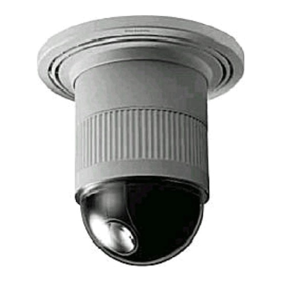
Page 7: Construction
CONSTRUCTION (WV-CS320) (WV-CS324E) q Video Output Connector t Panning Starting Point w Power Cable for WV-CS320 y Fall Prevention Wire e* Power Cable for WV-CS324E u Decoration Cover r Camera Mounting Base i Dome Cover... -
Page 8: Setup
SETUP Setup Menu Setup menus are shown in the diagram below. Various kinds of setup are available to have the camera fulfill your requirements. Menus are built in a hierarchical structure from the Setup menu at the top to Manual Mask Area Selection at the bottom. These menus are described in the following pages for reference prior to setup. - Page 9 The keys (switches) to use for setup are shown in the table below. The joystick on the connected con- troller may also be used for setup. The table also shows the functions versus the operations of the individ- ual controllers. For details, see the manual for the controller to be used. The switches and controls are abbreviated as SW and CTRL respectively in the table.
-
Page 10: Setup Menu Description
Setup Menu Description Presetting (1) Position (POSITION SET) Aligns the camera position and focal point by panning, tilting, zooming and focusing. See page 15 for the setting. (2) Preset Identification (PRESET ID) Assigns the name for preset IDs (identification of up to 16 alphanumeric characters) and can be switched on or off on the monitor screen. - Page 11 FLIP-A-CHIP FLIP-A-CHIP is for setting the movement of the camera by using the joystick. See page 22 for the setting. Cleaning (CLEANING) This is used for refreshing the electro-mechanical contacts built into the camera. Use this function for maintenance when the camera has been directed at a specific spot or panned over a specific range for a long time.
- Page 12 (4) Gain Control (AGC) You can set the gain (brightness level portion of an image) to automatic level adjustment ON (LOW, MID, HIGH) or fixed level (OFF). See page 26 for the setting. (5) Synchronization (SYNC) You can select the internal sync (INT) mode or the line-lock sync (LL) mode. Additionally, this model accepts the VD2 signal (multiplexed vertical drive signal with the composite video output signal) from a specified component.
-
Page 13: Setting Procedures
SETTING PROCEDURES The following setting procedures are described on the assumption that this model is used in combination with the WJ-SX550C Matrix Switcher and WV-CU550CJ System Controller. In case a controller other than the WV-CU550CJ is used, refer to the table on page 10. Menu Display D4 menu Setup Menu Display... -
Page 14: Presetting
Setup menu Presetting ** SET UP MENU ** Preset Menu Display PRESET HOME POSITION OFF 1. Displaying the preset menu directly SELF RETURN (1) Move the cursor to PRESET 1 O and select the position num- AUTO MODE FLIP-A-CHIP CLEANING ber by moving the joystick to the right or left. - Page 15 Notes: Position setting menu • When the camera is used at a nearly horizontal angle, the PRESET NO. 1 focus may not be adjustable to a high level of accuracy. POSITION SET PRESET ID • If you move the cursor to the position number and move the ALC/MANUAL AF MODE MANUAL...
- Page 16 To Enter a New Preset ID Preset ID setting menu (1) Move the cursor to the desired character using the joy- Character Cursor stick, and press the CAM (SET) key. (2) The selected character appears in the editing area. PRESET NO. 1 0123456789 (The pointer in the editing area moves to the right auto- ABCDEFGHIJKLM...
- Page 17 To Enter the Next ID without Returning to the Preset Setting PRESET NO. 1* Menu 0123456789 ABCDEFGHIJKLM (1) In the preset ID setting menu, move the cursor to the top line NOPQRSTUVWXYZ ().,'":;&#!?= and select a desired position number by moving the joystick +-*/%$ÄÜÖÆÑÅ...
-
Page 18: Deleting Preset Positions
Setup menu Deleting Preset Positions ** SET UP MENU ** 1. Move the cursor to PRESET 1 and select the position number to PRESET be deleted by using the joystick. HOME POSITION OFF SELF RETURN AUTO MODE FLIP-A-CHIP CLEANING IMAGE HOLD CAMERA 2. -
Page 19: Auto Mode Selection (Auto Mode)
Setup menu Auto Mode Selection (AUTO MODE) ** SET UP MENU ** 1. To set auto mode PRESET Move the cursor to AUTO MODE and select a mode by moving HOME POSITION OFF SELF RETURN the joystick to the right or left. AUTO MODE AUTO PAN FLIP-A-CHIP... - Page 20 5. To set pan limit ON/OFF Endpoint Move the cursor to PAN LIMIT and select ON or OFF by Camera moving the joystick to the right or left. Start-end Self-end The factory default setting is OFF. range of range of auto pan pan limit ON: Manual pan is limited from the starting point to the end-...
-
Page 21: Flip-A-Chip Setting
Flip-A-Chip Setting Setup menu Move the cursor to FLIP-A-CHIP and select ON or OFF by moving the ** SET UP MENU ** joystick to the right or left. PRESET The factory default setting is OFF. HOME POSITION OFF SELF RETURN OFF: Tilt range is limited from 0 °... -
Page 22: Image Hold (Image Hold)
Setup menu Image Hold (IMAGE HOLD) ** SET UP MENU ** The camera picture remains as a still image on the monitor screen PRESET until the camera reaches the preset position. This function is useful for HOME POSITION OFF SELF RETURN surveillance via a local area network. - Page 23 Camera setting menu Light Control Setting (ALC/MANUAL) ** SET UP ** 1. Display the SET UP menu on the monitor screen by referring to CAMERA ID page 14. ALC/MANUAL SHUTTER 2. Move the cursor to ALC/MANUAL and select ALC or MANUAL by ON(MID) SYNC using the joystick.
- Page 24 (2) ALC Mode with BLC OFF Blinking 1. Move the cursor to the BLC and select OFF. When you select MANUAL, BLC is not available. The MASK SET appears on the menu. 2. Move the cursor to MASK SET and press the CAM (SET) key. The 48 mask areas appear on the monitor screen.
- Page 25 Shutter Speed Setting (SHUTTER) Move the cursor to SHUTTER and select the electronic shutter speed Camera setting menu by using the joystick. The factory default setting is OFF. ** SET UP ** The electronic shutter speed changes as follows by using the joystick: CAMERA ID ALC/MANUAL SHUTTER...
- Page 26 5. Move the cursor to COARSE by using the joystick. SYNC menu ** SYNC ** V PHASE COARSE 1(1--16) 6. Match the vertical phases for both video output signals as closely FINE •|••••••• as possible by using the joystick. The coarse adjustment can be incremented in steps of 22.5 degrees (16 steps) with the joystick.
- Page 27 Notes: ** SYNC ** • When the “|” cursor reaches the “+” end, it jumps back to “–”. V PHASE At the same time, COARSE is incremented by one step to COARSE 4(1--16) enable a continuous adjustment. The reverse takes place FINE ••••••|••...
- Page 28 3. PUSH SW returns to normal when balance setting is completed. AWC fine adjustment menu 4. For fine adjustment of the AWC, move the cursor to AWC and ••••|•••• press the CAM (SET) key. The AWC fine adjustment menu ••••|•••• appears on the monitor screen.
- Page 29 Camera setting menu Special Menu (SPECIAL) This menu lets you adjust and set up the picture quality to meet your ** SET UP ** CAMERA ID requirements. ALC/MANUAL SHUTTER • Move the cursor to SPECIAL and press the F2 button of the WV- ON(MID) SYNC CU550CJ.
- Page 30 (6) Digital Noise Reduction (DNR) ** SPECIAL ** DNR may be used to improve quality under low light conditions. CHROMA GAIN •••• •••• AP GAIN ••• ••••• There are 2 levels of DNR, which may be selected depending on PEDESTAL •••...
-
Page 31: Installation
INSTALLATION Precautions • The following steps of installation and connection work should be done by qualified service person- nel or system installers and should conform to all local codes. • Be sure to switch the camera off before installation and connection. •... - Page 32 1. Mark the mounting holes on the ceiling, Cautions: using the removed camera mounting base • Use the supplied dust protection sheet if the as a template. camera mounting base is liable to be exposed to a dusty atmosphere. Remove the cover from the dust protection sheet, then stick the sheet on the camera mounting base.
- Page 33 5. Tighten the fixing screw M3 (provided). b. Top Cable Exit Notes: Push the decoration cover against the cam- (1) Tighten the camera fixing screw with a era mounting base. screwdriver. (2) Follow the instructions given here to ensure that the camera and camera mounting base are installed safely.
-
Page 34: Connections
• The following connections should be made by qualified service personnel or system installers in accordance with all local codes. • See the reverse side of the cover page for mains lead connection. 220 V to 240 V AC (WV-CS320) 24 V AC cable 24 V AC (WV-CS324E) -
Page 35: Prevention Of Blooming And Smear
Therefore, the camera should be operated carefully in the vicinity of extremely bright objects to avoid smear or blooming. SPECIFICATIONS WV-CS320 WV-CS324E Effective pixels 752 (H) x 582 (V) Scanning area 3.65 mm (H) x 2.71 mm (V), 1/4”... -
Page 36: Accessories
Auto focus MANUAL/AUTO Auto mode OFF/AUTO PAN Flip-A-Chip ON/OFF Camera ID preset ID, camera ID, characters ON/OFF Cleaning ON/OFF Panning range 360 ° endless Panning angle setting possible (in auto-pan mode) Panning mode manual/auto pan manual : approx. 1.0 °/s to 100 °/s, 8-steps/64-steps Panning speed preset position : maximum approx. -
Page 37: Appendix
APPENDIX Shortcuts Shortcut operations are available to controllers having the CAM FUNCTION key. Entering from one to three digits using the numeric key(s) and pressing the CAM FUNCTION key will create a shortcut to the respective functions. The CAM FUNCTION key is abbreviated as [CAM FUNC] in the table below. Function Function Selecting a PRESET position From #1 to #10... - Page 38 Matsushita Electric Industrial Co., Ltd. Web Site : http://www.panasonic.co.jp/global/ N0702-1092 3TR001208BAA Printed in Japan Gedruckt in Japan Imprimé au Japon Impreso en Japón Stampato in Giappone 2002 © Matsushita Communication Industrial Co., Ltd. All rights reserved.