Table of Contents
Advertisement
Advertisement
Table of Contents

Related Manuals for JRC JMA-3910-4


Summary of Contents for JRC JMA-3910-4
-
Page 3: Preface
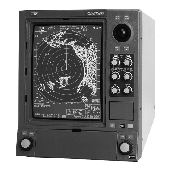
PREFACE Thank you very much for purchasing the JRC marine radar equipment, JMA-3910-4/6 and JMA-3925-6/7/9. This equipment is a marine radar equipment designed to obtain safe operation of marine ships. The equipment consists of a radar signal transceiver unit, a CRT display unit and a scanner unit as its main units. -
Page 4: Before Operation
Before Operation Pictorial Indication Various pictorial indications are included in this manual and are shown on these equipment so that you can operate them safely and correctly and prevent any danger to you and / or to other persons and any damage to your property during operation. Such indications and their meanings are as follows. -
Page 5: Cautions To Be Used During Operation
Cautions to be Used During Operation WARNING Do not touch the insides of the scanner unit, transceiver and display unit. Touching any high voltage area, you will get an electric shock. For maintenance, inspection and adjustment of internal parts of these equipment, consult with our sales office or distributor in your district. -
Page 6: Precautions Before Operation
NNNN NNNN PRECAUTIONS BEFORE OPERATION Cautions for high voltage High voltages from hundreds volts to tens of thousands volts are to be applied to the electronic equipment such radio and radar devices. You do not face any danger during normal operation, but sufficient cares are required for maintenance, inspection and adjustment of their internal components. -
Page 7: First Aid Treatments
NNNNNNNNN NNNNNNNNN FIRST AID TREATMENTS ✩ First-aid treatments As far as the victim of electric shock is not in dangerous condition, do not move him and practice artificial respiration on him immediately. Once started, it should be continued rhythmically. (1) Do not touch the victim confusedly as a result of the accident, but the rescuer may also get an electric shock. -
Page 8: When Pulse Is Beating But Breathing Has Stopped
✩ When pulse is beating but breathing has stopped (1) Tilt the victim’s head back as far as this face looks back. (A pillow may be inserted under his neck.) (2) Push his jaw upward to open his throat wide (to spread his airway). (3) Pinch the victim’s nostrils and take a deep breath, block his mouth completely with yours and blow into his mouth strongly. -
Page 9: When Both Pulse And Breathing Have Stopped
✩ When both pulse and breathing have stopped When no pulse has come not to be felt, his pupils are open and no heartbeat is heard, cardiac arrest is supposed to have occurred and artificial respiration must be performed. (1) Place your both hands, one hand on the other, on the lower one third area of his breastbone and compress his breast with your elbows applying your weight on his breast so that it is dented about 2cm (repeat compressing his breast 50 times or so a minute). -
Page 10: Equipment Appearance
EQUIPMENT APPEARANCE Scanner Type NKE-1055-4 (4 feet) Scanner Type NKE-1055-6 (6 feet) Scanner Type NKE-1056-6 (6 feet) Scanner Type NKE-1056-7 (7 feet) Scanner Type NKE-1056-9 (9 feet) Display Unit Type NCD-3780 VIII... -
Page 11: Table Of Contents
CONTENTS PREFACE ········································································································ I Before Operation ··························································································· II Cautions to be Used During Operation ······················································ III PRECAUTIONS BEFORE OPERATION ····················································· IV Cautions for high voltage ......................IV What to do in case of electric shock ..................IV FIRST AID TREATMENTS ············································································ V ✩... - Page 12 3.2.3 Adjusting CRT Brilliance [BRILL] ................3-5 3.2.4 Suppressing Sea Clutter [SEA CLUTTER] ..............3-6 3.2.5 Suppressing Rain and Snow Clutter [RAIN CLUTTER] ..........3-7 3.2.6 Adjusting Brilliance ......................3-8 3.2.7 Selecting DAY / NIGHT Modes [DAY / NIGHT] ............ 3-9 3.2.8 Setting Color ........................
- Page 13 Displaying the ERC Card ....................3-73 3.5.4 Display the JRC Chart ....................3-74 3.5.5 Displaying the Contour of the Shoreline ROM Card by JRC ........3-75 3.6 Displaying Own Ship Track ····························································3-77 3.6.1 Changing Track Color [Combined Plotter] ..............3-77 3.6.2...
- Page 14 7. COUNTERMEASURES FOR TROUBLE AND ADJUSTMENT 7.1 Function Check ·················································································7-1 7.1.1 Function Check ........................ 7-1 7.1.2 Testing Functions with Menu ..................7-1 7.1.2.1 Memory Test ....................7-2 7.1.2.2 Key Switch Test ..................... 7-3 7.1.2.3 Sensor Test ..................... 7-4 7.1.2.4 Line Test ......................7-4 7.1.2.5 ROM Version ....................
- Page 15 9.3 Disposal of Used Magnetron ····························································9-3 10. SPECIFICATION 10.1 General Specification JMA-3910-4 / JMA-3910-6 / JMA-3925-6 / JMA-3925-7 / JMA-3925-9······10-1 10.2 Scanner Unit NKE-1055-4 / 6 ························································10-2 10.3 Scanner Unit NKE-1056-6 / 7 / 9 ·················································10-3 10.4 Display Unit NCD-3780 ····································································10-4 10.5 Inputable Signal ···············································································10-7...
- Page 16 Attached Figures Appendix 1 Radar System Circuit Code List Appendix 2 Circuit Diagram of Radar Type JMA-3910-4 / 6 and JMA-3925-6 / 7 / 9 Appendix 3 Terminal Board Connection Diagram of Radar Type JMA-3910-4 / 6 Appendix 4 Terminal Board Connection Diagram of Radar Type JMA-3925-6 / 7 / 9 Appendix 5 Primary Power Supply System Diagram of Radar Type JMA-3910-4 /...
-
Page 17: Glossary
GLOSSARY This section explains common maritime terms and the terms used for this equipment. ARPA (Automatic Radar Plotting Aid) : Supporting equipment for automatically preventing clash. ATA (Automatic Tracking Aid) : Supporting equipment for automatically preventing clash. Fast Time Constant (FTC) : Rain and snow clutter suppression. - Page 18 Relative course : The direction of motion of a target relative to own ship's position expressed as an angular displacement from north. It is deduced from a number of measurements of target range and bearing on own ship's radar Relative speed : The speed of a target relative to own ship's position.
- Page 19 GENERAL AND EQUIPMENT COMPOSITION NAMES AND FUNCTIONS OF CONTROL PANEL CONTROLS AND MENU COMPOSITION BASIC OPERATION MEASUREMENT TRUE AND FALSE ECHOES ON DISPLAY MAINTENANCE COUNTERMEASURES FOR TROUBLE AND ADJUSTMENT AFTER-SALES SERVICE DISPOSAL SPECIFICATION APPENDIX...
-
Page 21: General And Equipment Composition
GENERAL AND EQUIPMENT COMPOSITION 1.1 Functions······························································1-1 1.2 Features ································································1-2 1.3 Composition ·························································1-3 1.4 Configuration ·······················································1-4 1.5 General System Diagram ··································1-11... -
Page 22: Functions
Functions This equipment is a high performance, high quality, highly reliable and totally-large-scale-integrated (excluding special electronic tubes) radar composed of a scanner unit, a transceiver and a display unit with a high resolution color CRT which adopts the raster scan method. 1.1.1 Functions of This Equipment The major functions include target detecting color display, sea, rain or snow clutter restraint, sensitivity adjustment, interference rejection, distance and bearing measurement using a trackball, fixed and variable... -
Page 23: Features
Features Large, high resolution, easily visible diaplay Thanks to the built-in high-precision (1024 × 768 pixels), non interlacing 15-inch color CRT, a radar video area of more than 180 mm is available. High resolution, near range video images can also be displayed. -
Page 24: Composition
Display unit Band power (when an optional mitting output supply rectifier is used) NKE-1055-4 NCD-3780 JMA-3910-4 10 kW (4ft slot antenna) × 1 × 1 AC200 / 220 / 230V, NKE-1055-6 NCD-3780 JMA-3910-6 10 kW (6ft slot anttenna) × 1 ×... -
Page 25: Configuration
Configuration Outline Drawing of Scanner Unit Type NKE-1055-4 ....Fig. 1.1 Outline Drawing of Scanner Unit Type NKE-1055-6 ....Fig. 1.2 Outline Drawing of Scanner Unit Type NKE-1056-6 ....Fig. 1.3 Outline Drawing of Scanner Unit Type NKE-1056-7 ....Fig. 1.4 Outline Drawing of Scanner Unit Type NKE-1056-9 .... - Page 26 Fig. 1.1 Outline Drawing of Scanner Unit Type NKE-1055-4 1 – 5...
- Page 27 Fig. 1.2 Outline Drawing of Scanner Unit Type NKE-1055-6 1 – 6...
- Page 28 Fig. 1.3 Outline Drawing of Scanner Unit Type NKE-1056-6 1 – 7...
- Page 29 Fig. 1.4 Outline Drawing of Scanner Unit Type NKE-1056-7 1 – 8...
- Page 30 Fig. 1.5 Outline Drawing of Scanner Unit Type NKE-1056-9 1 – 9...
- Page 31 Fig. 1.6 Outline Drawing of Display Unit Type NCD-3780 1 – 10...
-
Page 32: General System Diagram
General System Diagram General System Drawing of Radar Type JMA-3910-4 ....Fig. 1.7 General System Drawing of Radar Type JMA-3910-6 ....Fig. 1.8 General System Drawing of Radar Type JMA-3925-6 ....Fig. 1.9 General System Drawing of Radar Type JMA-3925-7 ....Fig. 1.10 General System Drawing of Radar Type JMA-3925-9 .... -
Page 33: General System Drawing Of Radar Type Jma-3910-4
Fig. 1.7 General System Drawing of Radar Type JMA-3910-4 1 – 12... -
Page 34: General System Drawing Of Radar Type Jma-3910-6
Fig. 1.8 General System Drawing of Radar Type JMA-3910-6 1 – 13... -
Page 35: General System Drawing Of Radar Type Jma-3925-6
Fig. 1.9 General System Drawing of Radar Type JMA-3925-6 1 – 14... -
Page 36: General System Drawing Of Radar Type Jma-3925-7
Fig. 1.10 General System Drawing of Radar Type JMA-3925-7 1 – 15... -
Page 37: General System Drawing Of Radar Type Jma-3925-9
Fig. 1.11 General System Drawing of Radar Type JMA-3925-9 1 – 16... -
Page 39: Names And Functions Of Control Panel Controls And Menu Composition
NAMES AND FUNCTIONS OF CONTROL PANEL CONTROLS AND MENU COMPOSITION 2.1 Names and Functions of Control Panel·············2-1 2.2 Menu Composition ············································2-11... -
Page 40: Names And Functions Of Control Panel
Names and Functions of Control Panel CAUTION Do not put anythig on the touch panel. Deforming may occur if a hot object is placed on it. Do not apply a strong shock to the touch panel, track ball, and controls, otherwise they may get out of order. - Page 41 Display Control Panel MAIN MENU MENU RANGE RANGE TUNE GAIN AUTO RAIN CLUTTER AUTO SEA CLUTTER BRILL COLOR FUNC ALARM MODE BEARING NIGHT RANGE TRAIL RINGS CENT PANEL ST-BY SLOT 1 F EBL DATA SLOT 2 RESET READ VECT PULSE CANCEL WIDTH TARGET...
- Page 42 Operation controls and keys [SUB MENU] key Displays the sub menu on the screen. [MAIN MENU] key Displays the main menu on the screen. Trackball Moves the cursor to a desired position. ▽ ] and [ △ ] keys Select the range between 0.125 and 96/120 nautical mile. [TUNE] control Controls the target on the screen to be seen most clearly.
- Page 43 [OFF CENT] key Moves the position of the own ship within the screen to display your desired direction wide (within 66% of the radius) or returns the ship to the center. [RANGE RINGS] key Turns the fixed range scale display on and off. [TRAIL] key Displays or deletes the radar trail.
- Page 44 [DATA READ] key Displays the target numerical values or sets or clears the target number using the electronic plot (EPA) and ARPA (ATA). [ACQ] switch Manually acquires the target when the electronic plot (EPA) or ARPA (ATA) is used. ] (originating point) key Measures the distance between two points with the end point switch (in the radar mode).
- Page 45 Clears the entry of numerical data and the target number in the electronic plot (EPA) and ARPA (ATA), etc. ROM / RAM card slot The JRC / ERC chart ROM card is inserted here to display the chart. The RAM card is inserted here to plays back the data stored inside. [TUNE] key Turns automatic tuning on and off.
- Page 46 Contents Display (Standard Screen) 2 – 7...
- Page 47 Range / range ring spacing Standby / transmission (TX) display → 3.1.1 Turning Power on and Starting the System Relative motion (RM) / true motion (TM) display → 3.3.8 Selecting True Motion / Relative Motion Display Modes [TM / RM][TM RESET] →...
- Page 48 Contents Display (Wide Screen) 2 – 9...
- Page 49 Range / range ring spacing Standby / transmission (TX) display → 3.1.1 Turning Power on and Starting the System Relative motion (RM) / true motion (TM) display → 3.3.8 Selecting True Motion / Relative Motion Display Modes [TM / RM][TM RESET] →...
-
Page 50: Menu Composition
Menu Composition In addition to functions to be selected using keys on the front panel, this radar has some other functions available on menus. To select these functions, press the numeric keys ( keys. The menu are composed as follows: [MAIN MENU] MAIN MENU... -
Page 51: Menu List
2.2.2 Menu List MAIN MENU MAIN MENU 1. RADAR / TRAIL BRILL 2. RR / VRM / EBL BRILL 3. ARPA BRILL 4. GRAPHIC DATA BRILL 5. PROCESS 6. IR 7. FLOATING EBL 8. VECTOR MENU SUB MENU 1. RADAR #1 MENU 2. - Page 52 MENU RADAR #1 RADAR VIDEO 0. PREVIOUS MENU 0. PREVIOUS MENU 1. TARGET EXPANSION 1. VIDEO LATITUDE 2. RADAR VIDEO MENU 2. VIDEO NOISE REJECTION 3. RADAR TRAILS MENU 3. AUTO DR CONT 4. PROCESS SWITCHING 4. ZOOM 5. PROC SWITCH RANGE 7.
- Page 53 5. CLEAR OWN TRACK COLOR 5. LIGHT SECTOR DISPLAY LEVEL 6. C-MAP MENU 6. FILL LAND ARPA 7. JRC / ERC CARD MENU 8. CONTOUR OF JRC CARD MENU JRC / ERC CARD 0. PREVIOUS MENU 1. FILL LAND AREA 2.
- Page 54 MENU INIT SETTING #1 SET FUNC 0. PREVIOUS MENU 0. PREVIOUS MENU 1. COURSE EQUIPMENT 1. FUNCTION 1 SETTING MENU 2. SPEED EQUIPMENT 2. FUNCTION 2 SETTING MENU 3. MANUAL SPEED 3. FUNCTION 3 SETTING MENU 4. FUNCTION MENU 4. FUNCTION 4 SETTING MENU 5.
- Page 55 FUNCTION x SETTING -1 FUNCTION x SETTING -2 FUNCTION x SETTING -3 0. PREVIOUS MENU 0. PREVIOUS MENU 0. PREVIOUS MENU 1. MODE 1. PULSE WIDTH 0.75NM 1. VIDEO LATITUDE 2. PROCESS 2. PULSE WIDTH 1.5NM 2. VIDEO NOISE REJECTION 3.
- Page 56 VECTOR / NUMBER DISPLAY 0. PREVIOUS MENU 0. PREVIOUS MENU 1. SCALE 1. SELECT LINE 2. PRESET SCALE (JRC / ERC 2. OWN VECTOR LENGTH CHART only) 3. WPT VECTOR 3. VECTOR / NUMBER DISPLAY 4. WPT / ROUTE DISPLAY MENU 5.
-
Page 57: Basic Operation
BASIC OPERATION 3.1 Flow of Operation ················································3-1 3.2 Preparation ···························································3-5 3.3 Basic Operation ·················································3-14 3.4 Using Function Key [FUNC]······························3-56 3.5 Displaying the Chart ··········································3-70 3.6 Displaying Own Ship Track ······························3-77... -
Page 58: Flow Of Operation
Flow of Operation Turning power on and starting the system Tuning Observation and video adjustment Data acquisition and measurement Ending operation and stopping the system Basic operation is explained on the following pages. 3 – 1... -
Page 59: Turning Power On And Starting The System
3.1.1 Turning Power on and Starting the System 1. Check that the ship's power is supplied to the system. Procedures 2. Press the power switch to turn the power on. POWER ON/OFF The warm-up timer appears on the screen. 3. Press ST-BY Radar transmission starts and the scanner unit starts rotating. -
Page 60: Tuning
3.1.2 Tuning RANGE RANGE 1. Press the key to select any range between 6 and 120 Procedures nautical miles. RANGE Press the left key to decrease the range. RANGE Press the right key to increase the range. TUNE 2. Turn the control. -
Page 61: Data Acquisition And Measurement
3.1.4 Data Acquisition and Measurement For details, see section “3.3 Basic Operation” and chapter “4 Measurement”. 3.1.5 Ending Operation and Stopping the System To stop transmission Press the key. Procedures ST-BY This stops radar transmission and scanner unit rotation. "TX" on the upper left of the screen changes to "STBY". -
Page 62: Preparation
Preparation 3.2.1 Tuning [TUNE] TUNE This control is used to tune the receiver. When the tuning does not match, the receiving sensitivity decreases and the operator may miss weak or distant targets. For manual tuning, adjust the TUNE control so that the target is displayed most clearly. If radar display doesn't show radar return, adjust the control until the tuning bar on the lower left of the screen indicates its maximum right. -
Page 63: Suppressing Sea Clutter [Sea Clutter]
3.2.4 Suppressing Sea Clutter [SEA CLUTTER] SEA CLUTTER This control is used to suppress sea clutter. Although turning it clockwise increases the suppressing effect, excessive suppressing could miss weak target at short range. To use Auto Suppressing Sea Clutter mode SEA CLUTTER 1. -
Page 64: Suppressing Rain And Snow Clutter [Rain Clutter]
3.2.5 Suppressing Rain and Snow Clutter [RAIN CLUTTER] RAIN CLUTTER This control is used to suppress rain/snow clutter. Although turning it clockwise enables contours of targets obscured by rain/snow clutter to be seen, excessive suppressing could miss weak targets. It is more effective for suppressing sea clutter to use this control together with the [SEA CLUTTER] control. -
Page 65: Adjusting Brilliance
3.2.6 Adjusting Brilliance MAIN 1. Press the key to open the main menu. Procedures MENU Brilliance increases in the four levels as shown below every time each setting key for adjusting brilliance is pressed and pressing it again returns the system to the original status. [RADAR /... -
Page 66: Selecting Day / Night Modes [Day / Night]
3.2.7 Selecting DAY / NIGHT Modes [DAY / NIGHT] Press the key. Procedures NIGHT NIGHT Pressing this key changes the mode from "DAY1" to "DAY2", "NIGHT1" to "NIGHT2" in this order. NIGHT NIGHT NIGHT The brilliance set at the time of selecting each mode is stored. For adjusting brilliance, refer to subsection “3.2.6 Adjusting Brilliance”. -
Page 67: Setting Color
3.2.8 Setting Color This control is used to set the background colors of inside and outside the bearing scale as well as radar and trail video colors in each mode (four modes of DAY1, 2 and NIGHT1 and 2). The following colors can be set. Element Colors that can be set BACKGROUND COLOR... -
Page 68: Background Color
3.2.8.1 Background Color 1. Press the key to open the SUB MENU. Procedures MENU 2. Press the key to open the RADAR #1 menu. 3. Press the key to open the DISPLAY COLOR menu. 4. Press the key to select the background color inside the bearing scale. -
Page 69: Setting Radar Video And Trail Color
3.2.8.2 Setting Radar Video and Trail Color 1. Press the key to open the SUB MENU. Procedures MENU 2. Press the key to open the RADAR #1 menu. 3. Press the key to open the DISPLAY COLOR menu. 4. Press the key to select "TARGET COLOR". -
Page 70: Rejecting Radar Interference
3.2.9 Rejecting Radar Interference Attention If you'll watch the RADAR BECON and the SAFT, set the process as follows. G MAIN 1. Press the key to open the MAIN MENU. Procedures MENU 2. Press the key to select "IR". 3. Press the key to select "OFF", "IR1", "IR2"... -
Page 71: Basic Operation
Basic Operation Attention If you'll watch the RADAR BECON and the SART, set the process as follows. G PROCESS 3.3.1 Using Trackball to Move Cursor "+" The cursor mark "+" is often used to designate positions in various operations. The cursor mark is interlocked with motions of the trackball. - Page 72 Displaying EBL Procedures The EBL currently selected is displayed in a box on the lower left of the screen. Pressing the [EBL] key once displays (selects) EBL1. Pressing it again displays (selects) EBL2. Clearing EBL Pressing the [OFF] switch once clears the EBL outside a box on the lower left of the screen.
- Page 73 Setting EBL Display Select EBL true and relative bearing display. 1. Press the key to open the SUB MENU. Procedures MENU 2. Press the key to open the RADAR #2 menu. 3. Press the key to select "EBL BEARING". 4. Press the key to select "TRUE"...
-
Page 74: Selecting Range Scales [Range]
3.3.3 Selecting Range Scales [RANGE] Range scale (nm) RANGE RANGE Fixed range ring spacing (nm) The operator can select various range scale among 0.125, 0.25, 0.5, 0.75, 1.5, 3, 6, 12, 16, 24, 32, 48, 96 and RANGE RANGE 120 (nm). Press the key to decrease the range or the key to increase it. -
Page 75: Using Parallel Index Line
3.3.6 Using Parallel Index Line The parallel index line is displayed in half area of radar display. 1. Press the key to open the SUB MENU. Procedures MENU 2. Press the key to open the RADAR #2 menu. 3. Press the key to select "PARALLEL INDEX LINE". - Page 76 Motion of Parallel Index Line ◎ The parallel index line rotate in the same direction as the EBL control ( q and w ). ◎ The parallel index line interval can be changed by rotating the VRM control ( e and r ). ◎...
-
Page 77: Selecting Presentation Mode [Bearing]
3.3.7 Selecting Presentation Mode [BEARING] This control switches presentation mode from [Head Up] to [Course Up], [North up] to [Stabilized Course Up] every time the switch is pressed. The current presentation mode is displayed as "HUP", "CUP", "NUP" or "SCUP" on the upper right of the screen. -
Page 78: Selecting True Motion / Relative Motion Display Modes [Tm / Rm] [Tm Reset]
3.3.8 Selecting True Motion / Relative Motion Display Modes [TM / RM] [TM RESET] Outline of the Motion Mode • The "Motion mode" determines in which motion of relative motion or true motion the moving of the own ship and other targets are displayed. •... - Page 79 To reset own ship position in the true motion display (TM) mode Press the key. RESET The own ship is reset to the position where it was when the true motion mode was selected and will start moving from the position. Combinations of Presentation Mode and Motion Mode •...
-
Page 80: Changing Own Ship Display Position [Off Cent]
3.3.9 Changing Own Ship Display Position [OFF CENT] key is used to offset own ship in any direction up to 65% of the radar display radius. This CENT function is convenient when watching a direction in a wide range. This function cannot be used in the range scale of 96 and 120nm. 1. - Page 81 To Change Radar Trail Interval 1. Press the key to open the SUB MENU. Procedures MENU 2. Press the key to open the RADAR #1 menu. 3. Press the key to open the RADAR TRAILS menu. 4. Press the key to select "RADAR TRAILS INTERVAL". 5.
-
Page 82: Displaying Fixed Range Ring [Range Rings]
Motion of Radar Trail ◎ When the radar trail display is turned off, the memory for the trail which has been displayed is cleared. ◎ The radar trail memory is also cleared when the TM mode is automatically or manually reset, the range is switched, or the off-center function is used. - Page 83 When EBL2 is used in the floating mode EBL2 VRM1 EBL1 VRM2 Displaying VRM The VRM currently selected is displayed in a box on the lower left of the screen. Pressing the [VRM] key once displays (selects) VRM1. Pressing it again displays (selects) VRM2. Clearing VRM Pressing the [OFF] switch once clears the VRM outside a box on the lower left of the screen.
-
Page 84: Using Alarm [Alarm]
3.3.13 Using Alarm [ALARM] Guard zones can be set in order to watch out entries of other ships or targets into the guard zones. To set radar alarm function Specify whether to use the function for outputting an alarm using the set guard zone or not. ALARM 1. - Page 85 To set the radar alarm zone ALARM 1. Press the key to open RADAR ALARM MENU. Procedures 2. Press the key to select "RADAR SECTOR ZONE". 3. Pressing the key clears the menu and displays the radar screen. 4. Turn the EBL and VRM controls to set the radar alarm range and press key.
-
Page 86: Resetting Alarm [Ack]
To set the alarm sound Specify whether to output alarm sound in case of an alarm or not. ALARM 1. Press the key to open RADAR ALARM MENU. Procedures 2. Press the key to select "AUDIBLE WARNING". 3. Press the key to select RADAR ALARM "OFF"... -
Page 87: Setting Alarm Sound Level
3.3.15 Setting Alarm Sound Level Alarm sound levels are set as follows: To set alarm sound level 1. Press the key to open the SUB MENU. Procedures MENU 2. Press the key to open the INIT SETTING #1 menu. 3. Press the key to select "BUZZER VOLUME". -
Page 88: Enhancing Target
3.3.16 Enhancing Target • Expands a target to the display size. • By expanding a target, the visibility of a small target is improved, thereby improving the sensitivity. • However, if a target is expanded, the bearing and distance resolution deteriorate. •... - Page 89 Radar #1 RADAR #1 Press an item number key. 0. PREVIOUS MENU 1. TARGET EXPANSION EXP1 EXP2 EXP3 2. RADAR VIDEO MENU 3. RADAR TRAILS MENU 4. ZOOM 7. DISPLAY COLOR MENU To close this menu, Press (SUB MENU) key. 3 –...
-
Page 90: Setting Cross Cursor Length And Fixing Cursor Position
3.3.17 Setting Cross Cursor Length and Fixing Cursor Position This function is used to set the length of the cross cursor or to select the mode for fixing the cursor. To set the length of the cross cursor 1. Press the to open the SUB MENU. - Page 91 To set the cross cursor fixing mode 1. Follow procedures 1 to 3 for setting the cursor length to open the CURSOR Procedures menu. 2. Press the key to select "FIXED CURSOR". 3. Press the key to select "X/Y AXES", "X AXIS" or "Y AXIS". 4.
-
Page 92: Displaying Ship's Stern Marker
3.3.18 Displaying Ship's Stern Marker 1. Press the key to open the SUB MENU. Procedures MENU 2. Press the key to open the RADAR #2 menu. 3. Press the key to select "STERN FLASH". 4. Press the key to select "OFF" or "ON". 5. -
Page 93: Setting Range Unit In Km
3.3.19 Setting Range Unit in KM This function is used to switch the range from the own ship to the cursor or the VRM 1/2 range unit to km or The cursor is selected by VRM1. 1. Press the key to open the SUB MENU. Procedures MENU 2. -
Page 94: Displaying Video Processing Screen
3.3.20 Displaying Video Processing Screen Attention If you'll watch the RADAR BECON and the SART, Set process as follows PROCESS If you'll use this function on RM mode, sellect NORTH-UP bearing or COURSE-UP bearing. This function can't be used on RM mode selected HEAD-UP. Unnecessary targets are reduced to enhance the intended target(s). - Page 95 Main menu MAIN MENU Press an item number key. 1. RADAR / TRACK BRILL [DAY1] 2. RR / VRM / EBL BRILL [DAY1] 3. ARPA BRILL [DAY1] 4. GRAPHIC DATA BRILL [DAY1] 5. PROCESS PROC1 PROC2 PROC3 6. IR 7. FLOATING EBL 8.
-
Page 96: Zooming Display
3.3.21 Zooming Display This function is used to display the radar video in the double range scale. The available motion modes are HUP, CUP and NUP only in the RM mode. 1. Press the key to open the SUB MENU. Procedures MENU 2. -
Page 97: Selecting Display Mode [Mode]
3.3.22 Selecting Display Mode [MODE] This function is used to select the radar, R+P (radar + plotter) or plotter (optional) mode. MODE Press the key to select the radar, raddar + plotter or plotter mode. Procedures The R+P (radar + plotter) mode cannot be selected unless both GPS and gyro are installed. The available motion modes in R+P mode are NUP and CUP only in the TM/CTM mode. -
Page 98: Modifying Plot
4. 30 seconds to 15 minutes after the first acquisition, put the cross cursor mark at the position to which the target has been moved and start the second plotting by following procedures 1 to 3 above. For the plot No., input the same one as the first plotting. -
Page 99: Displaying Plot Numerical Data
To delete all plots CANCEL Keep pressing the key more than 2 seconds. Procedures TARGET 3.3.23.4 Displaying Plot Numerical Data Attention The following data is displayed for the specified plot. Plot No: Target No. Elapsed time: In 0.1 minute Target bearing: In 1 degree Distance to target: In 0.01nm... -
Page 100: Plot Symbol
3.3.23.5 Plot Symbol Meanings of Symbols Vector/symbol Meanings Remarks Safety target An alarm character (CPA / TCPA) appears. Dangerous target An alarm sounds. The vector and symbol blink in red. Displayed from the first to teh second plotting. Initial acquisition mark Target whose numerical data The target symbol turns to after the... -
Page 101: Setting Vector Display
3.3.23.6 Setting Vector Display Attention This function is used to set the plot display mode (true/relative). The default setting is the true vector mode. In the true vector mode, the own ship vector is displayed with a thick line. Setting procedures differ between the fishing and merchant ship modes. Fishing boat mode MAIN 1. -
Page 102: Setting Vector Time
3.3.23.7 Setting Vector Time Attention This function is used to set the vector length. The default setting is 6 minutes. Setting procedures differ between the fishing and merchant ship modes. Fishing boat mode 1. Press the key to open the SUBMENU. Procedures MENU 2. -
Page 103: Displaying / Clearing Plot No
3.3.23.8 Displaying / Clearing Plot No. Attention This function is used to select whether the plot No. is displayed or not. The plot No. is not displayed at the default setting. The number is not displayed when "OFF" is selected. 1. -
Page 104: Setting Cpa / Tcpa
3.3.23.9 Setting CPA / TCPA Attention This function is used to set the CPA/TCPA for detecting danger targets. The CPA is set in the range between 0.1 to 9.9nm and the TCPA between 1 and 99 minutes. The default settings are 1.0nm for the CPA and 15 minutes for the TCPA. 1. - Page 105 CPA / TCPA Danger Target Alarm: CAUTION Since an error may be included in an alarm according to the plotting status, the operator himself must finally judge whether evacuation is necessary or not. This system displays targets in two levels, safe and danger ships, according to the hazard degree. Since the hazard degree can be checked at a glance on the screen, the operator can easily judge to which target he must pay attention.
-
Page 106: Turning Alarm Sound On / Off
3.3.23.10 Turning Alarm Sound On / Off Attention This function is used to whether to turn the alarm sound on or off against danger targets. The sound is turned on at the default setting. Setting it at "OFF" does not cause the sound to go off although the alarm detecting function remains turned on. -
Page 107: Displaying / Clearing Cpa Ring
3.3.23.11 Displaying / Clearing CPA Ring Attention This function is used to select whether the CPA ring is displayed or not. The ring is displayed at the default setting. In the true vector mode, the CPA ring is not displayed even when this function is set at "ON". 1. -
Page 108: Displaying Date And Time
3.3.24 Displaying Date and Time The date and time can be displayed only when the GPS is connected. 1. Press the key to open the SUB MENU. Procedures MENU 2. Press the key three times to open the INITIAL SETTING #3 menu. key to select "DATE /... - Page 109 3 – 52...
-
Page 110: Displaying The Plain Radar Screen
3.3.25 Displaying the Plain Radar Screen This system has the functions that the screen using auto/manual suppressing sea clutter or rain clutter and the screen using video processing (for further information, see subsection “3.3.20 Displaying Video Processing Screen”) is more plainer. Each function can be also set individually by following procedures, but these can be called by pressing the FUNC key. - Page 111 Radar video RADAR VIDEO Press an item number key. 0. PREVIOUS MENU 1. VIDEO LATITUDE NARROW WIDE 2. VIDEO NOISE REJECTION LEVEL1 LEVEL2 3. AUTO DR CONT 4. PROCESS SWITCHING 5. PROC SWITCH RANGE 3.0 NM To close this menu, Press (SUB MENU) key. 3 –...
-
Page 112: Setting Echo Power
3.3.26 Setting Echo Power This function is effective when the screen has become obscure due to false images, etc. caused by multiple reflections on a narrow water channel or river. 1. Press the key to open the SUB MENU. Procedures MENU 2. -
Page 113: Using Function Key [Func]
Using Function Key [Func] 3.4.1 Overview The "Radar function setting" enables users to constantly obtain the optimum radar video by storing the settings of complicated radar signal processing functions in the optimum state for each purpose and calling the required setting according to the use condition. The contents are set when the radar is delivered from the factory according to the general usage condition. -
Page 114: Function Setting Items
3.4.3 Function Setting Items See below for the menu structure of the function setting items. Page 1 1. MODE (Select the name to be used) 2. PROCESS PROC1 PROC2 PROC3 3. IR 4. AUTO STC/FTC AUTO STC AUTO FTC 5. TGT EXPANSION EXP1 EXP2 EXP3... -
Page 115: Operation Outline Of The Function Setting Items
3.4.4 Operation Outline of the Function Setting Items See below for the operation outline of each function setting item. [Page 1] 1. MODE • Select the name of the function displayed on the top-left corner of the screen when the function mode is selected. - Page 116 [Page 1] 2. PROCESS • Video processing performs correlation processing for each scan. • Video processing suppresses random undesired clutter and displays targets only. • Accurate true bearing signals and speed signals are necessary. • In SRM/TM/CTM mode, high processing precision can be achieved since processing is performed in true motion.
- Page 117 [Page 1] 4. AUTO STC/FTC • Detects undesired clutter such as rain/snow clutter and sea clutter and performs suppression processing automatically. • Performs suppression processing automatically according to the condition even if the sea condition or weather condition changes. • However, this is not fully automated processing and the user must adjust the degree of remaining undesired clutter.
- Page 118 [Page 1] 5. TARGET (TGT) EXPANSION • Expands a target to the display size. • By expanding a target, the visibility of a small target is improved, thereby improving the sensitivity. • However, if a target is expanded, the bearing and distance resolution deteriorate. •...
- Page 119 [Page 2] 1 to 6. PULSE WIDTH • Sets a pulse width to be used for the target in each range. • When the function mode is called, the width is set as the pulse width of the range. • When a pulse width is changed on the operator panel after the function mode is called, the pulse width is changed temporarily.
- Page 120 [Page 3] 1. VIDEO LATITUDE • Select the gradation for displaying received signals on a screen. • Use "NORMAL" as the standard condition and select "WIDE" in rainy weather. • In "NARROW" mode, images of a close range are displayed in strong contrast. NORMAL : Setting in the standard use.
- Page 121 [Page 3] 3. GAIN OFFSET • Corrects the sensitivity in the state where the function mode is called. • Delicate adjustments of sensitivity are necessary to achieve the optimum sensitivity since the noise level that is displayed changes according to the combination of video processing and radar interference processing.
- Page 122 [Page 3] 5. SMALL BUOY DETECTION • In this mode, the signal processing circuit loss is low when small buoy are detected. : Normal signal processing setting. : The radar interference processing circuit is switched to small buoy detection processing. Low loss IR processing ➝...
- Page 123 [Page 4] 1. RADAR TRAILS INTERVAL • Specify the radar trail length in minutes. • The specifiable radar trail lengths are "1MIN", "3MIN", "6MIN", "12MIN", "15MIN", "30MIN", "60MIN" and "CONT". • When "CONT" is specified, radar trailing is continued without time control for radar trail length. [Page 4] 2.
- Page 124 [Page 4] 4. RADAR TRAILS PROCESS • Select whether video processing is performed for radar signals to create a radar trail. • When radar trails process is set to "ON", a radar trail may not be created due to clutter and noise and a radar trail of the target moving at a high speed may not be created.
- Page 125 [Page 5] 1. PROCESS SWITCHING • Set a boundary distance and switch the video processing mode to be used between the inside and outside of the boundary. • Video processing outside of the boundary is set to "PROC3". • Video processing inside of the boundary is set to the video processing mode that is set in the menu. (PROC1 to 3) •...
- Page 126 3 – 69...
-
Page 127: Displaying The Chart
Displaying the Chart 3.5.1 Displaying a C-MAP Marine Chart • There are two types C-MAP CARD. • One is "WORLD BACKROUND" card that contains basic information displaying chart. • The other is "CHART" card that contains coast line, light house etc. •... - Page 128 Turns on or off the display of a latitude/longitude grid. 4. Press the key to select "GRID DISPLAY", and press the key to select "OFF" or "ON", and press the key to confirm the setting. Turns on or off the display of the sounding depth. 5.
-
Page 129: Displaying Shoreline Rom Card Made By Jrc
1 over. • The shoreline ROM card made by JRC can't be inserted into card slot with ERC card and C-MAP card. • As the card is inserted into card slot, the surface of the card is upper side. -
Page 130: Displaying The Erc Card
• The ERC card can be inserted 2 cards into card slot 1 and 2. • The ERC card can't be inserted into card slot 1 and 2 with JRC card and C-MAP card. • As the card is inserted into card slot, the surface of the card is upper side. -
Page 131: Display The Jrc Chart
2. Press the key to open the RADAR #4 menu. 3. Press the key to open the JRC/ERC CARD menu. 4. Press the key to select "FILL LAND AREA", and press the key to select "OFF" or "ON", and Press the key to confirm the setting. -
Page 132: Displaying The Contour Of The Shoreline Rom Card By Jrc
Press the same numeric key ( ) to select color, and press key to confirm the setting. 7. By procedure 4 to 6, the depth of contour of JRC card can be selected 8 patterns. Exit 8. Press the key. - Page 133 3 – 76...
-
Page 134: Displaying Own Ship Track
Displaying Own Ship Track The own ship track can be displayed only in the R+P (radar + plotter) or plotter mode (optional NDB-32). The display is not available in the radar mode. 3.6.1 Changing Track Color [Combined Plotter] White, sky, blue, green, yellow, pink and red are available for the track color. The track is not displayed or stored when "OFF"... - Page 135 5. CLEAR OWN TRACK COLOR ALL 6. C-MAP MENU 7. JRC/ERC CARD MENU 8. CONTOUR OF JRC CARD MENU To close this menu, Press (SUB MENU) key. Note If plotler (NDB-32) isn't combined, the OWN TRACK menu will not be opened. You will select "OWN TRK MEM INTERVAL"...
-
Page 136: Stopping Track Storing
3.6.3 Stopping Track Storing This operation is stopped track storing. After stopping storing the track, the track remains displayed although is cleared by enhancing or reducing the screen. MODE 1. Press the key to select R+P (radar + plotter) or plotter mode. Procedures 2. - Page 137 2. DELETE OWN TRACK 3. OWN TRACK MEMORY 4. DISP OWN TRACK COLOR 5. CLEAR OWN TRACK COLOR ALL 6. C-MAP MENU 7. JRC/ERC CARD MENU 8. CONTOUR OF JRC CARD MENU To close this menu, Press (SUB MENU) key. 3 – 80...
-
Page 138: Deleting Track By Color (Using The [Color] Control)
3.6.4 Deleting Track by Color (Using the [COLOR] Control) Track can be cleared by color. Clearable tracks are limited to those currently displayed on the screen. MODE 1. Press the key to select R+P (radar + plotter) or plotter mode. Procedures 2. - Page 139 2. DELETE OWN TRACK 3. OWN TRACK MEMORY 4. DISP OWN TRACK COLOR 5. CLEAR OWN TRACK COLOR ALL 6. C-MAP MENU 7. JRC/ERC CARD MENU 8. CONTOUR OF JRC CARD MENU To close this menu, Press (SUB MENU) key. 3 – 82...
-
Page 140: Deleting Track By Color (Using Menu)
3.6.5 Deleting Track by Color (Using Menu) The function for clearing tracks by color using menus is available only in the plotter mode. Among the stored tracks, only those in the specified color can be deleted. The intenal memory can be saved by deleting unnecessary tracks by color. - Page 141 2. DELETE OWN TRACK 3. OWN TRACK MEMORY 4. DISP OWN TRACK COLOR 5. CLEAR OWN TRACK COLOR ALL 6. C-MAP MENU 7. JRC/ERC CARD MENU 8. CONTOUR OF JRC CARD MENU To close this menu, Press (SUB MENU) key. 3 – 84...
-
Page 142: Displaying Or Hiding Track By Color
3.6.6 Displaying or Hiding Track by Color The tracks in your desired color can be displayed or hidden. Even when the tracks in your desired color are displayed, those in other colors are not hidden. Selecting "ALL" displays all tracks irrespective of the colors. - Page 143 2. DELETE OWN TRACK 3. OWN TRACK MEMORY 4. DISP OWN TRACK COLOR 5. CLEAR OWN TRACK COLOR ALL 6. C-MAP MENU 7. JRC/ERC CARD MENU 8. CONTOUR OF JRC CARD MENU To close this menu, Press (SUB MENU) key. 3 – 86...
-
Page 145: Measurement
MEASUREMENT 4-1 Measurement with Trackball·······························4-1 4-2 Measurement with Fixed Range Ring ················4-2 4-3 Measurement with Electronic Cursor and Variable Range Marker ································4-3 4-4 Measurement between Two Optional Points of Target ···················································4-4... -
Page 146: Measurement With Trackball
Measurement with Trackball 1. Check the picture of targets on the screen. Procedures 2. Use the trackball and bring the cursor mark to a target. The range and bearing of the target is displayed on the lower left of the screen. The range is the one from the own ship. -
Page 147: Measurement With Fixed Range Ring
Measurement with Fixed Range Ring RANGE Press the key. Procedures RINGS The fixed range ring appears. Range is judged from the percentage of target to the fixed range ring spacing. (The fixed range ring spacing is displayed on the upper left of the screen.) 4 –... -
Page 148: Measurement With Electronic Cursor
Measurement with Electronic Cursor and Variable Range Marker 1. Press the key and select display and motion of EBL1. Procedures (See subsection “3.3.2 Using EBL (Electronic Cursor) [EBL]”.) EBL1 on the lower left is displayed in a box and EBL1 is displayed by a short dashes line on the PPI screen. -
Page 149: Measurement Between Two Optional Points Of Target
Measurement between Two Optional Points of Target 1. Press the key to display EBL1 and to select motion of EBL1. Procedures EBL1 is displayed in a box on the lower left of the screen. 2. Turn the EBL control and bring EBL1 (short dashes line) to Point A. (See Fig. -
Page 151: True And False Echoes On Display
TRUE AND FALSE ECHOES ON DISPLAY 5.1 Radar Line-of-sight Range ··································5-1 5.2 Strength of Reflection from Target ····················5-3 5.3 Sea Clutters ··························································5-3 5.4 False Echoes ························································5-3 5.5 Display of Radar Transponder ···························5-6... -
Page 152: Radar Line-Of-Sight Range
The role of the radar operator is to analyze pictures on the screen and to help maneuvering the ship as much as possible. For the purposes, the operator have to fully understand the merits and demerits of the radar before observing the screen. - Page 153 h2(m) h1(m) D (nm) Height of radar scanner Line-of-sight range Height of target Fig. 5.2 When the height of own ship’s antenna is 10m, for example, a) When the radar line-of-sight range is 64nm, the height of a target to be observed on the radar screen have to be 660m or more.
-
Page 154: Strength Of Reflection From Target
5.2 ~ 5.4 Strength of Reflection from Target The strength of target echo returns depends on component materials and shape of the target as well as height and size of the target, and the echo returns from a high and large target is not always strong in general. In particular, coastal lines on the screen are affected by land forms, and, when a low land coastal line continues, only inland mountain echo returns are displayed on the screen. - Page 155 [II] Influence of Side Lobe An ark with an broken line may appear in the same distance as the video by the scanner unit beam main lobe. Such false echo is relatively easier to be detected when the target is isolated (see Fig. 5.4). Fig.
- Page 156 [V] Anomalous Propagation The maximum radar range depends on the heights of the antenna and target as explained in section “5.1 Radar Line-of-sight Range”. If duct occurs on the sea surface in certain atmospheric conditions, however, a transmitted beam of enery will be abnormally propagated and targets far away from the own ship may be detected.
-
Page 157: Display Of Radar Transponder
Display of Radar Transponder SART (Search and Radar Transponder) is life preserving device approved by GMDSS which is used for locating survivors in the event of a disaster or distress. SART operates in the 9GHz frequency band. When it receives a radar signal (interrogating radio wave) of 9GHz transmitted by a rescue ship or aircraft radar, SART transmits a series of respouse signals to the searchers to indicate the distress position. -
Page 159: Maintenance
MAINTENANCE 6.1 Routine Maintenance···········································6-1 6.2 Maintenance of Each Unit ···································6-2... -
Page 160: Routine Maintenance
Routine Maintenance CAUTION Internal inspection and maintenance must be conducted by our special maintenance personnel, otherwise fire or an electric shock may occur. Ask our sales department, nearest office or your local distributor for internal inspection and maintenance. Be sure to turn the main power source off before maintenance, otherwise an electric shock may occur. -
Page 161: Maintenance Of Each Unit
Maintenance of Each Unit 6.2.1 Scanner Unit NKE-1055 / 1056 WARNING Before starting maintenance of the scanner unit, be sure to turn off the main power source, otherwise you may get an electric shock or be injured. Be sure to set the safety switch for stopping the scanner unit to "OFF", otherwise you may be injured. - Page 162 Safety switch Fig. 6.1 NKE-1055 Scanner unit (Rear) Safety switch Fig. 6.2 NKE-1056 Scanner unit (Rear) 6 – 3...
-
Page 163: Display Unit Ncd-3780
Notch (replace it when it has worn to this point Contact surface with commutator Carbon brush Spring Fig. 6.3 Carbon Brush 6.2.2 Display Unit NCD-3780 Cleaning of CRT Surface Dusts accumulated on the CRT surface will reduce clarity and darken pictures. For cleaning, wipe it with a soft cloth (flannel or cotton) wetted with water. - Page 165 COUNTERMEASURES FOR TROUBLE ADJUSTMENT 7.1 Function Check ····················································7-1 7.2 Failure Check ·······················································7-8 7.3 Troubleshooting ················································7-10 7.4 Replacement of Major Parts ·····························7-12 7.5 Adjustment and Setting ····································7-17...
-
Page 166: Function Check
Function Check 7.1.1 Function Check Regularly check the radar and whenever abnormalities being found, investigate the cause of trouble. In checking, pay special attention to the high voltage circuits and take care not to cause any trouble by error or carelessness during the measurement. -
Page 167: Memory Test
7.1.2.1 Memory Test This test is used to check the operating status of the built-in memory. 1. Press the key. Procedures MENU 2. Press the key twice to open the INIT SETTING #2 menu. 3. Press the key to open the DIAGNOSTIC MENU. 4. -
Page 168: Key Switch Test
7.1.2.2 Key Switch Test This test is used to check the operating status of each knob/switch. 1. Follow procedures 1 to 3 in subsection 7.1.2.1. Procedures The DIAGNOSTIC MENU appears. 2. Press the key to open the KEY SWITCH TEST menu. 3. -
Page 169: Sensor Test
7.1.2.3 Sensor Test This test is used to check signals from the scanner unit. 1. Follow procedures 1 to 3 in subsection 7.1.2.1. Procedures The DIAGNOSTIC MENU appears. 2. Press the key to open the SENSOR TEST menu. "OK" is displayed when the bearing pulses (BP and BZ) are input in the display unit. Exit 3. -
Page 170: Rom Version
7.1.2.5 ROM Version This test is used to check the versions of the software. 1. Follow procedures 1 to 3 in subsection 7.1.2.1. Procedures The The DIAGNOSTIC MENU appears. 2. Press the key to open the ROM VERSION. The versions of the MAIN CPU, NSK, ARPA CPU and ARPA TD are displayed. Exit 3. -
Page 171: Arpa Status
7.1.2.6 ARPA Status This test is used to check the acquiring status of the ARPA. The display is available only when the ARPA (NCA-840) is installed. 1. Follow procedures 1 to 3 in subsection 7.1.2.1. Procedures The DIAGNOSTIC MENU appears. 2. -
Page 172: Magnetron Current, Running And Transmission Time
7.1.2.8 Magnetron Current, Running and Transmission Time This test is used to check the magnetron current by displaying the magnetron current bar. 1. Follow procedures 1 to 3 in subsection 7.1.2.1. Procedures The DIAGNOSTIC MENU appears. The magnetron current bar, the totals of the running and transmission times are displayed. -
Page 173: Failure Check
Failure Check For semiconductor circuits, most troubles are considered to hardly occur without improper design, insufficient inspection, other external or artificial factors. Causes of most troubles are disconnection of high value resistor by humidity, defective variable resistor and imperfect contacts of buttons and relays. Since troubles may also be caused by defective parts, improper adjustment (mostly improper adjustment of the tuning) and insufficient service (mostly imperfect contact of cable), further inspections and adjustments will be effective by taking the above into account (refer to Table 7.2 Failure Check List). - Page 174 Table 7.2 (Continued) Failure status Probable cause a. Monitor failure or adjustment error. Distorted display b. The horizontal (HS) or vertical (VS) synchronous signal is fused. c. CPU control circuit PCB (PC4401) failure. a. The marker brilliance is adjusted to the lowest. No display appears even after pressing the fixed or (See section “3.2 Preparation”).
-
Page 175: Troubleshooting
Troubleshooting When this radar has gotten out of order, ask our sales department or your local distributor for repair. Refer the following failure causes when inspection or repairing the radar. 1. Imperfect contact of cables between equipment at terminal boards a) Imperfect contact at terminal board b) Improper cable terminal treatment - Earth or contact with other terminal. - Page 176 Table 7.5 Special Parts Parts No. Parts Name Type Maker Location Code V201 (10 kW) Magnetron MSF1425B New JRC Scanner unit 5VMAA00051 V201 (25 kW) Magnetron M1437 (A) New JRC Scanner unit 5VMAA00074 A101 Circulator FCX68 Toshiba Scanner unit 5AJAA00004...
-
Page 177: Replacement Of Major Parts
Replacement of Major Parts WARNING Before replacing parts, be sure to turn off the main power supply, otherwise you will get an electric shock and replaced parts will get out of order. Before replacing the magnetron, discharge the high voltage circuit, otherwise you will get an electric shock. - Page 178 Fig. 7.1 Internal View of 10kW Scanner Unit NKE-1055 Fig. 7.2 Transcriver Unit of 10kW Scanner Unit NKE-1055 7 – 13...
- Page 179 Fig. 7.3 Internal View of Sender of 10kW Scanner Unit NKE-1055 Fig. 7.4 Pulse Transformer of 10kW Scanner Unit NKE-1055 7 – 14...
- Page 180 [Replacement of Magnetron V201 (25kW : NKE-1056)] Replace the magnetron as follows: (1) Loosen the four A screws from the cover on the left side (when the scanner unit is viewed from the cable ground) to remove the cover (see Fig. 7.5). (2) Remove the three modulator cover B screws and loosen the seven C screws to remove the cover (see Fig.
- Page 181 Fig. 7.6 Internal View of Modulator of 25kW Scanner Unit NKE-1056 Fig. 7.7 Internal View of Modulator of 25kW Scanner Unit NKE-1056 [Replacement of Diode Limiter (A102)] Remove the four screws fixing both the receiver and the PIN attenuator. Remove the four screws fixing the diode limiter and another four screws fixing both the diode limiter and the PIN attenuator to take off the diode limiter.
-
Page 182: Adjustment And Setting
Adjustment and Setting Although each component of the radar has completely been adjusted in the factory, the adjustments as described in subsection 7.5.1 to 7.5.3 are required after installation. If you'll use the rectifier unit (NBA- 3308). See subsection “7.5.8 Setting the Rectifier Unit (NBA-3308)”. 7.5.1 NSK Unit Adjustment The NSK unit of the radar can be applied to almost all types of gyrocompasses just by changing the settings of keys (step motor type of 24VDC to 100VDC and synchro motor type with primary exciting voltages of... - Page 183 S5-4 : Gyro direction Normal (clockwise) ······················· [OFF] Reverse (counterclockwise) ·········· [ON] S5-5 : Log type Pulse signal ··································· [OFF] Synchronizing signal ····················· [ON] S5-6 : Not used S5-7, -8 : Log ratio Pulses/nm (Pulse signal) Rotations/nm (Synchro signal) 360X 180X S5-7 S5-8...
- Page 184 Table 7.7 Gyro Log Selection Switches (DIP switch S5) SYNC STEP 360X 180X Normal (NOR) Gyrational direction (DIRECTION) Reverse (REV) PULSE Type SYNCRO 800P/360X Pulse number 400P/180X (PULSES/NM) 200P/90X 100P/30X 7 – 19...
-
Page 185: Adjustment And Setting At Installation
7.5.2 Adjustment and Setting at Installation 7.5.2.1 Adjusting Tuning 1. Set the range at 24nm or more to adjust the [TUNE] control at the center. Procedures 2. Press the key to open the SUB MENU. MENU 3. Press the key twice to open the INIT SETTING #2 menu. 4. -
Page 186: Adjusting Bearing
7.5.2.2 Adjusting Bearing Adjust the system so that the target measured by the ship compass corresponds to the bearing of the video displayed on the radar PPI screen. BEARING BEARING 1. Press the key to select the HUP display. Procedures 2. -
Page 187: Adjusting Range
7.5.2.3 Adjusting Range Adjust the range of the target on the screen so that it is properly displayed. 1. Find a target whose range is known on the PPI screen. Procedures 2. Press the key to open the SUB MENU. MENU 3. -
Page 188: Setting Antenna Height
7.5.2.4 Setting Antenna Height Adjust by the radar scanner unit height. Be careful to select scanner unit antenna height as the selection affects the effect of STC control. 1. Press the key to open the SUB MENU. Procedures MENU 2. Press the key twice to open the INIT SETTING #2 menu. -
Page 189: Various Setting
7.5.3 Various Setting 7.5.3.1 Setting Own Ship Course Equipment This function is used to select the equipment for inputting the own ship course. If "HDG SENSOR" is selected, you 'll see subsection “7.5.3.2 Setting HDG SENSOR Adjustment”. 1. Press the key to open the SUB MENU. -
Page 190: Setting Hdg Sensor Adjustment
7.5.3.2 Setting HDG SENSOR Adjustment As HDG SENSOR is selected in Own Ship Course equipment, set HDG SENSOR adjustment as follows. • In case of HDG or HDT data send from HDG SENSOR As output data from HDG SENSOR is adjusted by HDG SENSOR, the setting of radar menu is OFF. 1. - Page 191 Init setting #4 INIT SETTING #4 Press an item number key. 0. PREVIOUS MENU 1. HDG SENSOR CORRECTION 2. CORRECT VALUE E 0.0° To close this menu, Press (SUB MENU) key. 7 – 26...
-
Page 192: Setting Own Ship Speed Equipment
7.5.3.3 Setting Own Ship Speed Equipment This function is used to select the equipment for inputting the own ship course. 1. Press the key to open the SUB MENU. Procedures MENU 2. Press the key to open the INIT SETTING #1 menu. 3. -
Page 193: Setting Screen Mode
7.5.3.4 Setting Screen Mode Set the size of the area for displaying the radar video. 1. Press the key to open the SUB MENU. Procedures MENU 2. Press the key to open the RADAR #3 menu. 3. Press the key to select "RADAR DISPLAY AREA". 4. -
Page 194: Setting Fishing Boat / Merchant Ship Mode
7.5.3.5 Setting Fishing Boat / Merchant Ship Mode To set the fishing boat mode F EBL VECT– VECT+ VECT • In the fishing boat mode, the mark keys are enabled. TRACK DEST • It is a convenience to use plotter function by above four keys. •... - Page 195 INIT SETTING #3 INIT SETTING #3 Press an item number key. 0. PREVIOUS MENU 1. SHIFT COAST LINE #1 SETTING DELETE (RADAR PICTURE) 2. SHIFT COAST LINE #2 N 0.000' 0.000' 3. LAT / LON CORRECTION N 0.000' 0.000' 4. CHART CENTER POSITION N 35˚00.000' E 135˚00.000' 5.
-
Page 196: Setting True Bearing
7.5.3.6 Setting True Bearing This function is used to set the system so that the master gyro indication corresponds to that of the radar. You don't need to set that again after power on unless you turn off the power of the master gyro once you set that, because the inner electronic circuit is supplied the power from the gyro. - Page 197 Setting the true bearing using system BEARING BEARING When you adjust true bearing using system, press the key for 2 seconds. The number entering window for gyro setting appear on the bottom of screen. RANGE RANGE At this time, press the key according to the bearing of the compass, and press the key.
-
Page 198: Setting Ship Speed
7.5.3.7 Setting Ship Speed This function is used to manually set the ship speed. 1. Press the key to open the SUB MENU. Procedures MENU 2. Press the key to open the INIT SETTING #1 menu. 3. Press the key to select "MANUAL SPEED". 4. -
Page 199: Setting Drift
7.5.3.8 Setting Drift This function is used to manually set the drift. 1. Press the key to open the SUB MENU. Procedures MENU 2. Press the key to open the INIT SETTING #1 menu. 3. Press the key to select "DRIFT". 4. -
Page 200: Setting Prf
7.5.3.9 Setting PRF This function is used to change the repetition frequency to reduce mutual interference. 1. Press the key to open the SUB MENU. Procedures MENU 2. Press the key twice to open the INIT SETTING #2 menu. 3. Press the key twice to select "SETTING OF PRF". -
Page 201: Setting Transmission Repetition Frequency
7.5.3.10 Setting Transmission Repetition Frequency • Select one of three transmission repetition frequency types. • The transmission repetition frequency relates to the sensitivity and power consumption (life span of magnetron). • When the transmission repetition frequency is high, the sensitivity improves, however, the power consumption also increases, reducing the life span of the magnetron. -
Page 202: Connecting Navigation Equipment
INIT SETTING #3 menu. 3. Press the key to select "DATA INPUT FORMAT". 4. Press the key several times to select either "183", "JRC" or "180". 5. Press the key to confirm the setting. 6. Press the key. - Page 203 Talker Identifier Mnemonics Talker device Identifier Autopilot: general magnetic Communication: digital selective calling (DSC) data receiver satelite radio-telephone (MF/HF) radio-telephone (VHF) scanning receiver DECCA navigator Direction finder Electronic chart display and information system (ECDIS) Emergency position indicating radio beacon (EPIRB) Engine room monitoring systems Global positioning system (GPS) Heading sensor:...
-
Page 204: Gps Initial Setting / Receiving Status
7.5.4 GPS Initial Setting / Receiving Status 7.5.4.1 GPS Initial Setting Set the GPS receiver at the default values. Although GPS receiver starts measuring without setting the default values, it may take more than 10 minutes to start receiving after installation. •... - Page 205 7. Press the key to wait to send data. 8. Press the key to transmit the settings to the sensor. • After transmission the display for indicating that transmission is completed appears. • If transmission fails, the display for indicating that transmission error occurs appears. In this case, check the sensor and cales.
- Page 206 Geodetic System List 00 = WGS-84 01 = WGS-72 02 = Japan 03 = North American 1927 (U.S.) 04 = North American 1927 (Canada & Alaska) 05 = European 1950 (Europe) 06 = Australian geodetic 1966 (Australia) 07 = Ordnance Survey of Great Britain (England) 08 = NAD-83 11 = ADINDAN (Ethiopia &...
- Page 207 41 = PUERTO RICO (Puerto Rico & Virgin Island) 42 = QOMOQ (South Greenland) 43 = RT90 (Sweden) 44 = SANTA BRAZ (San Miguel & Santa Maria Island) 45 = SOUTH AMERICAN 1969 (South America) 46 = SOUTHWEST BASE (Faial, Graciosa, Pico, Sao Jorge & Terceria Island) 47 = TIMBALAI 1948 (Brunei, East Malaysia) 7 –...
-
Page 208: Checking Gps Receiving Status
7.5.4.2 Checking GPS Receiving Status Check the GPS receiving status. • Item Own ship position: Displays the longitude and latitude of the own ship after measurement. Built-in GPS time: Displays the universal time measured by the GPS receiver. Elevation: Displays the elevation of the own ship. When "2D" is selected for the fixed mode, however, the antenna height input as the default is displayed. - Page 209 INITIALIZE GPS / GPS STATUS Press an item number key. 0. PREVIOUS MENU 1. POSITION N xx° xx. xxx' E xxx° xx. xxx' 2. EXCLUSION SAT 3. GEODETIC (xxxxxxxxxxx) 4. ANTENNA HEIGHT xxx M 5. FIX MODE AUTO 6. DOP LEVEL UP to 5 UP to 10 UP to 20...
-
Page 210: Setting Dgps / Checking Dgps Receiving Status
7.5.5 Setting DGPS / Checking DGPS Receiving Status 7.5.5.1 Setting DGPS Setting the beacon receiver is required for accurate measurement using the DGPS. • Setting Mode: Manual = Set the frequency and baud rate of the beacon receiver. This mode enables quick DGPS receiving. - Page 211 9. Press the key to wait to send data. 10. Press the key to send data. After the setting is properly transmitted to the beacon receiver, the display for indicating that transmission is completed appears. If transmission fails, the display for indicating that transmission error occurs appears. In this case, check the beacon receiver and cables.
-
Page 212: Checking Dgps Receiving Status
7.5.5.2 Checking DGPS Receiving Status Checking the DGPS receiving status. When no beacon receiver is connected, or receiver or cable failure occurs, the message "BEACON RCV NONCONNECT" appears. • Items Frequency: Displays the frequency of the beacon station currently received. Baud rate: Displays the baud rate of the beacon station currently received. -
Page 213: Maintenance Menu
7.5.6 Maintenance Menu The maintenance menu is used only by our service personnel during installation. Users are requested not to change the setting. Maintenance Menu MAINTENANCE MENU Press an item number key. 0. PREVIOUS MENU 1. ANTENNA HEIGHT UP to 5m 5–10m 10–20m MORE 20m... -
Page 214: Antenna Switch
7.5.6.2 Antenna Switch "DISCARD" is set on regular shipment. Transmission can be enabled while the rotation of the scanner unit is stopped. 1. Follow procedures 1 to 3 in subsection 7.5.6.1 to open the MAINTENANCE Procedures MENU. 2. Press the key to select "ANTENNA SWITCH". -
Page 215: Internal Setting To Card
7.5.6.5 Internal Setting to Card 2 This function is used to write the contents internally set into card 2. Use this function after inserting a memory card for writing to the lower side of the card slot. 1. Follow procedures 1 to 3 in subsection 7.5.6.1 to open the MAINTENANCE Procedures MENU. -
Page 216: Card 2 To Internal Setting
7.5.6.6 Card 2 to Internal Setting This function is used to set the contents written in the card to the internal memory. Use this function after inserting the card to the lower side of the card slot. 1. Follow procedures 1 to 3 in subsection 7.5.6.1 to open the MAINTENANCE Procedures MENU. -
Page 217: Restoring User Memory
7.5.6.8 Restoring User Memory This function is used to read the contents written in the internal memory. After reading, the system assumes the transmission standby status. 1. Follow procedures 1 to 3 in subsection 7.5.6.1 to open the MAINTENANCE Procedures MENU. -
Page 218: Adjusting Position To Chart
7.5.7 Adjusting Position to Chart Adjust the position on the video if it does not correspond to that on the chart in the R+P or plotter (optional) mode. 7.5.7.1 Adjusting Video and Chart Using Trackball (R+P Mode) 1. Press the key to open the SUB MENU. -
Page 219: Adjusting Video And Chart Position By Entering Adjustment Value (R+P And Plotter Modes)
7.5.7.2 Adjusting Video and Chart Position by Entering Adjustment Value (R+P and Plotter Modes) 1. Follow procedures 1 and 2 in subsection 7.5.7.1 to open the INIT SETTING Procedures #3 menu. 2. Press the key to select "SHIFT COAST LINE #2". 3. -
Page 220: Adjusting Position By Changing Longitude / Latitude Information From Gps (R+P And Plotter Modes)
7.5.7.3 Adjusting Position by Changing Longitude / Latitude Information from GPS (R+P and Plotter Modes) Since this adjustment changes such data as the stored track, only our service personnel is allowed to use this function. 1. Follow procedures 1 and 2 in subsection 7.5.7.1 to open the INIT SETTING Procedures #3 menu. -
Page 221: Adjusting Position By Entering Latitude / Longitude On Own Ship
7.5.7.4 Adjusting Position by Entering Latitude / Longitude on Own Ship 1. Follow procedures 1 and 2 in subsection 7.5.7.1 to open the INIT SETTING Procedures #3 menu. 2. Press the key to select "CHART CENTER POSITION". 3. Press the key, enter an adjustment value for N (north latitude) / S (south latitude) using numeric keys and press the key. -
Page 222: Setting The Rectifier Unit (Nba-3308)
7.5.8 Setting the Rectifier Unit (NBA-3308) The rectifier unit is commonly used for the ship’s mains of 100/110/115 VAC and 200/220/230 VAC. In this case, however, it is necessary to change the connection of input terminals on T701. Fig. 7.8 shows the method. In case of 230 V In case of 230 V In case of 220 V... -
Page 223: After-Sales Service
AFTER-SALES SERVICE... - Page 224 If the failure occurred under proper operation in accordance with the instruction manual, the dealer or JRC shall repair the product without charging. In case of any other failure occurred due to mis- operation or natural disaster, the repair work will be charged.
- Page 225 Radar Failure Checklist When ordering for repair, check the following items, fill in the sheet and send it to us. If there is any uncertain items, contact your ship and give us correct information on the product. Ship name:____________________ Phone:____________________ Fax:____________________ Radar general model name: JMA-____________________ Serial No.:____________________...
-
Page 227: Disposal
DISPOSAL 9-1 Equipment Disposal ············································9-1 9-2 Disposal of Used Batteries ·································9-2 9-3 Disposal of Used Magnetron ······························9-3... -
Page 228: Equipment Disposal
Equipment Disposal Dispose of this equipment by following the ordinances or regulations of the local authorities in charge of the disposal site. 9 – 1... -
Page 229: Disposal Of Used Batteries
Disposal of Used Batteries WARNING Before disposing of used lithium batteries, insulate by affixing tape to the positive and negative terminals or by other means. Otherwise, short-circuiting may occur, resulting in heat generation, bursting or ignition. On this equipment, lithium batteries are used for: BT1 in the CPU control circuit (PC4401) (Hitachi Maxell ER3) Checking and Replacing the Battery •... -
Page 230: Disposal Of Used Magnetron
Disposal of Used Magnetron The scanner unit in this radar use a magnetron (NKE-1055 / 1056). G After replacing it, return the used one to your local distributor or our sales office. For detail, ask your local distributor or our sales office. 9 –... -
Page 231: Specification
SPECIFICATION 10.1 General Specification JMA-3910-4 / JMA-3910-6 / JMA-3925-6 / JMA-3925-7 / JMA-3925-9 ·····10-1 10.2 Scanner Unit NKE-1055-4 / 6 ··························10-2 10.3 Scanner Unit NKE-1056-6 / 7 / 9 ···················10-3 10.4 Display Unit NCD-3780 ······································10-4 10.5 Inputable Signal ·················································10-7 10.6 Outputable Signal ··············································10-7 10.7 Standard Equipment Configuration ·················10-8... - Page 232 Specification General Specification JMA-3910-4 / JMA-3910-6 / 10.1 JMA-3925-6 / JMA-3925-7 / JMA-3925-9 Type of emission: Display type: Raster scan, PPI method, vertically long display Display panel: Bright 15-inch color CRT (radar video effective diameter of 180mm min.) Range scales: 0.125, 0.25, 0.5, 0.75, 1.5, 3, 6 , 12, 16, 24, 32, 48, 96 and 120nm...
-
Page 233: Scanner Unit Nke-1055-4 / 6
Scanner Unit NKE-1055-4 / 6 10.2 Approx. height 440 × approx. swing circle 1340 (mm) (4ft) Outside dimensions: Approx. height 440 × approx. swing circle 1910 (mm) (6ft) Mass: Approx. 29kg (4ft) Approx. 33kg (6ft) Plane of polarization: Horizontal polarization Beam width: Horizontal beam width = 1.9 degrees (4ft) Horizontal beam width = 1.2 degrees (6ft) -
Page 234: Scanner Unit Nke-1056-6 / 7 / 9
Scanner Unit NKE-1056-6 / 7 / 9 10.3 Approx. height 519 × approx. swing circle 1910 (mm) (6ft) Outside dimensions: Approx. height 523 × approx. swing circle 2260 (mm) (7ft) Approx. height 519 × approx. swing circle 2836 (mm) (9ft) Mass: Approx. -
Page 235: Display Unit Ncd-3780
10.4 Display Unit NCD-3780 Structure: Desktop type Approx. W370 × H452 × D562 (mm) Outside dimensions: Mass: Approx. 33 kg Display: Vertical 15-inch color CRT 1024 × 768 Number of pixels: Approx. 280 × 210 (mm) Display area: Color, gradation and brilliance Radar video Gradation: 16(8 in radar trail display mode) - Page 236 Screen display mode: Radar mode North-up (TM/RM/SRM/CTM), Course-up (TM/RM/SRM/ CTM), Head-up (RM/SRM) and Stabilized course-up (CTM) Composite mode North-up (TM/CTM) and Course-up (TM/CTM) Plotter mode (when optional NDB-32 is installed) North-up (TM) and Course-up (TM) 10) Variable range scale: 2 (digital display) Range display unit: nm and km 0.000 to 295.0nm (0.000 to 547.0km) 11) Electronic cursor:...
- Page 237 28) Operating positions (1) By control (1) Tuning control: TUNE (2) Snow/rain clutter restraining control: RAIN CLUTTER (3) Sea clutter restraining control: SEA CLUTTER (4) Gain adjusting control: GAIN (5) Brilliance: BRILL (6) VRM: (7) EBL: (8) Power supply: ON/OFF POWER (2) By switches (1) Main menu key: MAIN MENU...
-
Page 238: Inputable Signal
Electronic compass NMEA0183 (HDG, HDT, VHW and HDM) (incompatible with 2-axis log) Navigation system Equipment capable of outputting NMEA0182/NMEA0183 (GLL, GGA, VTG, RMB and RMC) or JRC-format signals. Gyro SYNC/PULSE: 360X, 180X, 90X and 36X SYNCHRO: 360X, 180X, 90X and 36X... -
Page 239: Standard Equipment Configuration
10.7 Standard Equipment Configuration Scanner unit: 1 unit Display unit: 1 unit Installation cable: Typ. 15m (scanner unit connector) Installing tools: 1 set Standard spare parts: 1 set Sun shield: 1 unit Installation manual: 1 (Japanese or English) 10.8 Installing Clearance between Equipment Max. -
Page 241: Appendix 2 Circuit Diagram Of Radar Type Jma-3910-4 / 6 And Jma-3925-6 /
Appendix 4 Terminal Board Connection Diagram of Radar Type JMA-3925-6 / 7 / 9 Appendix 5 Primary Power Supply System Diagram of Radar Type JMA-3910-4 / 6 and JMA-3925-6 / 7 / 9 Appendix 6 Internal Connection Diagram of Scanner Unit Type NKE-1055... -
Page 242: Scanner Unit
Appendix Appendix 1: Radar System Circuit Code List ◎ General code JMA-3910-4: 10kW, 2-units, 4-feet scanner unit JMA-3910-6: 10kW, 2 units, 6-feet scanner unit JMA-3925-6: 25kW, 2 units, 6-feet scanner unit JMA-3925-7: 25kW, 2 units, 7-feet scanner unit JMA-3925-9: 25kW, 2 units, 9-feet scanner unit ◎... -
Page 243: Display Unit
APPENDIX Appendix 1 (continued) ◎ Display unit NCD-3780 CML-554: Internal circuit of display unit CFQ-8682: Mother board circuit PC4101 CMJ-304C: NSK circuit PC4201 CQD-1546: Terminal board circuit PC4301 CMC-1012B: CPU control circuit PC4401 CED-42B: Time base circuit PC4402 CCK-787: Panel circuit 1 PC4501 CCK-789: Panel circuit 2 PC4502 CCK-790E:... - Page 244 Appendix 2 Circuit Diagram of Radar Type JMA-3910-4/6 and JMA-3925-6/7/9...
- Page 245 Appendix 3 Terminal Board Connection Diagram of Radar Type JMA-3910-4/9...
- Page 246 Appendix 4 Terminal Board Connection Diagram of Radar Type JMA-3925-6/7/9...
- Page 247 Appendix 5 Primary Power Supply System Diagram of Radar Type JMA-3910-4/9 and JMA-3910-6/7/9...
- Page 248 Appendix 6 Internal Connection Diagram of Scanner Unit Type NKE-1055...
- Page 249 Appendix 7 Internal Connection Diagram of Scanner Unit Type NKE-1056...
- Page 250 Appendix 8 Internal Connection Diagram of Display Unit Type NCD-3780...
- Page 251 Appendix 9 Power Supply Connection Diagram of Display Unit Type NCD-3780...
- Page 252 Appendix 10 NSK Log Selection Switches of Display Unit Type NCD-3780...
- Page 253 Appendix 11 Setting Table of the Speed Log Select Switches of Display Unit Type NCD- 3780...
- Page 254 Appendix 12 Setting Table of the Gyro Compass and Gyro Select Switches of Dis- play Unit Type NCD-3780...