
Related Manuals for JRC JMA-5352-9R


Summary of Contents for JRC JMA-5352-9R
- Page 1 JMA-5352-9R JMA-5352-9R JMA-5362-8R JMA-5362-8R MARINE RADAR MARINE RADAR EQUIPMENT EQUIPMENT INSTRUCTION INSTRUCTION MANUAL MANUAL...
- Page 3 ◆◆◆PRECAUTIONS BEFORE OPERATION◆◆◆ ■ Cautions for high voltage High voltages from hundreds volts to tens of thousands volts are to be applied to the electronic equipment such radio and radar devices. You do not face any danger during normal operation, but sufficient cares are required for maintenance, inspection and adjustment of their internal components.
- Page 4 ◆◆◆FIRST-AID TREATMENTS◆◆◆ ☆ First-aid treatments As far as the victim of electric shock is not in dangerous condition, do not move him and practice artificial respiration on him immediately. Once started, it should be continued rhythmically. (1) Do not touch the victim confusedly as a result of the accident, but the rescuer may also get an electric shock.
- Page 5 ☆ When pulse is beating but breathing has stopped (Mouth-to-mouth respiration) Fig. 1 (1) Tilt the victim’s head back as far as this face looks back. (A pillow may be inserted his neck.) (2) Push his jaw upward to open his throat wide (to spread his airway). (3) Pinch the victim’s nostrils and take a deep breath, block his mouth completely with yours and blow into his mouth strongly.
- Page 6 ☆ When both pulse and breathing have stopped Perform the (Cardiac massage) Fig. 2 and (Mouth-to-mouth respiration) Fig. 1 When no pulse has come not to be felt, his pupils are open and no heartbeat is heard, cardiac arrest is supposed to have occurred and artificial respiration must be performed. (1) Place your both hands, one hand on the other, on the lower one third area of his breastbone and compress his breast with your elbows applying your weight on his breast so that it is dented about 2cm (Repeat compressing his breast 50 times or so a minutes).
-
Page 7: Preface
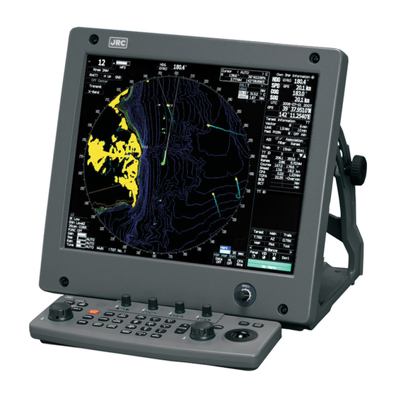
PREFACE Thank you very much for purchasing the JRC marine radar equipment, JMA-5300MK2 series. This equipment is a marine radar equipment designed to obtain safe operation of marine ships. This equipment consists of a radar signal transmitter-receiver unit, a LCD display unit and a scanner unit as its main units. -
Page 8: Before Operation
●Before Operation● Pictorial Indication Various pictorial indications are included in this manual and are shown on these equipment so that you can operate them safety and correctly and prevent any danger to you and/or to other persons and any damage to your property during operation. -
Page 9: Precautions
●PRECAUTIONS● DANGER Never carry out internal inspection or repair work of the equipment by users. Inspection or repair work by uncertified personnel may result in fire hazard or electrocution. For inspection and repair work of equipment components, consult with our branch office, branch shop, sales office, or our distributor in your district. - Page 10 WARNING Never directly touch the internal components of the scanner or indicator. Direct contact with these high-voltage components may cause electrocution. For maintenance, inspection, or adjustment of equipment components, consult with our branch office, branch shop, sales office, or our distributor in your district. To contact our sales department, branch offices, branch shops, and sales offices: Please refer to the "Office List"...
- Page 11 WARNING When cleaning the display screen, do not wipe it too strongly with a dry cloth. Also, do not use gasoline or thinner to clean the screen. Failure to comply will result in damage to the screen surface. Direct exposure to electromagnetic waves at close range will have adverse effects on the human body.
- Page 12 CAUTION A malfunction may occur if the power in the ship is instantaneously interrupted during operation of the radar. In this case, the power should be turned on again. Normally, use the automatic tune mode. Use the manual tune mode only when best tuning is not possible in the automatic tune mode due to deterioration of magnetron.
- Page 13 CAUTION Use the radar only as a navigation aid. The final navigation decision must always be made by the operator him/herself. Making the final navigation decision based only on the radar display may cause accidents such as collisions or running aground. Use target tracking function only as a navigation aid.
- Page 14 CAUTION If a great value is set as a condition for deciding targets as identical, a tracking target near an AIS target is regarded as identical to the AIS target and it may not be displayed any more. For example, when a pilot boat (which is a small target not being tracked) equipped with an AIS function approaches a cargo ship as a tracking target not equipped with an AIS function, the tracking target symbol of the cargo ship may...
- Page 15 CAUTION Make sure to shut off the main power before replacing parts. Failure to comply may result in electrocution or equipment failure. When replacing magnetrons, make sure to shut off the main power and let the equipment stand for more than 5 minutes to discharge the high-voltage circuit.
-
Page 16: The Mounting Point Of The Warning Label
The Mounting Point of the Warning Label Warning Label NDC-1417 Radar Process Unit Warning Label Front face Back face NWZ-173 LCD Monitor - x -... - Page 17 Warning Label NKE-1064 / NKE-3710-8 Scanner Unit - xi -...
- Page 18 Warning Label NQE-3141-4A/8A Interswitch Unit Warning Label NBA-5111 Power Supply - xii -...
-
Page 19: Equipment Appearance
EQUIPMENT APPEARANCE Scanner Unit Type NKE-1064 (9 feet) Scanner Unit Type NKE-3710-8 (8 feet) - xiii -... - Page 20 NDC-1417 Processor Unit (Desktop Type) NWZ-173 LCD Monitor Unit (Desktop Type) NCE-5172 Operation Unit (Desktop Type) NCD-4530 Display Unit (Desktop Type) - xiv -...
-
Page 21: Glossary
GLOSSARY This section describes the main terms used for this equipment and general related maritime terms. Acquisition/Activation zone A zone set up by the operator in which the system should automatically acquire radar targets and activate reported AIS targets when entering the zone. Activated target A target representing the automatic or manual activation of a sleeping target for the display of additional information. - Page 22 Course Over Ground The direction of the ship's movement relative to the earth, measured on board the ship, expressed in angular units from true north CORREL CORRELation CPA/TCPA The distance to the Closest Point of Approach and Time to the Closest Point of Approach.
- Page 23 radar Interference Rejecter InterSWitch Lost AIS target A target symbol representing the last valid position of an AIS target before the reception of its data was lost, or its last dead-reckoned position. Lost tracked target One for which target information is no longer available due to poor, lost or obscured signals.
- Page 24 Radar cross-section Radar cross-section of a target determines the power density returned to the radar for a particular power density incident on the target Range Rings A set of concentric circles labeled by distance from CCRP. Reference target A symbol indicating that the associated tracked stationary target is used as a speed reference for the ground stabilization Relative course The direction of motion of a target relative to own ship motion...
- Page 25 Speed Over the Ground The speed of the ship relative to the earth, measured on board of the ship. Short Pulse STAB STABilization Speed Through Water The speed of the ship relative to the water surface. TCPA Time to Closest Point of Approach to own ship Test target Radar target of known characteristics used for test requirement True Motion...
- Page 26 Variable Range Marker An adjustable range ring used to measure the distance to a target. Waypoint A geographical location on a route indicating a event. - xx -...
-
Page 27: Table Of Contents
CONTENTS PREFACE....................... i BEFORE OPERATION..................ii PRECAUTIONS ....................iii The Mounting Point of the Warning Label ............ix EQUIPMENT APPEARANCE ................xiv GLOSSARY......................xvi 1. GENERAL AND EQUIPMENT COMPOSITION FUNCTIONS ..................... 1-1 1.1.1 FUNCTION OF THIS SYSTEM............1-1 FEATURES ....................1-2 CONFIGURATION ..................1-4 OUTSIDE DRAWINGS ................ - Page 28 OBSERVE AND ADJUST VIDEO.............. 3-5 3.2.1 ADJUST MONITOR BRILLIANCE [BRILL] ......... 3-5 3.2.2 CHANGE OBSERVATION RANGE [RANGE + / - ] ......3-5 3.2.3 TUNE ....................3-6 3.2.4 ADJUST GAIN [GAIN / PL] ..............3-7 3.2.5 SUPPRESS SEA CLUTTER [AUTO-SEA] .......... 3-8 3.2.6 SUPPRESS RAIN / SNOW CLUTTER [AUTO-RAIN] ......
- Page 29 3.4.22 SBAS RECEIVER SETTING (SBAS SETTING) ........ 3-44 3.4.23 DISPLAYING GPS RECEPTION STATUS (GPS STATUS)....3-47 3.4.24 SET RADAR ALARM (RADAR ALARM) ........... 3-48 USE OWN SHIP'S TRACK DATA............3-50 3.5.1 DISPLAY OWN SHIP’S TRACK (DISPLAY OWN TRACK)....3-50 3.5.2 SAVE OWN SHIP'S TRACK DATA (OWN TRACK MEMORY) ..
- Page 30 3.12.1 DISPLAY JRC COASTLINE ROM CARD [MAP] ......3-109 3.12.2 DISPLAY ERC CARD [MAP]............3-109 3.12.3 DISPLAY JRC CHART ON CF CARD (SEL JRC ROM CARD FILE) 3-110 3.12.4 FILL CHARTS (FILL LAND AREA)...........3-111 3.12.5 SET JRC / ERC CHART DISPLAY (JRC / ERC SETTING) ....3-112 3.12.6 DISPLAY C-MAP CARD [MAP] ............
- Page 31 5. OPERATION OF TARGET TRACKING AND AIS USAGE OF TARGET TRACKING FUNCTION............. 5-1 PREPARATION..................5-2 5.1.1 COLLISION AVOIDANCE ..............5-3 5.1.2 DEFINITIONS OF SYMBOLS.............. 5-6 5.1.3 RADAR DISPLAY ................5-9 5.1.4 CURSOR MODES (CURSOR)............5-11 5.1.5 SETTING COLLISION DECISION CRITERIA ........5-13 5.1.6 SETTING CPA RING .................
- Page 32 5.8.3 MODIFYING PLOTTED TARGET DATA ........... 5-64 5.8.4 CANCELING PLOTTED TARGET DATA .......... 5-65 5.8.5 DISPLAYING NUMERIC DATA OF PLOTTED TARGETS ....5-65 6. TRUE AND FALSE ECHOES ON DISPLAY RADAR WAVE WITH THE HORIZON ............6-1 STRENGTH OF REFLECTION FROM THE TARGET ....... 6-3 SEA CLUTTER AND RAIN AND SNOW CLUTTER ........
- Page 33 7.3.2 ADJUSTMENT OF TARGET TRACKING FUNCTION (TT) ....7-24 7.3.3 MAIN BANG SUPPRESSION ADJUSTMENT (MBS)......7-27 MAINTENANCE MENU ................7-28 7.4.1 ANTENNA SAFETY SWITCH (SAFETY SWITCH) ......7-28 7.4.2 INITIALIZATION OF MEMORY AREA (AREA INITIAL) ..... 7-29 7.4.3 SAVE OF INTERNAL MEMORY DATA (CARD1/2)......7-30 7.4.4 CLEAR AND SAVE/RESTORATION OF ANTENNA OPERATION TIME (TXRX TIME) ................
- Page 34 DISPOSAL OF USED MAGNETRON............10-2 10.4 DISPOSAL OF TR-TUBE ................ 10-2 10.5 ABOUT THE CHINA ROHS..............10-3 11. SPECIFICATIONS 11.1 JMA-5352-9R, JMA-5362-8R TYPE RADAR .......... 11-1 11.2 SCANNER (NKE-1064)................11-2 11.3 SCANNER (NKE-3710-8)................ 11-3 11.4 DISPLAY UNIT (NCD-4530) ..............11-4 11.5...
- Page 35 APPENDIX INTERSWITCH (OPTION) NQE-3141 INSTRUCTION MANUAL HOW TO INSERT AND REMOVE A CARD FIG.1 BLOCK DIAGRAM OF RADAR, TYPE JMA-5352-9R, JMA-5362-8R FIG.2 TERMINAL BOARD CONNECTION DIAGRAM, TYPE JMA-5352-9R, JMA-5362-8R FIG.3 TERMINAL BOARD CONNECTION DIAGRAM OF RADAR AND INTERSWITCH UNIT, TYPE NQE-3141 (OPTION) FIG.4 POWER SYSTEM DIAGRAM, TYPE JMA-5352-9R, JMA-5362-8R...
- Page 37 GENERAL AND EQUIPMENT COMPOSITION NAME AND FUNCTION OF CONTROL PANEL KEYS AND FUNCTION OF SOFTWARE BUTTONS BASIC OPERATION MEASUREMENT OF RANGE AND BEARING OPERATION OF ARPA AND AIS TRUE AND FALSE ECHOES ON DISPLAY MAINTENANCE COUNTERMEASURES FOR TROUBLE AND ADJUSTMENT AFTER-SALES SERVICE DISPOSAL SPECIFICATION...
-
Page 39: General And Equipment Composition
SECTION 1 GENERAL AND EQUIPMENT COMPOSITION 1.1 FUNCTIONS..................1-1 1.2 FEATURES...................1-2 1.3 CONFIGURATION................1-4 1.4 OUTSIDE DRAWINGS .................1-5 1.5 GENERAL SYSTEM DIAGRAMS............1-15... -
Page 40: Functions
FUNCTIONS This equipment is a high-performance radar equipment consisting of a scanner unit, a transceiver unit and a high resolution color LCD display unit. 1.1.1 Function of This System The JMA-5300MK2 series is a color radar system. The main functions include: •... -
Page 41: Features
1.2 Features FEATURES Realization of Large, Easy-to-see Screen with High Resolution The 19-inch color LCD with high resolution of 1280 × 1024 pixels can display radar images of 250 mm or more in diameter. Even short-range targets can also be displayed as high-resolution images. Target Detection by Latest Signal Processing Technology The system employs the latest digital signal processing technology to eliminate undesired clutter from the radar video signals that are obtained from the receiver with a wide dynamic range, thus improving the target... - Page 42 Self-diagnostic Program Incorporated The Self-diagnostic program always monitors all the functions of the system. If any function deteriorates, an alarm message will appear on the radar display and an alarm sounds at the same time. Even when the system is operating, the functionality test can be carried out. (except on some functions) Easy Interswitch Operation (Option) If an interswitch unit (option) is connected, up to four JMA-5300MK2 radars can be switched over by performing simple operation.
-
Page 43: Configuration
Specified of scanner, and categories of ship/craft for SOLAS V Transmitted Radar Model Antenna Type Band Rate of Rotation Output Power JMA-5352-9R 9 ft slot antenna 50 kW Approx. 17/14 rpm JMA-5362-8R 8 ft slot antenna 60 kW Approx. 17/14 rpm *The class of emission: P0N (All scanner types) Radar ConFig. -
Page 44: Outside Drawings
OUTSIDE DRAWINGS Fig. 1.1 Outside Drawing of SCANNER UNIT, Type NKE-1064 Fig. 1.2 Outside Drawing of SCANNER UNIT, Type NKE-3710-8 Fig. 1.3 Outside Drawing of SCANNER UNIT, Type NBL-315 Fig. 1.4 Outside Drawing of LCD MONITOR, Type NWZ-173 Fig. 1.5 Outside Drawing of LCD MONITOR, Type NWZ-173 with Stand MPBC42446 (option) Fig. - Page 45 1.4 Exterior Drawings Fig. 1.1 Outside Drawing of SCANNER UNIT, Type NKE-1064...
- Page 46 Fig. 1.2 Outside Drawing of SCANNER UNIT, Type NKE-3710-8...
- Page 47 1.4 Exterior Drawings Fig. 1.3 Outside Drawing of Power Unit, Type NBL-315...
- Page 48 Fig. 1.4 Outside Drawing of LCD MONITOR, Type NWZ-173...
- Page 49 1.4 Exterior Drawings Fig. 1.5 Outside Drawing of LCD MONITOR, Type NWZ-173 with STAND MPBC42446 (option) 1-10...
- Page 50 Fig. 1.6 Outside Drawing of RADAR PROCESS UNIT, Type NDC-1417 1-11...
- Page 51 1.4 Exterior Drawings Fig. 1.7 Outside Drawing of OPERATION UNIT, Type NCE-5172 1-12...
- Page 52 Fig. 1.8 Outside Drawing of OPERATION UNIT, Type NCE-5171 (option) 1-13...
- Page 53 1.4 Exterior Drawings Fig. 1.9 Outside Drawing of RECTIFIER UNIT, Type NBA-5111 (option) 1-14...
-
Page 54: General System Diagrams
GENERAL SYSTEM DIAGRAMS Fig. 1.10 General System Diagram of RADAR, Type JMA-5352-9R Fig. 1.11 General System Diagram of RADAR, Type JMA-5362-8R 1-15... - Page 55 (Ex. Radiotelephone. Communications receiver and direction finder, etc. ) Especially inter-wiring cables between scanner unit and display unit of the radar should not be run parallel with the cables of radio equipment. Fig. 1.10 General System Diagram of RADAR, Type JMA-5352-9R 1-16...
- Page 56 NCT-59A GYRO INTERFACE UNIT (OPTION) 250V-TTYCS-1 (JRC SUPPLY) 5m NCE-5171 OPERATION UNIT (OPTION) NBA-5111 POWER SUPPLY CFQ-5436-5 (OPTION) MAX φ10 (JRC SUPPLY) 5m 0.6/1kV-DPYC-6 (JRC SUPPLY) 5m SHIP'S MAIN SHIP'S MAIN AC100/110/115V 50/60Hz 1φ AC100/110/115V 50/60Hz 1φ AC220/230/240V 50/60Hz 1φ AC220/230/240V 50/60Hz 1φ...
-
Page 57: Names And Functions Of Control Panel Keys And Functions Of Software Buttons
SECTION 2 NAMES AND FUNCTIONS OF CONTROL PANEL KEYS AND FUNCTIONS OF SOFTWARE BUTTONS 2.1 NAMES OF DISPLAY ................. 2-1 2.2 NAMES AND FUNCTIONS OF CONTROL PANEL KEYS....2-10 2.3 FUNCTIONS OF SOFTWARE BUTTONS........2-15... -
Page 58: Names Of Display
NAMES OF DISPLAY Example of screen display In this example, the screen is divided into a number of areas and the names in each area are indicated. Upper left Upper right of the display of the display Own ship's information Target tracking (TT) / AIS information... - Page 59 2.1 Names of Display Automatic acquisition / activation zone Association target Own ship's symbol Ship's heading marker Past position Ship's heading line AIS target number Cursor mark AIS target symbol Tracked target vector Tracked target AIS target vector number Tracked target Radar trails symbol Parallel index lines...
- Page 60 Lower left of the display Upper right of the display...
- Page 61 2.1 Names of Display Lower right of the display Own ship's information About time display mode : Universal Time Coordinate UTC(S) : UTC (System Time) : Local Mean Time LMT(S) : LMT (System Time)
- Page 62 Target tracking (TT) / AIS information Digital information: AIS target information AIS target number Simple display item Ship's name Unread message Call sign MMSI Course Speed TCPA Bearing Ship's heading bearing Rate of turn Range Latitude Latitude / longitude error Longitude Navigation status Destination...
- Page 63 2.1 Names of Display Digital information: Tracked target information Tracked target number Bearing True course Range True speed TCPA No information is displayed if digital information value is not displayed Digital information: Enhancement of cursor position numeric value indication Digital information: Enhancement of EBL / VRM numeric value display...
- Page 64 Digital information: Navigation information Digital information: Depth indication Digital information: Water temperature indication...
- Page 65 2.1 Names of Display Digital information: Wind direction / speed Digital information: Course bar Digital information: Marker Marker bearing Marker latitude Marker range Marker longitude Arrival time...
- Page 66 Menu Brilliance Display information Alarm Alarm indication (The system alarm indicated in red. Other information indicated in blue or yellow.)
-
Page 67: Names And Functions Of Control Panel Keys
2.2 Names and Functions of Control Panel Keys NAMES AND FUNCTIONS OF CONTROL PANEL KEYS The name of each button is described from the following page. See below. 2-10... - Page 68 Track ball Use the track ball to move the cursor mark to any position. For example, use it for setting in each mode and specifying a floating EBL center position and off-center position. [EBL] (Electronic Bearing Line) dial Turn the dial to rotate the bearing of the EBL. By pressing the dial, the selected EBL can be switched.
- Page 69 2.2 Names and Functions of Control Panel Keys [EBL1] / [EBL2] (Electronic Bearing Line 1 / 2) key Use these keys to switch EBL1 / EBL2 to On / Off. If the key is pressed for 2 seconds, the EBL / Cursor Setting menu is opened. [ALARM ACK] (Alarm acknowledgment) key Use this key to acknowledge the alarm such as a failure alarm and a collision alarm.
- Page 70 [VECT R / T / 3] (Vector mode / 3) Use this key to switch vector indication T (true vector) / R (relative vector). During the menu operation, the key functions as a numeric key [3]. [TM / RM / 4] (True Motion / Relative Motion / 4) key Use this key to switch the motion mode between TM (true motion) and RM (relative motion).
- Page 71 2.2 Names and Functions of Control Panel Keys [VRM 1 / 2 ] (Variable Range Marker 1 / 2) key Use this key to set the display of VRM1 / VRM2 to On / Off and acquire the operation right. [ENT] (Enter) key Use this key to confirm menu selection and input of numeric values.
-
Page 72: Functions Of Software Buttons
FUNCTIONS OF SOFTWARE BUTTONS In this radar, the frequently used functions can be directly set from the screen without opening the menu by using the software buttons on the screen for quick handling. The screen is divided into a number of areas and each area is named. Upper left Upper right of the display... - Page 73 2.3 Functions of Software Buttons ①:Heading device switching This function switches the heading device. (GYRO) ⇒ CMPS (Electronic compass) ⇒ G.COM (GPS compass) ⇒ GYRO GYRO If the selected heading device is not connected to the equipment, an alarm is issued. Upper left of the display 2-16...
- Page 74 ①:Range scale switching To increase the observation range scale (maximum 96NM), click + and to reduce the range (minimum 0.125NM), click - . ②:Range rings display On / Off The display of range rings are set to On / Off whenever this button is clicked. When the display is set to On, the interval of the fixed range marker is displayed.
- Page 75 2.3 Functions of Software Buttons Lower left of the display ①:Double zoom switching Use this function to enlarge to double the size the display screen of the position specified by the cursor. If this button is clicked, the zoom mode is set. When the cursor is moved to the radar screen and the [ENT] key is pressed, the screen is enlarged to double the size so that the middle of the cursor and the own ship's position is set to the center of the screen.
- Page 76 ⑥, ⑦, ⑧,and ⑨:Gain, Sea clutter suppression (Sea), Rain / snow clutter suppression (Rain), Tune adjustment Adjust the gain, sea clutter suppression, rain and snow clutter suppression and tune using the track ball. If the button is clicked on, the adjustment value is shown at the upper-right of the cursor. Make adjustments by moving the track ball to the left and right.
- Page 77 2.3 Functions of Software Buttons ②:Mark font / line pattern switching This function switches a mark font / line pattern. If this button is clicked while the cursor mode is □ (mark) or -------- (line), the mark font / line pattern is changed. ③:Mark color / line color switching This function switches a mark color / line color.
- Page 78 Lower right of the display ①:Mark color switching The color of the mark is switched whenever this button is clicked. If the button is clicked for 2 seconds, the Mark Setting menu is opened. ②:Own ship's track interval switching The own ship's track interval is switched whenever this button is clicked. ③:Own ship's track interval unit switching The unit of the own ship's track interval is switched whenever this button is clicked.
- Page 79 2.3 Functions of Software Buttons Own ship's information ①:Heading device switching The heading device is switched whenever this button is clicked. ⇒ CMPS (Electronic compass) ⇒ GCOM (GPS compass) ⇒ GYRO GYRO When the selected heading device is not connected to the equipment, an alarm is issued. ②:Speed sensor switching The speed sensor is switched whenever the button is clicked.
- Page 80 Target tracking (TT) / AIS information ①:Target vector display true / relative switching The tracked target / AIS target vector display is switched to T (true vector) / R (relative vector) whenever this button is clicked. This setting is switched together with the past position display true / relative switching. ②:Target vector length setting Set a vector length of the tracked target / AIS target.
- Page 81 2.3 Functions of Software Buttons ⑧:AIS On / Off The AIS display is switched to On / Off whenever the button is clicked. ⑨:Tracked target symbol display On / Off The tracked target symbol display is switched to On / Off whenever the button is clicked. Use this function to avoid confusion with the AIS symbol.
- Page 82 Digital information: AIS target information Simple display item ① Detail / simple display switching ② Unread message display ①:Detail / simple display switching This function switches the display mode to detail / simple display when AIS target information is displayed. ②:Unread message display When there is an unread message from the AIS target that is displayed, the message is displayed.
- Page 83 2.3 Functions of Software Buttons Digital information: Tracked target information ①:Tracked target numeric value indication scroll This function scrolls the target numbers that are indicated in the tracked target information. Digital information: Navigation information ①:Wind direction / speed numeric value indication true / relative switching The wind direction / speed numeric value indication is switched to T (true) / R (relative) whenever this button is clicked.
- Page 84 Digital information: Wind direction / speed ①:Wind direction / speed numeric value indication true / relative switching The wind direction / speed numeric value indication is switched to T (true) / R (relative) whenever this button is clicked. Menu ①:Digital information display If this button is clicked while the menu screen is open, the menu is closed and control returns to the digital information display.
- Page 85 2.3 Functions of Software Buttons ⑥:Plotter menu If this button is clicked, the Plot Menu is opened. ⑦:Radar trails menu If this button is clicked, the RADAR Trails Setting menu is opened. ⑧:Own ship's track menu If this button is clicked, the Own Track Menu is opened. ⑨:Tool menu If this button is clicked, the Tool Menu is opened.
- Page 86 ②:Panel lighting brilliance switching This function enables the setting of the brilliance of the lighting of the control panel. The brilliance changes whenever this button is clicked. Five levels of settings are available. ③:Radar video brilliance switching Adjust the brightness of the radar video (echo). The brilliance changes whenever this button is clicked.