Sign In
Upload
Manuals
Brands
YOKOGAWA Manuals
Controller
UT520
User Manuals: YOKOGAWA UT520 Indicating Controller
Manuals and User Guides for YOKOGAWA UT520 Indicating Controller. We have
2
YOKOGAWA UT520 Indicating Controller manuals available for free PDF download: User Manual, Instruction Manual
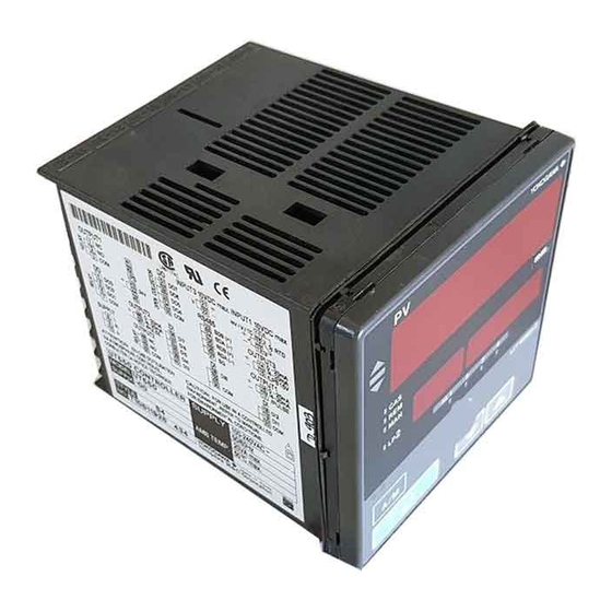
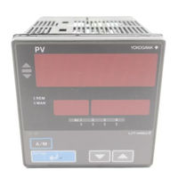
YOKOGAWA UT520 User Manual (109 pages)
Digital Indicating Controllers
Brand:
YOKOGAWA
| Category:
Controller
| Size: 1 MB
Table of Contents
Controllers Applicable to Single-Loop Control
3
How to Use the Manuals
3
Introduction
3
Regarding this User’s Manual
3
Force Majeure
4
Safety Precautions
4
Protection, Safety, and Prohibition against Unauthorized Modification
5
Table of Contents
7
Digital Indicating Controllers Contents
7
1 Installation
9
Model and Suffix Codes
9
Correspondence between the Model and Suffix Codes, and the Contact
9
Input/Output Terminals Provided
9
How to Install
10
External Dimensions and Panel Cutout Dimensions
11
How to Connect Wires
13
For DC Relay Wiring
13
For AC Relay Wiring
13
Cable Specifications and Recommended Cables
14
Recommended Terminal Lugs
14
Terminal Covers
14
Hardware Specifications
15
PV Input Signals
15
Remote Input Signals
15
Feedback Resistance Input
16
Loop Power Supply
16
Retransmission Output
16
Control Output
16
Contact Inputs
17
Contact Outputs
18
Display Specifications
18
Safety and EMC Standards
18
Construction, Installation, and Wiring
19
Power Supply Specifications
20
Signal Isolations
20
Terminal Wiring Diagrams
21
Environmental Conditions
21
UT550 Standard Type, Single-Loop Control
22
Heating/Cooling Type, Single-Loop Heating/Cooling Control
23
Single-Loop Position Proportional Control
24
UT520 Standard Type, Single-Loop Control
25
2 Initial Settings
27
Names and Functions of Front Panel Parts
28
Setting of Main Parameters at the Factory before Shipment
28
Setting PV Input Type (Setting First at Power-On)
29
Instrument Input Range Codes
31
How to Return to a Menu
32
Changing PV Input Type
33
Setting Control Output Type (Except for a Position Proportional Controller)
35
List of Control Output Types
36
Calibrating Valve Position (for a Position Proportional Controller Only)
37
Initializing Parameters
39
Changing Alarm Type
40
List of Alarm Types
42
Description of Multiple Setpoints and PID
43
Available During Operation
45
Monitoring-Purpose Operating Displays Available During Operation
45
Operating Displays for Standard and Position Proportional Controllers
45
Heating/Cooling out Display
46
Operating Displays for a Heating/Cooling Controller
46
SP Display
46
Performing/Canceling Auto-Tuning
47
Setting Target Setpoint (SP)
47
Setting PID Manually
49
Setting Alarm Setpoints
50
Selecting Target Setpoint Numbers (SPN)
51
Switching between Run and Stop
52
Switching between AUTO and man
52
Manipulating Control Output During Manual Operation
53
Manipulating the Control Output During Heating/Cooling Control
53
Controller Behavior and Control Output Manipulation
54
Manipulating the Control Output During Position Proportional Control
55
Switching between Remote (REM) and Local (LCL)
55
4 Troubleshooting and Maintenance
57
Errors at Power on
58
Possible Errors During Operation
59
Remedies if Power Failure Occurs During Operations
59
Power Failure of more than about 2 Seconds
60
Troubleshooting When the Controller Fails to Operate Correctly
61
Maintenance
62
Cleaning
62
Replacing Brackets
62
Attaching Terminal Cover
62
Replacing Parts with a Limited Service Life
64
Replacing Control Output Relays
64
Parameter Map
67
UT550/UT520 Operating Parameter Map
68
UT550/UT520 Setup Parameter Map
70
Lists of Parameters
72
Operation Mode Parameters
72
Operation-Related Parameters
73
Setpoint-, Alarm- and PID-Related Parameters
74
Ten-Segment Linearizer Parameters
76
Setup Parameters
78
Target Setpoint-Related Parameters
78
Alarm-Related Parameters
79
Control Action-Related Parameters
80
Analog Input Computation Parameters
81
Retransmission Output Parameters
82
Deviation Monitor Parameters
83
Security-Related Parameters
83
Contact Output Registration Parameters
84
SELECT Display Parameters
84
Contact Input Registration Parameters
85
UT Mode Parameters
85
Input-Related Parameters
86
Output-Related Parameters
88
Performing Split Computations
89
V-Mode Output
89
Parallel-Mode Output
90
Communication Parameters
91
Motor-Driven Valve Calibration-Related Parameters
91
Parameter-Initializing Parameters
92
Tips about Heating/Cooling Control
92
Tips about Position Proportional Control
93
6 Function Block Diagram and Descriptions
95
Function Block Diagram for Single-Loop Control
96
Function Block Diagram for Single-Loop Heating/Cooling Control
97
Function Block Diagram for Single-Loop Position-Proportional Control
98
Functions and Parameters for Single-Loop Control in Initial State
99
PV Input
99
Operating Parameters
99
Remote Input
100
Contact Input
100
Target Setpoint and PID
101
Contact Output
102
15V DC Loop Power Supply
103
Revision Information
105
Advertisement
YOKOGAWA UT520 Instruction Manual (14 pages)
PC Link Driver
Brand:
YOKOGAWA
| Category:
Controller
| Size: 0 MB
Table of Contents
Table of Contents
1
System Configuration
2
External Device Selection
3
TOP Communication Setting
4
External Device Setting
9
Cable Table
11
Supported Addresses
14
Advertisement
Related Products
YOKOGAWA UT550
YOKOGAWA UT 551
YOKOGAWA UTAdvanced UT32A
YOKOGAWA UT150L
YOKOGAWA UT35A-L
YOKOGAWA NEW GREEN UT450 Series
YOKOGAWA NEW GREEN UT450 2 Series
YOKOGAWA NEW GREEN UT420-00
YOKOGAWA UT Series
YOKOGAWA UT2000
YOKOGAWA Categories
Measuring Instruments
Test Equipment
Transmitter
Controller
Media Converter
More YOKOGAWA Manuals
Login
Sign In
OR
Sign in with Facebook
Sign in with Google
Upload manual
Upload from disk
Upload from URL