Sign In
Upload
Manuals
Brands
Xantrex Manuals
Power Supply
XTR 850 Watt
Xantrex XTR 850 Watt Manuals
Manuals and User Guides for Xantrex XTR 850 Watt. We have
2
Xantrex XTR 850 Watt manuals available for free PDF download: Operating Manual
Xantrex XTR 850 Watt Operating Manual (274 pages)
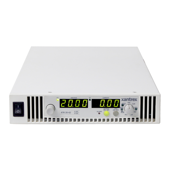
XTR 850 Watt and 1700 Watt Series Programmable DC Power Supply
Brand:
Xantrex
| Category:
Power Supply
| Size: 3 MB
Table of Contents
Operating Manual
1
Power Supply
1
Contact Information
5
About this Manual
7
Conventions Used
7
Font Conventions
8
Related Information
8
Important Safety Instructions
9
Table of Contents
11
1 Introduction
23
Features and Options
24
XTR 850 Watt and XTR 1700 Watt Models
25
Table 1-1 XTR 850 Watt Series Voltage and Current Ranges
25
Table 1-2 XTR 1700 Watt Series Voltage and Current Ranges
25
Front Panel for XTR 850 Watt and XTR 1700 Watt
26
Figure 1-1 Front Panel: XTR 850 Watt and XTR 1700 Watt
26
Figure 1-2 Front Panel Display and Controls
27
Front Panel Display and Controls
27
Rear Panel Connectors on XTR 850 Watt
28
Figure 1-3 XTR 850 Watt Series: 6 V to 40 V Models
28
Figure 1-4 XTR 850 Watt Series: 60 V to 150 V Models
28
Figure 1-5 XTR 850 Watt Series: 300 V to 600 V Models
28
Rear Panel Connectors on XTR 1700 Watt
30
Figure 1-6 XTR 1700 Watt Series: 6 V to 40 V Models
30
Figure 1-7 XTR 1700 Watt Series: 60 V to 600 V Models
30
2 Installation
31
Basic Setup Procedure
32
Table 2-1 Basic Setup Procedure
32
Step 1: Inspecting and Cleaning
33
Initial Inspection
33
Periodic Cleaning
33
Step 2: Location and Mounting
34
Rack Mounting
34
Purchasing Rack Mount Kits
34
Ventilation
34
Step 3: Connecting AC Input Power
35
XTR 850 Watt AC Input Connector
35
XTR 1700 Watt AC Input Connector
36
Figure 2-1 XTR 1700 Watt AC Input Cover and Strain Relief
36
XTR 1700 Watt AC Input Wire
37
XTR 1700 Watt AC Input Wire Connection
37
Table 2-2 XTR 1700 Watt: Recommended AC Input Wire
37
Step 4: Selecting Load Wires
39
Load Wiring
39
Table 2-3 Current Carrying Capacity for Load Wiring
39
Maximum Load Wiring Length for Operation with Sense Lines
40
Figure 2-2 Maximum Load Wire Length for 1 V Line Drop
40
Noise and Impedance Effects
40
Step 5: Performing Functional Tests
41
Powering the Power Supply On/Off
41
Voltage and Current Mode Operation Checks
42
Step 6: Connecting Loads
43
DC Output Connectors
43
Inductive Loads
44
Connecting Single Loads
44
Figure 2-3 Connecting Single Loads
44
Connecting Multiple Loads
45
Step 7: Connecting Remote Sensing
46
Figure 2-4 Remote Sense Connection
46
3 Local Operation
49
Introduction
50
Configuring Settings from the Front Panel
50
Using the 9-Position Mode Control Knob
50
Using the Rotary Knob/Enter Button
50
Coarse and Fine Adjustment Modes
50
Figure 3-1 9 Position Mode Control Knob
50
Table 3-1 Select and Set from the Front Panel
51
Navigating the Menu System
52
Setting VOL and CUR Modes
52
Normal Display Mode and Inactivity Timeout
54
Figure 3-2 Front Panel Menu System
55
Display Messages on the Front Panel
56
Table 3-2 Front Panel Display Text
56
Standard Operation
58
Operating Modes
58
Figure 3-3 Operating Modes
60
Shipped Configuration (Local Operation)
62
Turning the Output On/Off
62
Table 3-3 Shipped Configuration
62
Turning the Auxiliary Output On/Off
63
Output Auto Start Mode (Auto Restart)
63
Auxiliary Auto Start Mode
64
Alarms and Errors
65
Table 3-4 Alarm Order of Precedence
65
Clearing Alarms
66
Front Panel ALARM LED
67
Alarm Masking
68
Table 3-5 Alarm Mask Bit Positions
68
Alarm Output Latching
69
Table 3-6 Alarm Latch Bit Positions
69
Setting Foldback Mode
70
Resetting Activated Foldback Protection
71
Using over Voltage Protection (OVP)
72
Defining the OVP Set Point
72
Using under Voltage Protection (UVP)
73
Defining the UVP Set Point
73
Over Current Protection (OCP)
73
Using over Temperature Protection Lock (OTP)
74
Defining the OTP Mode
74
Resetting in Latch Mode
74
Current Configuration Memory Settings
75
Table 3-7 Power Cycle Saved/Recalled Settings
75
User Setting Memory Locations
76
Saving User Setting Memory Locations
76
Table 3-8 User Accessible Saved/Recalled Settings
76
Recalling User Setting Memory Locations
77
Local Lockout
78
Enabling Local Lockout
78
Disabling Local Lockout
78
Using the External Shutdown Function
79
Activating the External Shutdown Function
79
Controlling the External Shutdown Function
79
Defining the Polarity of the External Shutdown Signal
79
Interlock Function
81
Defining the Interlock Mode
81
Power on Status Signal
81
Hardware Malfunction Alarms
82
Resetting the Power Supply
83
Table 3-9 Power Supply Default Settings
84
Using Multiple Power Supplies
85
Figure 3-4 Split Supply Operation
86
Configuring Multiple Supplies for Series Operation
87
Figure 3-5 Series Operation
87
Figure 3-6 Load Connections in Remote Sensing Mode
88
Configuring Multiple Supplies for Current Sharing Operation (APG Method)
89
Setting Foldback Protection
90
Connecting to the Load in Local Sensing Mode (Parallel Control Method)
91
Figure 3-7 Load Connections in Local Sensing Mode
91
Connecting to the Load in Remote Sensing Mode (Parallel Control Method)
92
Figure 3-8 Load Connections in Remote Sensing Mode (Parallel Control Method)
92
4 Analog Programming (APG) and Isolated Analog Programming (ISOL)
93
Introduction
94
Analog Programming (APG) of Output Voltage and Output Current
94
Remote Programming Options
95
Table 4-1 Monitor Lines
95
Table 4-2 Remote Programming Options
96
Analog Programming (APG) Connector J1
97
Figure 4-1 APG Connector Terminals
97
Table 4-3 APG Pins and Functions J1
98
Figure 4-2 Inserting Screwdriver into Spring Terminal Block
99
Figure 4-3 APG and DC Output Connector
99
Analog Programming Mode
101
Analog Programming with External Voltage Source
101
Figure 4-4 Programming Output Voltage Using an External Voltage Source
101
Figure 4-5 Programming Output Current Using an External Voltage Source
101
Voltage-Controlled Voltage APG Setup
102
Voltage-Controlled Current APG Setup
104
Analog Programming with External Resistor
106
Figure 4-6 Programming Output Voltage Using an External Resistor
106
Figure 4-7 Programming Output Current Using an External Resistor
106
Resistive-Controlled Voltage APG Setup
107
Resistive-Controlled Current APG Setup
109
Voltage and Current Readback
110
Figure 4-8 Voltage Readback Using APG Connector J1
110
Figure 4-9 Current Readback Using APG Connector J1
110
Isolated Analog Programming Mode (ISOL)
111
AUX Output and Isolated Analog Programming (ISOL) Connector
111
Figure 4-10 aux Output and ISOL Connector Pinout
111
Table 4-4 aux Output and ISOL Connector Pins and Functions J3
112
Figure 4-11 Programming Output Voltage Using an Isolated External Voltage Source
113
Figure 4-12 Programming Output Current Using an Isolated External Voltage Source
113
Voltage-Controlled Voltage ISOL Setup
114
Activating ISOL Programming Voltage Mode
114
Deactivating ISOL Voltage Mode
114
Voltage-Controlled Current ISOL Setup
115
Deactivating ISOL Current Mode
116
Query for ISOL Current Input Level
116
Figure 4-13 Programming Output Voltage Using an Isolated External Resistor
117
Figure 4-14 Programming Output Current Using an Isolated External Resistor
117
Resistive-Controlled Voltage ISOL Setup
118
Resistive-Controlled Current ISOL Setup
119
Voltage and Current Readback (Isolated)
121
Figure 4-15 Isolated Voltage Monitoring
121
Figure 4-16 Isolated Current Monitoring
121
Query Remote Control Source State
121
5 Remote Operation
123
Introduction
124
Hardware and Connection Setup
124
Configuring Remote Control Using
124
Figure 5-1 Remote Control Connectors
125
Table 5-1 Remote Control Connector Pins and Functions J4 and J6
125
Figure 5-2 DB-9 Pinout
126
Table 5-2 DB-9 Pinouts
126
Table 5-3 RJ-45 Pinouts
126
Figure 5-3 RS-232 Communication Cable with DB-9 Pinout
127
Figure 5-4 DB-25 Pinout
127
Table 5-4 DB-25 Pinouts
127
Completing the Setup
128
Figure 5-5 RS-232 Communication Cable with DB-25 Pinout
128
Configuring Remote Control Using
129
Table 5-5 DB-9 Pinouts
129
Table 5-6 RJ-45 Plug Pinouts
129
Table 5-7 RJ-45 Plug on Slave Unit
130
Configuring Remote Control Using the USB Connector
131
Setting up the PC to Use the USB Connection
131
Figure 5-7 RS-485 Communication Cable from Master to Slave Unit
131
Figure 5-8 Found New Hardware Wizard
132
Figure 5-9 Install Hardware Device Drivers
133
Verifying Installation
134
Figure 5-10 Completing the New Hardware Wizard
134
Figure 5-11 Device Manager
135
Figure 5-12 Communications Port (COM1) Properties
135
Complete the Setup
136
Ethernet (ENET) or GPIB Connector (Optional)
136
Figure 5-13 Completing the New Hardware Wizard
136
Multiple Power Supply Connections to RS-485 Bus
137
Figure 5-14 Multi Power Supply Connection to RS-485 Bus
137
Multiple Power Supply Connections to ENET
138
Figure 5-15 Multi Power Supply Connection to ENET
138
Terminal Configuration
139
Data Format
139
End of Message
139
Hyperterminal
139
Figure 5-16 USB Settings
140
Figure 5-17 ASCII Setup
141
Selecting the Appropriate Communication Port
142
Multichannel Address Setting
143
Remote Interface Addressing
143
Multichannel Commands Explained
144
Table 5-8 Rules for Multichannel Responses
144
Status Reporting in SCPI
145
Figure 5-18 SCPI Status Reporting Model
146
Status Registers Model from IEEE 488.2
147
Figure 5-19 IEEE 488.2 Register Model
147
Status Byte
148
Error/Event Queue (ERR)
148
Questionable Status Register Summary (QSR)
148
Table 5-9 Status Byte Summary Register
148
Message Available (MAV)
149
Standard Event Status Summary (ESB)
149
Master Summary Status (MSS)
149
Request Service (RQS)
149
Operation Status Register Summary (OSR)
149
Standard Event Status Register (SESR)
151
Figure 5-20 Summary of Standard Event Status Register
152
Table 5-10 Standard Event Status Register
152
Operation Complete
153
Wait-To-Continue Command
153
Standard SCPI Register Structure
154
Figure 5-21 SCPI Register Model
154
Figure 5-22 Operation Status Register Fanout
155
Table 5-11 Operation Status Register
156
Current Share Sub-Register
157
Table 5-12 Operation Shutdown Status Register
157
Table 5-13 Operation Shutdown Protection Status Register
157
Operation Status Register Commands
158
Table 5-14 Operation Cshare Status Register
158
Current Sharing Sub-Register Commands
159
Shutdown Sub-Register Commands
160
Protection Sub-Register Commands
161
Set Protection Negative Transition Filter
162
Questionable Status Register
162
Figure 5-23 SCPI Questionable Registers Fanout
163
Table 5-15 Questionable Status Register
164
Table 5-16 Questionable Voltage Status Register
164
Voltage Sub-Register
164
Questionable Status Register Commands
165
Table 5-17 Questionable Temperature Status Register
165
Temperature Sub-Register
165
Voltage Status Register Commands
166
Temperature Status Register Commands
167
Set Temperature Status Negative Transition Filter
168
SCPI Error/Event Queue
168
Reset Command
170
Clear All Status Registers
171
Clear Status Command
171
SCPI Preset Status
171
Command Line Help System
172
Table 5-18 Preset Values of User Configurable Registers
172
Querying Help for Legacy Command Headers
174
Locking and Unlocking the Front Panel
177
Auto Sequence Programming
177
Setting Dwell Time
178
Storing an Auto Sequence Program
178
Repeating an Auto Sequence Program
182
Configure Other Protection Mechanisms
184
Foldback Protection
184
Setting the Foldback Mode
184
Over Temperature Protection
185
Interlock Enable/Disable
185
Save and Recall
186
Set Analog Programming Level
186
Set Remote Programming Interface
187
Protection Mask (Enable Alarms)
187
Table 5-19 Alarms Bit Mask
188
6 Calibration and Troubleshooting
189
Introduction
190
Main Voltage and Current Calibration Principle
190
Understanding the Problem
190
Step 1: Gain Calibration
191
Figure 6-1 Offset (Intercept) Error and Gain (Slope) Error
191
Figure 6-2 Calibration: Step 1 Gain Calibration
191
Step 2: Offset Calibration
192
Step 3: Recalibrate Gain
192
Figure 6-3 Calibration: Step 2 Offset Calibration
192
Figure 6-4 Calibration: Step 3 Recalibrate Gain
192
Calibrating the Output Voltage
193
Gain Calibration
193
Offset Calibration
193
Calibrating the Output Current
194
Gain Calibration
194
Offset Calibration
194
Over Voltage Protection Calibration
195
Non-Isolated Analog Programming Calibration
196
Non-Isolated Voltage Monitoring Calibration
196
Non-Isolated Current Monitoring Calibration
197
Non-Isolated Voltage Programming of Voltage Calibration
197
Non-Isolated Resistive Programming of Voltage Calibration
198
Non-Isolated Voltage Programming of Current Calibration
199
Non-Isolated Resistive Programming of Current Calibration
199
Calibration Procedure for Isolated Modes
201
Isolated Voltage Monitoring Calibration
201
Isolated Current Monitoring Calibration
201
Isolated Voltage Programming of Voltage Calibration
202
Isolated Resistive Programming of Voltage Calibration
203
Isolated Voltage Programming of Current Calibration
204
Isolated Resistive Programming of Current Calibration
204
Storing and Loading Calibration Parameters
205
Restore Factory Calibration
206
User Diagnostics
206
Emergency Shutdown
206
Unusual or Erratic Operation
207
Troubleshooting for Operators
207
Table 6-1 Troubleshooting
207
A SCPI Command Reference
209
Codes and Standards
210
SCPI Conformance Information
210
IEEE 488.2/SCPI Syntax and Style
210
SCPI Command Hierarchy
211
Using SCPI Commands
212
Using Minimum and Maximum
213
Using Queries
213
Parameter Types
214
SPCI Command Tree
216
SCPI Command Summary
222
Table A-1 IEEE 488.2 Commands
222
Table A-3 SCPI Commands for Output Control
224
Table A-2 Readback Commands
224
Table A-4 SCPI Commands for Calibration
226
Table A-5 SCPI Commands to Clear All Protection Mechanisms
229
Table A-6 SCPI Commands for Foldback Protection
229
Table A-7 SCPI Commands for Power
229
Table A-8 SCPI Commands for Triggering
230
Table A-9 System Commands
230
Table A-10 Status Commands
234
Table A-12 Auto Sequence Commands
242
Table A-11 Protection Commands
242
Error Messages
245
Command Error List
246
Table B-1 Command Error List
246
Execution Error List
247
Device-Specific Error List
248
Table B-2 Execution Error List
248
Table B-3 Device-Specific Error List
248
Query Error List
249
Table B-4 Query Error List
249
Specifications
251
100 C Specifications
252
Electrical Specifications for XTR 850 Watt
252
Table C-1 XTR 850 Watt Electrical Specifications for 6 V to 600 V Models
252
AC Line Input Specifications for XTR 850 Watt
253
Electrical Specifications for XTR 1700 Watt
254
Table C-2 XTR 1700 Watt Electrical Specifications for 6 V to 600 V Models
254
AC Line Input Specifications for XTR 1700 Watt
255
Remote Operation
256
Table C-3 Remote Operation
256
Common Specifications for All Models
257
Figure C-1 XTR 850 Watt Mechanical Dimensions: 6 to 40 V Models
259
Figure C-2 XTR 850 Watt Mechanical Dimensions: 60 V to 600 V Models
260
Figure C-3 XTR 1700 Watt Mechanical Dimensions: 6 V to 40 V Models
261
Figure C-4 XTR 1700 Watt Mechanical Dimensions: 6 V to 40 V Models DC Output Cover
262
Figure C-5 XTR 1700 Watt Mechanical Dimensions: 60 V to 600 V Models
263
Warranty and Product Information
265
Return Material Authorization Policy
267
Information about Your System
268
Out of Warranty Service
268
Return Procedure
268
Index
269
Advertisement
Xantrex XTR 850 Watt Operating Manual (286 pages)
XTR 850 Watt Series Programmable DC Power Supply
Brand:
Xantrex
| Category:
Power Supply
| Size: 3 MB
Table of Contents
Operating Manual
1
Power Supply
1
Conventions Used
7
Font Conventions
8
Related Information
8
Important Safety Instructions
9
Table of Contents
11
1 Introduction
23
Features and Options
24
XTR 850 Watt Models (Firmware V1.09 and Below)
25
Table 1-1 XTR 850 Watt Series Voltage and Current Ranges
25
Front Panel
26
Figure 1-1 XTR 850 Watt Front Panel
26
Figure 1-2 Front Panel Display and Controls
27
Front Panel Display and Controls
27
Rear Panel Connectors
28
Figure 1-3 Rear Panel: 6 V to 40 V Models
28
Figure 1-4 Rear Panel: 60 V to 150 V Models
28
Figure 1-5 Rear Panel: 300 V to 600 V Models
28
2 Installation
31
Basic Setup Procedure
32
Table 2-1 Basic Setup Procedure
32
Step 1: Inspecting and Cleaning
33
Initial Inspection
33
Periodic Cleaning
33
Step 2: Location and Mounting
34
Rack Mounting
34
Purchasing Rack Mount Kits
34
Ventilation
34
Step 3: Connecting AC Input Power
35
AC Input Connector
35
Step 4: Selecting Load Wires
36
Load Wiring
36
Table 2-2 Current Carrying Capacity for Load Wiring
36
Figure 2-1 Maximum Load Wire Length for 1 V Line Drop
37
Step 5: Performing Functional Tests
38
Powering the Power Supply On/Off
38
Voltage and Current Mode Operation Checks
39
Step 6: Connecting Loads
40
DC Output Connectors
40
Inductive Loads and Batteries
41
Figure 2-2 Diode Placement
41
Connecting Single Loads
42
Connecting Multiple Loads
42
Figure 2-3 Connecting Single Loads
42
Step 7: Connecting Remote Sensing
43
Figure 2-4 Remote Sense Connection
43
3 Local Operation
45
Introduction
46
Configuring Settings from the Front Panel
46
Using the 9-Position Mode Control
46
Using the Rotary Adjust/Enter Control
46
Figure 3-1 9-Position Mode Control
46
Coarse and Fine Adjustment Modes
47
Table 3-1 Select and Set from the Front Panel
48
Navigating the Menu System
49
Setting VOLTS and AMPS Modes
49
Normal Display Mode and Inactivity Timeout
51
Figure 3-2 Front Panel
51
Figure 3-3 Front Panel Menu System
52
Display Messages on the Front Panel
53
Table 3-2 Front Panel Display Text
54
Standard Operation
55
Operating Modes
55
Constant Voltage Mode Operation
56
Constant Current Mode Operation
56
Automatic Mode Crossover
56
Figure 3-4 Operating Modes
57
Shipped Configuration (Local Operation)
59
Enabling the Output
59
Table 3-3 Shipped Configuration
59
Enabling the Auxiliary Output
60
Output Auto Start Mode (Auto Restart)
60
Auxiliary Auto Start Mode
61
Alarms and Errors
62
Table 3-4 Alarm Order of Precedence
62
Clearing Alarms
63
Front Panel ALARM LED
64
Alarm Masking
65
Table 3-5 Alarm Mask Bit Positions
65
Alarm Output Latching
66
Table 3-6 Alarm Latch Bit Positions
66
Setting Foldback Mode
67
Resetting Activated Foldback Protection
68
Using over Voltage Protection (OVP)
69
Defining the OVP Set Point
70
Using under Voltage Protection (UVP)
71
Defining the UVP Set Point
72
Over Current Protection (OCP)
72
Using over Temperature Protection Lock (OTP)
73
Defining the OTP Mode
73
Resetting in Latch Mode
73
Using the External Shutdown Function
74
Activating the External Shutdown Function
74
Controlling the External Shutdown Function
74
Defining the Polarity of the External Shutdown Signal
75
Interlock Function
76
Defining the Interlock Mode
76
Power on Status Signal
77
Hardware Malfunction Alarms
77
Current Configuration Memory Settings
78
Table 3-7 Power Cycle Saved/Recalled Settings
78
User Setting Memory Locations
79
Saving User Setting Memory Locations
79
Table 3-8 User Accessible Saved/Recalled Settings
79
Recalling User Setting Memory Locations
80
Local Lockout
81
Enabling Local Lockout
81
Disabling Local Lockout
81
Resetting the Power Supply
83
Table 3-9 Power Supply Default Settings
84
Using Multiple Power Supplies
85
Figure 3-5 Split Supply Operation
86
Configuring Multiple Supplies for Series Operation
87
Figure 3-6 Series Operation
87
Figure 3-7 Load Connections in Remote Sensing Mode
88
Configuring Multiple Supplies for Current Sharing Operation (APG Method)
89
Setting Foldback Protection
90
Connecting to the Load in Local Sensing Mode (Parallel Control Method)
91
Figure 3-8 Load Connections in Local Sensing Mode
91
Connecting to the Load in Remote Sensing Mode (Parallel Control Method)
92
Figure 3-9 Load Connections in Remote Sensing Mode (Parallel Control Method)
92
4 Analog Programming (APG) and Isolated Analog Programming (ISOL)
93
Introduction
94
Analog Programming (APG) of Output Voltage and Output Current
94
Remote Programming Options
95
Table 4-1 Monitor Lines
95
Auxiliary Outputs
96
Table 4-2 Remote Programming Options
96
Analog Programming (APG) Connector J1
97
Figure 4-1 APG Connector Terminals
97
Table 4-3 APG Pins and Functions J1
98
Figure 4-2 Inserting Screwdriver into Spring Terminal Block
99
Figure 4-3 APG and DC Output Connector
99
Analog Programming Mode
101
Analog Programming with External Voltage Source
101
Figure 4-4 Programming Output Voltage Using an External Voltage Source
101
Figure 4-5 Programming Output Current Using an External Voltage Source
101
Voltage-Controlled Voltage APG Setup
102
Activating APG Voltage Mode
102
Deactivating APG Voltage Mode
102
Voltage-Controlled Current APG Setup
104
Activating APG Current Mode
104
Deactivating APG Current Mode
104
Analog Programming with External Resistor
106
Figure 4-6 Programming Output Voltage Using an External Resistor
106
Figure 4-7 Programming Output Current Using an External Resistor
106
Resistive-Controlled Voltage APG Setup
107
Resistive-Controlled Current APG Setup
109
Voltage and Current Readback
111
Figure 4-8 Voltage Readback Using APG Connector J1
111
Figure 4-9 Current Readback Using APG Connector J1
111
Isolated Analog Programming Mode (ISOL)
112
AUX Output and Isolated Analog Programming (ISOL) Connector
112
Figure 4-10 aux Output and ISOL Connector Pinout
112
Table 4-4 aux Output and ISOL Connector Pins and Functions J3
113
Figure 4-11 Programming Output Voltage Using an Isolated External Voltage Source
115
Figure 4-12 Programming Output Current Using an Isolated External Voltage Source
115
Voltage-Controlled Voltage ISOL Setup
116
Activating ISOL Programming Voltage Mode
116
Deactivating ISOL Voltage Mode
116
Voltage-Controlled Current ISOL Setup
118
Activating ISOL Programming Current Mode
118
Deactivating ISOL Current Mode
118
Figure 4-13 Programming Output Voltage Using an Isolated External Resistor
120
Figure 4-14 Programming Output Current Using an Isolated External Resistor
120
Resistive-Controlled Voltage ISOL Setup
121
Resistive-Controlled Current ISOL Setup
123
Voltage and Current Readback (Isolated)
125
Figure 4-15 Isolated Voltage Monitoring
125
Figure 4-16 Isolated Current Monitoring
125
5 Remote Operation
127
Introduction
128
Hardware and Connection Setup
129
Configuring Remote Control Using
129
Figure 5-1 Remote Control Connectors
129
Table 5-1 Remote Control Connector Pins and Functions J4 and J6
130
Table 5-2 DB-9 Pinouts
130
Table 5-3 RJ-45 Pinouts
130
Figure 5-2 RS-232 Communication Cable with DB-9 Pinout
131
Figure 5-3 DB-25 Pinout
131
Table 5-4 DB-25 Pinouts
131
Figure 5-4 RS-232 Communication Cable with DB-25 Pinout
132
Completing the Setup
132
Configuring Remote Control Using
133
Table 5-5 DB-9 Pinouts
133
Table 5-6 RJ-45 Plug Pinouts
133
Figure 5-6 RS-485 Communication Cable from Master to Slave Unit
134
Table 5-7 RJ-45 Plug on Slave Unit
134
Configuring Remote Control Using the USB Connector
135
Setting up the PC to Use the USB Connection
135
Figure 5-7 Found New Hardware Wizard
136
Figure 5-8 Install Hardware Device Drivers
136
Figure 5-9 Completing the New Hardware Wizard
137
Figure 5-10 Device Manager
138
Figure 5-11 Communications Port (COM1) Properties
139
Figure 5-12 Completing the New Hardware Wizard
139
Complete the Setup
140
Ethernet (ENET) or GPIB Connector (Optional)
141
Multiple Power Supply Connections to RS-485 Bus
141
Figure 5-13 Multi Power Supply Connection to RS-485 Bus
141
Multiple Power Supply Setup
142
Terminal Configuration
143
Data Format
143
End of Message
143
Hyperterminal
143
Figure 5-14 USB Settings
144
Figure 5-15 ASCII Setup
145
Selecting the Appropriate Communication Port
146
Data Rate Setting (Kbps)
146
Multichannel Address Setting
147
Remote Interface Addressing
148
Table A-3 Table
148
Multichannel Commands Explained
149
Table 5-8 Rules for Multichannel Responses
149
Status Reporting in SCPI
151
Figure 5-16 SCPI Status Reporting Model
152
Table C-2 Remote Operation
152
Status Registers Model from IEEE 488.2
153
Figure 5-17 IEEE 488.2 Register Model
153
Status Byte
154
Error/Event Queue (ERR)
154
Questionable Status Register Summary (QSR)
154
Table 5-9 Status Byte Summary Register
154
Message Available (MAV)
155
Standard Event Status Summary (ESB)
155
Master Summary Status (MSS)
155
Request Service (RQS)
155
Operation Status Register Summary (OSR)
156
Service Request Enable Register
156
Query the Status Byte
156
Standard Event Status Register (SESR)
157
Figure 5-18 Summary of Standard Event Status Register
158
Table 5-10 Standard Event Status Register
158
Standard SCPI Register Structure
160
Figure 5-19 SCPI Register Model
160
Operation Status Register
161
Figure 5-20 Operation Status Register Fanout
161
Table 5-11 Operation Status Register
162
Table 5-12 Operation Shutdown Status Register
163
Table 5-13 Operation Shutdown Protection Status Register
163
Current Share Sub-Register
164
Table 5-14 Operation Cshare Status Register
164
Operation Status Register Commands
165
Current Sharing Sub-Register Commands
166
Shutdown Sub-Register Commands
167
Protection Sub-Register Commands
168
Questionable Status Register
169
Table 5-15 Questionable Status Register
169
Figure 5-21 SCPI Questionable Registers Fanout
170
Table 5-16 Questionable Voltage Status Register
172
Table 5-17 Questionable Temperature Status Register
172
Temperature Sub-Register
172
Voltage Sub-Register
172
Questionable Status Register Commands
173
Voltage Status Register Commands
174
Temperature Status Register Commands
175
SCPI Error/Event Queue
176
Reset Command
178
Clear All Status Registers
179
SCPI Preset Status
180
Table 5-18 Preset Values of User Configurable Registers
180
Command Line Help System
181
Locking and Unlocking the Front Panel
186
Auto Sequence Programming
186
Readback and Troubleshooting an Auto Sequence Program
188
Running an Auto Sequence Program
190
Configure Other Protection Mechanisms
193
Foldback Protection
193
Over Temperature Protection
194
Interlock Enable/Disable
194
Save and Recall
195
Set Analog Programming Level
195
Set Remote Programming Interface
196
Protection Mask (Enable Alarms)
197
Table 5-19 Alarms Bit Mask
197
A SCPI Command Reference
199
SCPI Conformance Information
200
IEEE 488.2/SCPI Syntax and Style
200
SCPI Command Hierarchy
201
Using SCPI Commands
202
Terminating Characters
204
Common Commands
204
Parameter Types
205
SPCI Command Tree
206
B Calibration and Troubleshooting
235
Introduction
236
Main Voltage and Current Calibration Principle
237
Understanding the Problem
237
Figure B-1 Offset (Intercept) Error and Gain (Slope) Error
237
Step 1: Gain Calibration
238
Step 2: Offset Calibration
238
Figure B-2 Calibration: Step 1 Gain Calibration
238
Figure B-3 Calibration: Step 2 Offset Calibration
238
Step 3: Recalibrate Gain
239
Figure B-4 Calibration: Step 3 Recalibrate Gain
239
Calibrating the Output Voltage
240
Gain Calibration
240
Offset Calibration
240
Calibrating the Output Current
241
Gain Calibration
241
Offset Calibration
242
Over Voltage Protection Calibration
243
Non-Isolated Analog Programming Calibration
244
Non-Isolated Voltage Monitoring Calibration
244
Non-Isolated Current Monitoring Calibration
245
Non-Isolated Voltage Programming of Voltage Calibration
246
Non-Isolated Resistive Programming of Voltage Calibration
247
Non-Isolated Voltage Programming of Current Calibration
248
Non-Isolated Resistive Programming of Current Calibration
249
Calibration Procedure for Isolated Modes
250
Isolated Voltage Monitoring Calibration
250
Isolated Current Monitoring Calibration
251
Isolated Voltage Programming of Voltage Calibration
252
Isolated Resistive Programming of Voltage Calibration
253
Isolated Voltage Programming of Current Calibration
254
Isolated Resistive Programming of Current Calibration
255
Calibrating the Input Voltage APG Signal
256
Calibrating the Input Current APG Signal
257
Storing and Loading Calibration Parameters
259
Restore Factory Calibration
260
User Diagnostics
261
Emergency Shutdown
261
Unusual or Erratic Operation
261
Troubleshooting for Operators
262
Table B-1 Troubleshooting
262
Error Messages
263
Command Error List
265
Table B-1 Command Error List
265
Execution Error List
266
Table B-2 Execution Error List
266
Device-Specific Error List
267
Table B-3 Device-Specific Error List
267
Query Error List
268
Table B-4 Query Error List
268
Specifications
269
100 C Specifications
271
Electrical Specifications for XTR 850 Watt
271
Common Specifications for All Models
273
Figure C-1 XTR 850 Watt Mechanical Dimensions: 6 to 40 V Models
275
Figure C-2 XTR 850 Watt Mechanical Dimensions: 60 V to 600 V Models
276
Warranty and Product Information
277
Return Material Authorization Policy
279
Information about Your System
280
Out of Warranty Service
280
Return Procedure
280
Index
283
Advertisement
Related Products
Xantrex XTR 850 Watt Series
Xantrex XTR 8-100
Xantrex XTR 80-10.5
Xantrex XTR 8-200
Xantrex XTR 80-21
Xantrex XTR 40-21
Xantrex XTR 60-14
Xantrex XTR 150-5.6
Xantrex XTR 600-1.4
Xantrex XTR 60-28
Xantrex Categories
Inverter
Power Supply
Battery Charger
Power Pack
Controller
More Xantrex Manuals
Login
Sign In
OR
Sign in with Facebook
Sign in with Google
Upload manual
Upload from disk
Upload from URL