Sign In
Upload
Manuals
Brands
Wintriss Manuals
Controller
SmartPAC PRO
Wintriss SmartPAC PRO Press Controller Manuals
Manuals and User Guides for Wintriss SmartPAC PRO Press Controller. We have
5
Wintriss SmartPAC PRO Press Controller manuals available for free PDF download: User Manual, Integration Manual, Installation Manual, Instruction Sheet
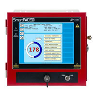
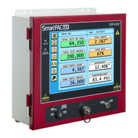
Wintriss SmartPAC PRO User Manual (318 pages)
Press Automation Control
Brand:
Wintriss
| Category:
Industrial Equipment
| Size: 18 MB
Table of Contents
Table of Contents
7
Table of Contents
18
Setup Sheets
19
Wiring Diagrams
19
Chapter 1 - Introduction to Smartpac Pro
25
Figure 1-1. Smartpac PRO Front Panel
26
Smartpac PRO Options
27
Smartpac PRO Standard Features
27
Resolver-Based Operation
28
Smartpac PRO Settings
28
Dipropac die Protection Module (Optional)
29
Procampac Programmable Cam Switch (Optional)
29
Smartpac Pro's Modes of Operation
29
Figure 1-2. "Top" Screen for each of Smartpac Pro's 3 Operating Modes
30
Table 1-1. Initialization, Program and Run Modes: Entry and Exit Procedures
30
Initialization Mode
31
Program Mode
31
Run Mode
31
Figure 1-3. Numeric Keypad
32
On-Screen Numeric Keypad
32
Smartpac PRO User Interface
32
Figure 1-4. Smartpac PRO On-Screen Keyboard
33
On-Screen Keyboard
33
Control and Navigation Buttons
34
Table 1-2. Control Buttons on Smartpac PRO
34
Figure 1-5. Save to USB Disk
35
Saving Directly to a USB Drive
35
Screen Captures
35
Creating and Using Dashboards
36
Exporting Saved Screen Capture Images to a USB Disk
36
Figure 1-6. USB Transfer Complete
36
Figure 1-7. USB Disk Error Message
36
Figure 1-8. Favorites Button
36
View Screen Capture Images on Smartpac PRO
36
Figure 1-10. Add Screen to Favorites
37
Figure 1-9. Favorites Screen
37
Creating a Dashboard
38
Figure 1-11. Delete Screens from Favorites
38
Figure 1-12. Dashboard Configuration Screen
38
Figure 1-13. 1 X 2 Dashboard Example
39
Figure 1-14. 2 X 2 Dashboard Example
39
Figure 1-15. Dashboard Configuration Screen, Display Area 1 Filled
39
Figure 1-16. Dashboard Configuration Preview
40
Figure 1-17. Dashboard Button
40
Showing the Currently Selected Dashboard
40
Smartpac PRO Specifications
41
Table 1-3. Smartpac PRO Specifications
41
Chapter 2 - Installing Smartpac PRO
43
Table of Contents
44
Before You Start
45
Installation Guidelines
45
Terminating Cable Shields
46
Checking the Press
47
Figure 2-1. Smartpac PRO Mounting Dimensions
47
Mounting the Smartpac PRO Control Enclosure
47
Installing Smartpac PRO as a Panel Mount
48
Figure 2-2. Smartpac PRO Panel Mount Cutout Dimension
49
Figure 2-3. Smartpac PRO Panel Mount Dimensions
50
Installing Smartpac PRO in a pendant
50
Figure 2-4. pendant Installation
51
Table 2-1. Connecting HMI to RTS Boards for a Pendant-Mounted Display
51
Installing the Resolver
52
Mounting the Resolver
54
Wiring the Resolver
54
Connecting Power Wiring - AC Powered Units
55
Table 2-2. Resolver Wiring
55
Connecting Power Wiring - 24 VDC Powered Units
57
Connecting Stop Circuits and Input Check Circuit
57
Making Wiring Connections
58
Setting the Input Check Voltage Switch
58
Table 2-3. Stop and Input Check Circuit Wiring Connections: TB4
58
Adding or Upgrading Dipropac or Procampac Option
60
Connecting Dipro Sensor Interface to Smartpac PRO
62
Table 2-4. Dipro Sensor Interface (DSI) 2 to Smartpac PRO Wiring, Sensors 1-8
63
Table 2-5. Dipro Sensor Interface (DSI) 2 to Smartpac PRO Wiring, Sensors 9-16
64
Table 2-6. Dipro Sensor Interface (DSI) 2 to Smartpac PRO Wiring, Sensors 17-24
65
Connecting Procampac Programmable Cam Channels
66
Table 2-7. Dipro Sensor Interface (DSI) 2 to Smartpac PRO Wiring, Sensors 25-32
66
Table 2-8. Procampac to Cam Output Assembly SMARTPAC PRO01 Wiring, Cams 1-8
70
Table 2-9. Procampac to Cam Output Assembly SMARTPAC PRO01 Wiring, Cams 9-16
70
Table 2-10. Connections to Relays
71
Table 2-11. aux I/O (TB5) Wiring
73
Wiring a Remote Reset Switch (Optional)
73
Wiring a Sensor-Disabled Output (Optional)
73
Wiring Setup Mode Circuit
73
Wiring the Procampac Output with Your Mechanical Top Stop Cam Switch (Optional)
74
Turning on Power to Smartpac PRO
75
Zeroing the Resolver
75
Verifying Installation of Dipropac And/Or Procampac (Optional)
76
Moving the Ram to Top Dead Center (TDC)
77
Setting the Resolver Zero Position
77
Installing the Position Sensor (Optional)
78
Final Checkout
82
Set up a "Test" Tool
82
Check and Set Direction of Rotation of Resolver
82
Check for Position Sensor (if Installed) Error Messages
82
Check the Top-Stop Circuit
82
Check Cam Channels (Procampac Only)
83
Check the Emergency-Stop Circuit
83
Test Complete
83
What Next
83
Table 2-12. SFI Port (1) and Module Port (2) (TB6) Wiring
84
Table 2-13. Special Port (3) and Comm Test Port (4) (TB7) Wiring
84
Table 2-14. Spare 1 Port (5) and WPC Port (6) (TB8) Wiring
84
Wiring Tables for Other Smartpac PRO Connections
84
Chapter 3 - Smartpac PRO Initialization Mode
85
Resolver Zero
86
Position Sensor
86
Position Sensor Mode
87
RESOLVER MOTION MODE (Normal Motion - Link Motion)
87
ANGLE WHEEL ROTATION (Clockwise-Counterclockwise)
87
Counter Setup Mode
87
Counter Increment Mode
88
Installed Options
89
Options Manager
90
Press Name
91
SET BRAKE MONITOR (Optional with WPC 2000 Integration)
91
Calculating the Stop Time Limit (Optional with WPC 2000 Integration)
92
Setting Stop Time and Start Time Limits(Optional with WPC 2000 Integration)
93
Tool Information
93
Security Access
94
Table 3-1. Security Access Settings
95
Setting Security Access
97
Changing Passwords
97
Backup/Restore
98
Backing up Tools to a Network Folder
99
Backing up Tools to a USB Disk
99
Restoring Tools from a Network Folder
100
Restoring Tools from a USB Disk
100
Backup and Restore, Advanced
101
Table 3-2. Advanced Backup/Restore Operations
101
SETUP DATA COMMS/SFC (Optional)
102
Table 3-3. Communications Settings
102
Entering Special Names and Sequence Numbers
104
Entering Sequence Numbers for Canned Names
105
Setup Network
106
Setup Email
107
Setting up the Recipient List
108
Entering Predefined Messages
109
Info Center
110
Smartview Function
110
Press Type
111
Remote Admin Settings
111
Change Network Settings
113
Diagnostics
114
Communications
115
Set Clock
116
Save to Usb Disk
117
Update Firmware
117
System Init
118
Reset Initialization Data
118
Application Data Menu
120
Delete All Dashboards, Favorites, or Screen Captures
121
Disable Loss Rotation
122
Using Smartpac PRO with a Link-Motion Press
122
Setting Link Motion
122
Using a Servofeed Interface with Link Motion
123
Settling Time Compensation for Link Motion
123
Press Speed Compensation for Link Motion
124
Chapter 4 - Smartpac PRO Program Mode
125
Entering and Exiting Program Mode
125
Tool Manager
126
Tool Manager List View
126
Creating a New Tool
128
Copying an Existing Tool
129
Copying Tool Template to a New Tool
129
Changing Settings for a Loaded Tool
130
Loading a Tool
130
Deleting a Tool
131
Viewing Tool Data Summary
131
Tool Program Menu
133
Setting Counter Increment Angle
138
CAM SWITCH (Optional)
140
DIE PROTECTION (Optional)
140
Press Speed
140
Tool Information
141
SENSOR ENABLE/DISABLE & STATUS (Optional)
141
Chapter 5 - Smartpac Pro Run Mode
143
Entering and Exiting Run Mode
144
Table 5-1. Instructions for Entering and Exiting Run Mode
144
Displaying Multiple Faults
145
Settings Locked or Password Required
145
DISABLE (ENABLE) SENSORS (Optional)
146
Counters
147
Brake Monitor
148
Determining the Stopping Time of Your Press
149
Performing the 90 Stop-Time Test
150
Calculating the Safety Distance
150
DIE PROTECTION (Optional)
148
Press Speed
151
Error/Event Log
153
Tool Information
153
Load New Tool
154
Messaging
156
Selecting Recipients
156
Selecting Message
157
Selecting Attachments
158
Sending the Message
158
Chapter 6 - Using Dipropac die Protection (Optional)
159
Dipropac in Initialization Mode
161
Sensor Names
161
Table 6-1. Sensor Names
161
Entering Global Sensor Names
162
Sensor Enable Mode
164
Selecting Sensor Enable Mode
165
Enabling Setup Mode
165
Dipropac die Protection in Program Mode
166
Selecting Sensor Enable Mode by Tool in Program Mode
167
Understanding Sensor Terminology
168
Sensor Types
168
Ready Signal
168
Static Sensors: Yellow and Red Sensors
169
Auto Reset (Static Sensors)
169
Red Sensors
169
Yellow Sensors
169
Bypass Angle (Static Sensors)
170
Cyclic Sensors: Green Sensors
171
MINIMUM ACTUATION TIME (Static Sensors)
171
Standard Green Sensors
172
Green Constant Sensors
173
Green Quick Check Sensors
173
Green Special Sensors
174
Green Flex Sensors
175
Masking
176
Programming Sensor Settings
177
Setting Enable Mode
177
Copy a Sensor
178
Naming the Sensor
179
Setting the "Auto Enable by Tool" Counter Value
182
Setting the Stroke Count for Auto Enable by Sensor
183
Setting Sensor Type
184
Setting the Sensor Stop Type
185
Setting the Critical Angle for a Sensor Set to SMART STOP
186
Setting the Ready Signal for a Green Sensor
188
Setting the Counter Value for a Green Special Sensor
189
Viewing and Changing Sensor Settings
190
Viewing the Sensor Summary
191
Deleting a Sensor
191
Sensor Enable/Disable & Status
192
Viewing Sensor Status
192
Enabling or Disabling All Sensors
193
Turning a Sensor off or on
193
Run Mode
194
Disable (Enable) Sensors
194
Adjusting the Ready Signal for Green Sensors
196
Adjusting the Stroke Preset for Green Special Sensors
198
Viewing the Sensor Summary
198
Viewing Sensor Status
199
Chapter 7 - Using Procampac Programmable Cams
201
Initialization
202
SELECT CAM NAMES (Procampac)
202
AUTO ADVANCE and Slow RPM (Procampac)
204
Procampac Programmable Cam Switch
202
Calculating the Auto Advance Constant
205
Setting Auto Advance Constants and Slow RPM
205
SET GLOBAL CAMS (Optional)
206
Procampac in Program Mode
208
Programmable Cam Switch (Procampac)
209
Selecting a Cam Channel
209
Making an ON/OFF Setting
210
Setting Multiple ON/OFF Cycles
211
Making a Timed Output Setting
213
Making an Auto Advance Setting
214
Setting DSV on Channel Timing
215
Deleting Channel Settings
216
Viewing Global Cams
217
Viewing the Cam Summary
217
Run Mode: CAM SWITCH (Procampac)
218
Viewing Cam Timing
220
Viewing the Cam Summary
221
Viewing the Global Cam Summary
221
Chapter 8 - Smartpac PRO Fault Messages
223
Responding to the Brake Warning LED
223
Responding to Fault Messages
223
Counter Preset Reached Messages
224
S03 Good Parts Counter Preset Reached TS
224
S06 Strokes Counter Preset Reached TS
224
S0X Batch # Counter Preset Reached TS
225
Messages for Equipment or Brake Monitor Problems
225
S11 Loss of Rotation es
225
Angle Resolver Failure
226
S12 Input Check Circuit Failure
226
S10 Position Sensor Incorrect es
226
E-Stop Errors
227
Inboard Ram Test Failure
227
Resolver Signals Incorrect" or "Resolver Drive Signal Incorrect
227
S13 Stop Time Exceeded
228
Messages for Programming Problems
229
No Tool Number Has Been Loaded
229
S09 Tool Number Table Checksum Error es
229
S30 Program Memory Checksum 1 Fault
230
S31 Program Memory Checksum 2 Fault
230
Messages for Sensor Faults
230
Green Sensor Missed
230
Green Sensor Actuated Late
230
Green Sensor Failure
231
Green Constant Fault
231
Green Quick Check Sensor Actuated Outside Ready
231
Green Special Fault
231
Fault Message for Yellow Sensors "This N/O Sensor Is Grounded
232
Fault Message for Red Sensors "This N/C Sensor Is Open
232
Miscellaneous Fault Messages
232
S00 Maximum Press Speed Exceeded
232
S01 Minimum Press Speed Exceeded
232
S33 the Resolver Position Is Different from When the Unit was Turned off es
232
One of the Sensor Auto Enable Counters Is Greater than 99
233
S32 Module Communications Fault
233
S35 Loss of Communication at Address X es
233
Table 8-1. Communication Errors: Smartpac PRO Option Identified by Address Number
233
Troubleshooting Using the Error/Event Log
234
Appendix A Smartpac Preventive Maintenance (PM) Monitor (Optional)
235
About Smartpac PM Monitor
235
Comparison with Traditional Preventive Maintenance
235
How the PM Monitor Works
235
Examples of How to Use the PM Monitor
236
Installing the PM Monitor
237
For Existing Systems
237
For New Systems from the Factory
237
Using the PM Monitor in Initialization Mode
238
How to Access Smartpac Initialization and PM Monitor
238
Initializing the PM Monitor
240
Assigning a New PM Password Number
242
Selecting PM Item Names
243
Using the PM Monitor in Run Mode
247
A Tool Number Must be Loaded before Switching to Run Mode
247
How to Get into Smartpac Run Mode
247
Viewing and Modifying PM Alerts
247
Appendix B Updating Smartpac PRO Firmware
251
Installing Updated Firmware from USB Disk to Smartpac PRO
252
Appendix C Reporting Downtime and Scrap to SFC
255
Machine States to Which SFC Logs Press Time
255
Smartpac PRO Downtime Reporting Features
256
Backfilling Vs. Forward Filling
256
Forced Idle Dialog Mode
256
Putting the Press "Back on Line
257
Forced Error Dialog Mode
259
Persist Dialog Mode
260
Reset Strokes Counters
260
Single-Stroke Mode
260
Setting up Smartpac PRO to Report Downtime
261
Making Downtime Reporting Settings
262
Programming Downtime Reasons
266
Documenting Downtime on the Dialog Menu
270
Documenting Downtime in Response to the Forced Dialog Message
270
Documenting Downtime in Other Situations
272
Ending a Job
274
Reporting Scrap and Good Parts to SFC
274
Making Scrap Entries
275
Adjusting the Good Parts Counter
277
Glossary
281
Index
285
Smartpac PRO Setup Sheet
291
Procampac Cam Switch - Smartpac PRO Setup Sheet Channels
293
Procampac Cam Switch - Smartpac PRO Setup Sheet Channels
295
Dipropac die Protection - Smartpac PRO Setup Form Sensors
297
Dipropac die Protection - Smartpac PRO Setup Form Sensors
299
Advertisement
Wintriss SmartPAC PRO Integration Manual (134 pages)
Press Automation Control Integration with WPC 2000 Clutch/Brake Control
Brand:
Wintriss
| Category:
Controller
| Size: 7 MB
Table of Contents
Table of Contents
5
Chapter 1 - Introduction to Smartpac PRO with WPC 2000 Integration
17
Figure 1-1. Installation Overview
18
Chapter 2 - Installation
19
Use this Manual Along with Your Smartpac PRO and WPC 2000 Manuals
22
Install Your Smartpac PRO According to the Smartpac PRO Installation Manual
22
Install Your WPC 2000 According to WPC 2000 Installation Manual
22
Installing the Optional Flywheel Speed Sensor
23
Figure 2-1 . Installing the LMCS and Magnets
24
Wiring between WPC 2000 and Smartpac PRO
25
Figure 2-2. Smartpac PRO Board with Terminal Block Locations
25
Figure 2-3. WPC 2000 Main Processor Board: Location of Important Components
26
Connecting the Resolver Wiring between Smartpac PRO and WPC 2000
27
Figure 2-4. Location of the Master-Slave Jumper on Smartpac PRO Board
28
Connecting Communications Wiring
29
Connecting Stop Circuits and Input Check Circuit
29
Setting the Input Check Voltage Switch
30
Setting up Smartpac PRO with WPC 2000
31
Turning on Power to Smartpac PRO and WPC 2000
31
Problems at Startup
32
PRESS CONTROL" Does Not Appear in Smartpac PRO Initialization Menu
32
Figure 2-5. Main Program Menu
32
Figure 2-6. Smartpac PRO Board, Rx and Tx Leds
33
Verifying the Installation of Dipropac and Procampac
34
Initializing WPC 2000 Parameters During Installation
34
Entering Initialization Mode
34
Figure 2-7. Main Program Menu
35
Figure 2-8. Main Initialization Menu
35
Figure 2-9. Initialize Smartpac System Screen
36
Figure 2-10. Modules to Initialize, Select Module
36
Creating a New Tool Setup
37
Figure 2-11. Modules to Initialize, Press Control Selected
37
Figure 2-12. Initialize Press Control Warning and Confirmation
37
Performing Brake Monitor Tests and Making Settings
38
Final Checkout
38
Installation Verification (WPC 2000 Manual)
39
Final Checkout (Smartpac PRO Installation Manual)
39
Figure 2-13. LED Map, WPC 2000 Main Processor Board
41
Chapter 3 - Initialization
43
Entering Initialization Mode
43
Making Press Control Settings in Initialization Mode
44
Figure 3-1. Main Program Menu
44
Figure 3-2. Main Initialization Menu
45
Figure 3-3. WPC Initialization Menu
45
User Interlocks
46
Figure 3-4. WPC Initialization Menu
47
Figure 3-5. Press Control User Interlock Menu
48
Figure 3-6. Select Stop Name Screen
48
Figure 3-7. Smartpac PRO On-Screen Keyboard
49
Press Parameters
50
Figure 3-8. WPC Initialization Menu
50
Figure 3-9. Press Control Parameter Menu
50
Figure 3-10. Numeric Entry Window
51
Setting the Top-Stop Angle
51
Setting the Auto Carry-Up Angle
52
Setting Clutch and Counterbalance Air Pressure Limits
53
Setting Micro-Inch Time and Angle
53
Setting the Shutdown Time (Optional)
54
Setting the Stop-Time Limit and Start-Time Limit
54
Selecting Pressure Units
55
Setting Flywheel Timer (Optional Hardware Required)
55
Setting the ACTS Angle (Optional)
55
Input Status
56
Figure 3-11. WPC Initialization Menu
56
Figure 3-12. Display WPC Input Status Main Screen
56
Buttons/Switches
57
Figure 3-13. Buttons and Switches Status Screen
57
Estops/Top Stops
58
Figure 3-14. E-Stops and Top Stops Status Screen
58
Figure 3-15. Interlock Group 1 Input Status
58
Interlocks
58
Figure 3-16. WPC Transducer Input Status
59
Figure 3-17. Lube Control I/O Status
59
Lube Control I/O Status
59
Transducers
59
Press Options
60
Figure 3-18. WPC Initialization Menu
60
Figure 3-19. Press Control Option Switch Menu
60
Figure 3-20. WPC Initialization Menu
61
Making Settings for Option Switches
61
Making Operator Mode Settings
62
Figure 3-21. Press Control Option Switch Menu - Showing Default Settings
62
Dual Operators
63
Figure 3-22. WPC Initialization Menu - Dual Operators Screen Mode
63
Automatic Mode
64
Figure 3-23. WPC Initialization Menu - Automatic Mode Setting
64
Figure 3-24. WPC Initialization Menu - Two Hand Only Setting
65
Two Hand Only
65
Additional Security
66
Wiring an Optional Keylock Switch to Prevent Changes to WPC 2000 Settings
66
Chapter 4 - Program
67
Entering and Exiting Program Mode
67
Figure 4-1. Main Program Menu
67
Press Control
68
Figure 4-2. Tool Manager Screen
68
Figure 4-3. Tool Program Menu
68
Setting Top Stop Angle for the Selected Tool
70
Setting Maximum and Minimum Press Speed for the Selected Tool
71
Setting Counterbalance Setpoint for the Selected Tool
72
Chapter 5 - Run
73
Entering and Exiting Run Mode
73
Settings Locked, or Password Required
74
Loading a Tool
75
Show Overrun Angles
76
Brake Monitor
77
Determining the Stopping Time of Your Press
77
Performing the 90° Stop-Time Test
77
Calculating the Safety Distance
77
Press Control
77
Adjusting Program Settings
78
Figure 5-8. Main Run Menu
79
Figure 5-10. Numeric Entry Window
80
Displaying Overrun Sensor On/Off Angles
81
Operating the Press
82
Responding to an Interrupted Stroke
82
Selecting Operating Mode
82
Operating the Press in Inch Mode
83
Top-Stop in Inch
84
Top-Stop Bypass (Top-Stop in Inch Disabled)
84
Micro-Inch
84
Dead Motor Inch
85
Operating the Press in Single-Stroke Mode
85
Single-Stroke, Two-Hand Operation
86
Single-Stroke, One-Hand Operation
87
Single-Stroke, One-Hand Control Operation
87
Single-Stroke, Foot Operation
89
Operating the Press in Automatic Single-Stroke Mode
90
Operating the Press in Continuous Mode
91
Continuous, Two-Hand Operation
91
Continuous, Foot Operation
92
Operating the Press in Automatic Continuous On-Demand Mode
93
Operating the Press in Bar Mode
93
Multiple Operator Stations
94
Chapter 6 - Fault Messages
97
Responding to Fault Messages
98
Lockout Message
99
Brake Monitor Faults
99
Brake Warning LED
99
Stop Time Exceeded
99
Messages for Press Control Problems
100
Resolver Faults
102
Operational Faults
103
Inter-Processor Failures
109
Input Buffer Test Failures
109
Air Pressure Limits Exceeded
110
Component Failures
110
Customized Status Codes
111
Table 6-2. Fault Codes for User Inputs
112
Light Curtain Faults
113
Emergency-Stop Circuit Driver Failure
114
Top-Stop Circuit Driver Failure
115
Shadow Light Curtain Input Faults
115
DSV Interface and Lockout Relay Failures
116
Loss of Rotation
117
Internal Timing Input Failures
117
Top-Stop and Overrun Setting Faults
118
Overrun Limit Switch Fault
118
Overrun Limit Switch Test Angle Fault
119
Overrun Limit Switch Setting Fault
119
Internal Memory Failures
120
Counter Preset Reached Messages
121
Good Parts Counter Preset Reached
121
Strokes Counter Preset Reached
121
Batch # Counter Preset Reached
121
Messages for Equipment or Brake Monitor Problems
122
Loss of Rotation Detected
122
Angle Resolver Failure
122
Input Check Circuit Failure
122
E-Stop Errors
123
Inboard Ram Test Failure
123
Resolver Signals Incorrect" or "Resolver Drive Signal Incorrect
123
Stop Time Exceeded
123
Messages for Programming Problems
124
No Tool Number Has Been Loaded
124
Tool Number Table Checksum Error
124
Messages for Sensor Faults
125
Green Sensor Missed
125
Green Sensor Actuated Late
125
Green Sensor Failure
126
Green Constant Fault
126
Green Quick Check Sensor Actuated Outside Ready
126
Green Special Fault
126
Fault Message for Yellow Sensors: "This N/O Sensor Is Grounded
126
Fault Message for Red Sensors: "This N/C Sensor Is Open
127
Miscellaneous Fault Messages
127
Maximum Press Speed Exceeded
127
Minimum Press Speed Exceeded
127
The Resolver Position Is Different from When the Unit was Turned off
127
One of the Sensor Auto Enable Counters Is Greater than 99
127
Loss of Communication at Address X
128
Troubleshooting Using the Error/Event Log
128
Resetting Ross DM2 DSV Faults
129
Wintriss SmartPAC PRO Installation Manual (92 pages)
Press Automation Control
Brand:
Wintriss
| Category:
Industrial Equipment
| Size: 2 MB
Table of Contents
Table of Contents
5
Chapter 2 - Installing Smartpac PRO
15
Before You Start
16
Installation Guidelines
17
Terminating Cable Shields
18
Checking the Press
18
Mounting the Smartpac PRO Control Enclosure
19
Figure 2-1. Smartpac PRO Mounting Dimensions
19
Installing Smartpac PRO as a Panel Mount
20
Figure 2-2. Smartpac PRO Panel Mount Cutout Dimension
20
Installing the Resolver
21
Figure 2-3. Smartpac PRO Panel Mount Dimensions
21
Figure 2-4. Resolver Dimensions
22
Figure 2-5. Location of Terminal Blocks TB1 through TB8
22
Mounting the Resolver
23
Wiring the Resolver
24
Connecting Power Wiring - AC Powered Units
25
Table 2-1. Resolver Wiring
25
Figure 2-6. Wiring AC to Terminal Block, Inside Enclosure, Top Right
26
Connecting Power Wiring - 24 VDC Powered Units
27
Connecting Stop Circuits and Input Check Circuit
27
Making Wiring Connections
27
Setting the Input Check Voltage Switch
28
Figure 2-7. Input Check Voltage Switch (S101) in the Factory Default (60-250V) Position
28
Table 2-2. Stop and Input Check Circuit Wiring Connections: TB4
28
Adding or Upgrading Dipropac or Procampac Option
29
Figure 2-8. Smartpac PRO Main (RTS) Board Showing Option Module Boards and TB3 and TB4
30
Connecting Dipro Sensor Interface to Smartpac PRO
31
Figure 2-9. Dipropac Boards (8-, 16-, and 32-Sensor): Location of Components
31
Table 2-3. Dipro Sensor Interface (DSI) 2 to Smartpac PRO Wiring, Sensors 1-8
32
Table 2-4. Dipro Sensor Interface (DSI) 2 to Smartpac PRO Wiring, Sensors 9-16
32
Table 2-5. Dipro Sensor Interface (DSI) 2 to Smartpac PRO Wiring, Sensors 17-24
33
Table 2-6. Dipro Sensor Interface (DSI) 2 to Smartpac PRO Wiring, Sensors 25-32
33
Connecting Procampac Programmable Cam Channels
34
Figure 2-10. Procampac Boards (8- and 16-Channel): Location of Components
35
Figure 2-11. Procampac Output Assembly
36
Table 2-7. Procampac to Cam Output Assembly SMARTPAC PRO01 Wiring, Cams 1-8
37
Table 2-8. Procampac to Cam Output Assembly SMARTPAC PRO01 Wiring, Cams 9-16
37
Table 2-9. Connections to Relays
38
Wiring Setup Mode Circuit
39
Figure 2-12. Installing Suppressors Across an AC Load
39
Figure 2-13. Installing a Diode Across a DC Load
39
Wiring a Remote Reset Switch (Optional)
40
Wiring a Sensor-Disabled Output (Optional)
40
Table 2-10. Aux I/O (TB5) Wiring
40
Wiring the Procampac Output with Your Mechanical Top Stop Cam Switch (Optional)
41
Figure 2-14. Optional Top-Stop Wiring
41
Zeroing the Resolver
42
Turning on Power to Smartpac PRO
42
Verifying Installation of Dipropac And/Or Procampac (Optional)
43
Figure 2-15. Main Program Menu
43
Moving the Ram to Top Dead Center (TDC)
44
Setting the Resolver Zero Position
44
Figure 2-16. Installed Options Screen (Yours May List Different Options)
44
Installing the Position Sensor (Optional)
45
Figure 2-17. "Resolver Zero" Screen
45
Figure 2-18. Position Sensor Dwell on Different Diameter Shafts
46
Figure 2-19. Position Sensor Screen
47
Figure 2-20. Position Sensor Installation
48
Final Checkout
49
Set up a "Test" Tool
49
Check and Set Direction of Rotation of Resolver
49
Check for Position Sensor (if Installed) Error Messages
49
Check the Top-Stop Circuit
50
Check the Emergency-Stop Circuit
50
Check Cam Channels (Procampac Only)
50
Test Complete
50
What Next
50
Wiring Tables for Other Smartpac PRO Connections
51
Table 2-11. SFI Port (1) and Module Port (2) (TB6) Wiring
51
Table 2-12. Special Port (3) and Comm Test Port (4) (TB7) Wiring
51
Table 2-13. Spare 1 Port (5) and WPC Port (6) (TB8) Wiring
51
Chapter 8 - Smartpac PRO Fault Messages
53
Responding to the Brake Warning LED
53
Responding to Fault Messages
53
Figure 8-1. Error Code Message
53
Counter Preset Reached Messages
54
Good Parts Counter Preset Reached
54
Strokes Counter Preset Reached
54
Figure 8-2. Counter Preset Message
54
Batch # Counter Preset Reached
55
Messages for Equipment or Brake Monitor Problems
55
Loss of Rotation Detected
55
Angle Resolver Failure
56
Input Check Circuit Failure
56
Position Sensor Incorrect
56
E-Stop Errors
57
Inboard Ram Test Failure
57
Resolver Signals Incorrect" or "Resolver Drive Signal Incorrect
57
Stop Time Exceeded
58
Figure 8-3. Location of JP101
58
Messages for Programming Problems
59
No Tool Number Has Been Loaded
59
Tool Number Table Checksum Error
59
Messages for Sensor Faults
60
Green Sensor Missed
60
Green Sensor Actuated Late
60
Green Sensor Failure
60
Green Constant Fault
60
Green Quick Check Sensor Actuated Outside Ready
61
Green Special Fault
61
Fault Message for Yellow Sensors "This N/O Sensor Is Grounded
61
Fault Message for Red Sensors "This N/C Sensor Is Open
61
Miscellaneous Fault Messages
62
Maximum Press Speed Exceeded
62
Minimum Press Speed Exceeded
62
The Resolver Position Is Different from When the Unit was Turned off
62
One of the Sensor Auto Enable Counters Is Greater than 99
62
Loss of Communication at Address X
62
Troubleshooting Using the Error/Event Log
63
Table 8-1. Communication Errors: Smartpac PRO Option Identified by Address Number
63
Advertisement
Wintriss SmartPAC PRO Instruction Sheet (28 pages)
Brand:
Wintriss
| Category:
Controller
| Size: 1 MB
Table of Contents
Table of Contents
1
Checking that Mounting Location Can Accommodate Smartpac PRO
1
Recording Smartpac Initialization Settings before Upgrading
2
Backing up the Tools on Your Existing Smartpac
2
Using the Smartpac 2 USB Disk BACKUP/RESTORE Installed Option to Back up Tools
3
Removing Your Existing Smartpac
3
Mounting Your Smartpac PRO
4
Mounting Your Control Enclosure Smartpac PRO
4
Mounting Your Panel Mount Smartpac PRO
4
Terminating Cable Shields
4
Wiring Your Smartpac PRO
4
Restoring (Copying) Tools to the Smartpac PRO
12
Appendix A - Backing up Tools Using Smartpac Backup and Restore (SBR)
16
Installing SBR on Your Laptop
17
Connecting Your Laptop to Smartpac
18
Backing up Tools
19
Responding to Errors that Interrupt Processing
25
Responding to a Checksum Error
27
Wintriss SmartPAC PRO Instruction Sheet (5 pages)
HMI Board
Brand:
Wintriss
| Category:
Industrial Equipment
| Size: 0 MB
Table of Contents
Unpacking the Replacement Board
1
Installing the Replacement Board
2
Electric Shock Hazard
2
Figure 1. Smartpac PRO HMI Board
3
Touch Screen Calibration
4
Board Exchange Only
5
Advertisement
Related Products
Wintriss SmartPAC2
Wintriss SmartPAC PRO Servo
Wintriss SmartPAC
Wintriss Shadow VI
Wintriss ShopFloorConnect SMI 2
Wintriss WPC 1000
Wintriss wpc 2000
Wintriss Categories
Controller
Industrial Equipment
Recording Equipment
Measuring Instruments
Network Card
More Wintriss Manuals
Login
Sign In
OR
Sign in with Facebook
Sign in with Google
Upload manual
Upload from disk
Upload from URL