Wintriss SmartPac PRO User Manual
Press automation control
Hide thumbs
Also See for SmartPac PRO:
- Integration manual (134 pages) ,
- Installation manual (92 pages) ,
- Instruction sheet (5 pages)
Table of Contents
Advertisement
Advertisement
Chapters
Table of Contents

Related Manuals for Wintriss SmartPac PRO


Summary of Contents for Wintriss SmartPac PRO
- Page 3 Changes for Revision C of the SmartPAC PRO User Manual (1143100) This revision of the SmartPAC PRO user manual covers SmartPAC 2 software version 10.00 and higher. The changes include: • Added figure showing serial number on SD card (Chapter 2) •...
- Page 5 Wintriss product. We appreciate your business and want to do whatever we can to ensure your satisfaction. Wintriss products are built to stay on the job day after day, and are backed by an ironclad guarantee, international standards approvals, and unbeatable support. Whenever you need assistance or service, we back all our products with excellent spare parts inventories, training programs, and prompt repair service.
-
Page 7: Table Of Contents
Terminating Cable Shields ...................... 46 Checking the Press ......................... 47 Mounting the SmartPAC PRO Control Enclosure ................. 47 Installing SmartPAC PRO as a Panel Mount ................. 48 Installing SmartPAC PRO in a Pendant ..................50 Installing the Resolver ........................52 Mounting the Resolver ...................... - Page 8 Check Cam Channels (ProCamPAC Only) ................83 Test Complete ......................... 83 What Next? ............................ 83 Wiring Tables for Other SmartPAC PRO Connections ..............84 Chapter 3 – SmartPAC PRO Initialization Mode ............... 85 RESOLVER ZERO ........................86 POSITION SENSOR ........................86 POSITION SENSOR MODE ......................
- Page 9 Application Data Menu ......................120 Delete All Dashboards, Favorites, or Screen Captures ............121 Disable Loss Rotation ......................122 Using SmartPAC PRO with a Link-motion Press ................ 122 Setting Link Motion........................122 Using a ServoFeed Interface with Link Motion ................123 Settling Time Compensation for Link Motion ...............
- Page 10 PRESS SPEED ........................140 TOOL INFORMATION ....................... 141 SENSOR ENABLE/DISABLE & STATUS (Optional) ............. 141 Chapter 5 – SmartPAC PRO Run Mode ................. 143 Entering and Exiting Run Mode ....................144 Settings Locked or Password Required ..................145 Displaying Multiple Faults ......................145 DISABLE (ENABLE) SENSORS (Optional) ................
- Page 11 SmartPAC PRO User Manual 1143100 Setting Sensor Type....................... 184 Setting the Sensor Stop Type ....................185 Setting the Critical Angle for a Sensor Set to SMART STOP ..........186 Setting the Ready Signal for a Green Sensor ................ 188 Setting the Counter Value for a Green Special Sensor ............189 Viewing and Changing Sensor Settings ................
- Page 12 1143100 SmartPAC PRO User Manual Chapter 8 – SmartPAC PRO Fault Messages ..............223 Responding to the Brake Warning LED ................223 Responding to Fault Messages ....................223 Counter Preset Reached Messages ....................224 “S03 Good parts counter preset reached TS” ................ 224 “S06 Strokes counter preset reached TS”...
- Page 13 Viewing and Modifying PM Alerts ..................247 Appendix B Updating SmartPAC PRO Firmware ............251 Installing Updated Firmware from USB Disk to SmartPAC PRO ........252 Appendix C Reporting Downtime and Scrap to SFC ..........255 Machine States to Which SFC Logs Press Time ................. 255 SmartPAC PRO Downtime Reporting Features ................
- Page 14 Figure 9. 120-240VAC SmartPAC PRO with Remote RTS Wiring Configuration Figures Figure 1-1. SmartPAC PRO Front Panel ..................... 26 Figure 1-2. “Top” Screen for each of SmartPAC PRO’s 3 Operating Modes ........30 Figure 1-3. Numeric Keypad........................ 32 Figure 1-4. SmartPAC PRO On-screen Keyboard ................33 Figure 1-5.
- Page 15 Figure 2-9. Input Check Voltage Switch (S101) in the Factory Default (60-250V) Position ....59 Figure 2-10. Location of Serial Number on SD Card (HMI Board) ............ 59 Figure 2-11. SmartPAC PRO Main (RTS) Board Showing Location of Option Module Boards, and TB3 and TB4 ........................61 Figure 2-12.
- Page 16 1143100 SmartPAC PRO User Manual Figure 3-32. Tool Deletion Confirmation ..................121 Figure 3-33. Application Data Menu, Configuration ................. 121 Figure 4-1. Main Program Menu ....................... 125 Figure 4-2. Tool Manager Screen ...................... 126 Figure 4-3. Tool Manager List View ....................127 Figure 4-4.
- Page 17 SmartPAC PRO User Manual 1143100 Figure 6-15. Ready Signal Programming for a “Green Constant” Sensor ......... 173 Figure 6-16. Green Special Sensor with Startup Counter = 10 ............174 Figure 6-17. Sensor Program Screen for a Green Flex Sensor ............175 Figure 6-18.
- Page 18 Table 2-3. Stop and Input Check Circuit Wiring Connections: TB4 ........... 58 Table 2-4. DiPro Sensor Interface (DSI) 2 to SmartPAC PRO Wiring, Sensors 1-8 ......63 Table 2-5. DiPro Sensor Interface (DSI) 2 to SmartPAC PRO Wiring, Sensors 9-16 ......64 Table 2-6.
-
Page 19: Setup Sheets
SmartPAC PRO operation for individual tools. Chapter 5 shows you how to use SmartPAC PRO in Run mode, which is the mode you select to run the press and make minor adjustments to programmed settings. - Page 21 Important Highlighted Information Important danger, warning, caution and notice information is highlighted throughout the manual as follows: A DANGER symbol indicates an imminently hazardous situation, which, if not avoided, will result in death or serious injury. A WARNING symbol indicates a potentially hazardous situation, which, if not avoided, could result in death or serious injury.
- Page 23 90 days from date of shipment. Wintriss’s obligations under this warranty are limited to repairing or replacing, at its discretion and at its factory or facility, any products which shall, within the applicable period after shipment, be returned to Wintriss Controls freight prepaid and which are, after examination, disclosed to the satisfaction of Wintriss to be defective.
-
Page 25: Chapter 1 - Introduction To Smartpac Pro
Screen Captures ........................35 Saving Directly to a USB Drive..................35 Exporting Saved Screen Capture Images to a USB Disk ..........36 View Screen Capture Images on SmartPAC PRO ............36 Creating and Using Dashboards ....................36 Creating a Dashboard ......................38 Showing the Currently Selected Dashboard .............. -
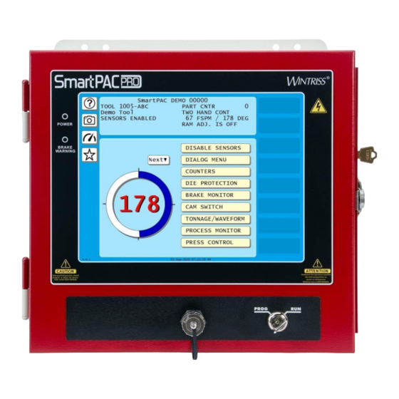
Page 26: Figure 1-1. Smartpac Pro Front Panel
SmartPAC PRO User Manual Figure 1-1. SmartPAC PRO Front Panel SmartPAC PRO is a modular interface for press automation functions including die protection and programmable cam switch. The SmartPAC PRO provides a control-reliable, brake monitor and extensive counter capabilities. SmartPAC PRO monitors and controls a variety of functions for every type of press, and can be connected to your network, enabling press operation to be monitored remotely and messages to be sent to and from the SmartPAC PRO control. -
Page 27: Smartpac Pro Standard Features
All settings are made at the operator console, using SmartPAC PRO’s touch display • Tool programs are automatically saved in SmartPAC PRO’s memory. To use the same settings when you run the job again, simply re-load your stored tool number. SmartPAC PRO can save settings for thousands of tools. •... -
Page 28: Resolver-Based Operation
Batch counters can be set to top-stop the press their presets are reached. SmartPAC PRO is able to keep an accurate parts count when multiple parts are produced on each stroke or when multiple strokes are required to produce one part.. -
Page 29: Dipropac Die Protection Module (Optional)
Refer to Chapter 2 for installation instructions and Chapter 7 for how to use ProCamPAC. SmartPAC PRO’s Modes of Operation SmartPAC PRO has three operating modes. The Main, or top, menu for each mode is shown in Figure 1-2. -
Page 30: Figure 1-2. "Top" Screen For Each Of Smartpac Pro's 3 Operating Modes
Initialization Mode (Chapter 3) Program Mode (Chapter 4) Run Mode (Chapter 5) Figure 1-2. “Top” Screen for each of SmartPAC PRO’s 3 Operating Modes Table 1-1. Initialization, Program and Run Modes: Entry and Exit Procedures Mode How to Enter This Mode... -
Page 31: Initialization Mode
Program mode. Run Mode The SmartPAC PRO is in Run mode for production. The Main Run Menu, (see Figure 1-2) shows the rotation of the crankshaft on a crank angle clock diagram in the lower left corner of the display. When the press is running in Continuous mode, the press speed in strokes per minute is displayed in the center of the clock diagram. -
Page 32: Smartpac Pro User Interface
These are described below. NOTICE You may plug a USB keyboard into the USB port on the front panel of the SmartPAC PRO. When entering alphanumeric data, the SmartPAC PRO will automatically recognize keystrokes from the on-screen keyboard/keypad and the external USB keyboard. -
Page 33: On-Screen Keyboard
Whenever you select a field that requires the input of a combination of letters, numbers, and/or symbols, SmartPAC PRO displays its on-screen keyboard. (see Figure 1-4). Backspace key clears the value. Cancel closes the numeric keypad without making any changes, and Enter accepts the value entered into the field. -
Page 34: Control And Navigation Buttons
See Dashboard button and Creating and Using Dashboards, page 36. Info button (on Dashboard screen) Press to see the SmartPAC PRO information screen which lists the press name, SmartPAC PRO serial number, firmware and hardware versions, options and other information. -
Page 35: Screen Captures
The image is saved to a USB drive plugged into SmartPAC PRO’s USB port or saved internally on the SmartPAC PRO to download or e-mail later. If no USB drive is plugged into the USB port when a screen is captured, SmartPAC PRO stores up to 25 screen captures internally. If more than 25 screens are captured, SmartPAC PRO deletes the oldest file. -
Page 36: Creating And Using Dashboards
5. Remove the USB disk. Figure 1-6. USB Transfer Complete If you attempt to download to USB disk without first plugging one into the USB Port, SmartPAC Pro displays an error (see Figure 1-7). Figure 1-7. USB Disk Error Message View Screen Capture Images on SmartPAC PRO Press and hold down the Camera button for 5 seconds. -
Page 37: Figure 1-9. Favorites Screen
1. In the Favorites screen press Edit. A red X appears on each favorite or dashboard screen, Figure 1-11. 2. Press the red X to remove each item. 3. When done, press Save. To exit without deleting any screens, press Cancel. Chapter 1 – Introduction to SmartPAC PRO... -
Page 38: Figure 1-11. Delete Screens From Favorites
2. On the Favorites Screen, press Create Dashboard. The Dashboard Configuration screen appears. Figure 1-12. Dashboard Configuration Screen 3. Press the button next to 1x2 or 2x2 to select whether to show two or four items on the dashboard. See Figure 1-13 and Figure 1-14. Chapter 1 – Introduction to SmartPAC PRO... -
Page 39: Figure 1-13. 1 X 2 Dashboard Example
Figure 1-15. Dashboard Configuration Screen, Display Area 1 Filled 5. As you populate the dashboard, press Preview to see a preview of the screen. 6. Press Done to return to the Dashboard Configuration screen. Continue configuring this dashboard, as needed. Chapter 1 – Introduction to SmartPAC PRO... -
Page 40: Figure 1-16. Dashboard Configuration Preview
7. When you are satisfied with the dashboard, press Save. Showing the Currently Selected Dashboard In any Run screen, press the Dashboard button, Figure 1-17 to display the last dashboard you selected on the Favorites screen. Figure 1-17. Dashboard Button Chapter 1 – Introduction to SmartPAC PRO... -
Page 41: Smartpac Pro Specifications
30Vdc max; Normally open – held closed. Fault condition or power off opens relay(s) Communications Connects via Ethernet to local area network; data viewed via the internet using SmartView remote viewing utility; allows backup of programmed tool settings to a network drive. Chapter 1 – Introduction to SmartPAC PRO... - Page 42 1143100 SmartPAC PRO User Manual Chapter 1 – Introduction to SmartPAC PRO...
-
Page 43: Chapter 2 - Installing Smartpac Pro
ProPAC process monitor, refer to the user manual for that option for complete details on its installation and use. This chapter describes how to install SmartPAC PRO and some of its options. It is organized in the following sections: Before You Start ..........................45 Installation Guidelines ........................ - Page 44 1143100 SmartPAC PRO User Manual Installing SmartPAC PRO as a Panel Mount ................48 Installing SmartPAC PRO in a Pendant ..................50 Installing the Resolver ........................52 Mounting the Resolver ......................54 Wiring the Resolver ........................ 54 Connecting Power Wiring – AC Powered Units ................55 Connecting Power Wiring –...
-
Page 45: Before You Start
LEARN TO USE SMARTPAC PRO BEFORE INSTALLING ON A PRESS If you have not used SmartPAC PRO before, learn how to initialize and program it before installing it on a press. On the bench, connect your unit to a resolver (Table 2-2, page 55) and to AC power (steps 1-3, page 56) so that you can access all the menus and make settings. -
Page 46: Terminating Cable Shields
NOTICE TERMINATE BOTH ENDS OF SHIELD Be sure to terminate cable shields at both ends (for example, at SmartPAC PRO and DSI 2). For each shielded cable, perform the following steps. 1. Strip the cable jacket back about 3 inches. -
Page 47: Checking The Press
Verification that the press operates and stops properly is extremely important because SmartPAC PRO will be connected to the press stop circuits. Do not forget to mark on your electrical prints where you connect SmartPAC PRO. Set the press ram to top dead center (TDC). -
Page 48: Installing Smartpac Pro As A Panel Mount
Installing SmartPAC PRO as a Panel Mount Follow the steps below to install the panel mount version of the SmartPAC PRO in your enclosure. Be sure to allow at least 6 in. (152 mm) of clearance behind the panel mounting plane to leave enough room for the electronics. -
Page 49: Figure 2-2. Smartpac Pro Panel Mount Cutout Dimension
SmartPAC PRO User Manual 1143100 Figure 2-2. SmartPAC PRO Panel Mount Cutout Dimension Chapter 2 – Installing SmartPAC PRO... -
Page 50: Installing Smartpac Pro In A Pendant
SmartPAC PRO User Manual Figure 2-3. SmartPAC PRO Panel Mount Dimensions Installing SmartPAC PRO in a Pendant To install the SmartPAC PRO display in a pendant, install the HMI board (display) in the pendant and install the RTS board in the cabinet. •... -
Page 51: Figure 2-4. Pendant Installation
Ethernet cable, ordered separately: 30 ft (7.6 m) – P/N 2315902 >16 ft (4.9 m) 50 ft (15.2 m) – P/N 2315903 100 ft (30.5 m) – P/N 2315904 Figure 2-4. Pendant Installation Chapter 2 – Installing SmartPAC PRO... -
Page 52: Installing The Resolver
Failure to comply with these instructions will result in death or serious injury. The resolver (see Figure 2-5 for dimensions) provides SmartPAC PRO with the exact position of the crankshaft at every angle throughout the stroke (see Resolver-based Operation, page 28). To deliver this precision, the resolver must be driven smoothly at a 1:1 ratio with the crankshaft. - Page 53 Failure to comply with these instructions could result in property damage. Wintriss Controls Group stocks a spring-loaded base (part# 4194300) with a hole pattern that matches the hole pattern on the resolver.
-
Page 54: Mounting The Resolver
3. Find the resolver connector TB-3 on the SmartPAC PRO board (see Figure 2-6, page 53). 4. Measure and cut the resolver wires so they comfortably reach SMARTPAC PRO. (If you run the position sensor cable through the same conduit, do not cut these wires until the position sensor is installed). -
Page 55: Connecting Power Wiring - Ac Powered Units
– clockwise or counterclockwise – as you face the resolver shaft. 8. Double-check connections when you are finished wiring. 9. Plug the L-shaped connector firmly into its receptacle on the SmartPAC PRO board. It can plug in only one way. Table 2-2. Resolver Wiring... - Page 56 75 C temperature rating is recommended for these circuits. Bring the conduit into the top right knockout of the SmartPAC PRO enclosure. Then, to wire the AC input terminal block, follow these steps: 1.
-
Page 57: Connecting Power Wiring - 24 Vdc Powered Units
Connecting Stop Circuits and Input Check Circuit You need four wires to connect SmartPAC PRO to your press control stop circuits, two for the emergency-stop circuit and two for the top-stop circuit. You can wire these circuits at your press control. -
Page 58: Making Wiring Connections
To set voltage for the input check circuit, do the following: 1. Find the input check voltage switch, S101, on the SmartPAC PRO board. It is located on the right side of the board just to the left of the E-stop relays. - Page 59 When the press control energizes the dual safety valve relay to start the press, voltage is induced across the input check circuit. If SmartPAC PRO gets no signal from the resolver within the specified start time limit (resolver not turning), SmartPAC PRO opens the emergency-stop circuit and a “loss of rotation”...
-
Page 60: Adding Or Upgrading Dipropac Or Procampac Option
Eight-, 16-, and 32-channel configurations of the same option are interchangeable. When a board is installed in the correct location, SmartPAC PRO recognizes whether it is an 8-, 16-, or 32- channel version of DiProPAC or an 8- or 16-channel version of ProCamPAC. - Page 61 SmartPAC PRO User Manual 1143100 Figure 2-11. SmartPAC PRO Main (RTS) Board Showing Location of Option Module Boards, and TB3 and TB4 CAUTION DAMAGE TO BOARD FROM STATIC DISCHARGE Ground yourself before touching circuit boards or chips by touching a large metal object such as the press.
-
Page 62: Connecting Dipro Sensor Interface To Smartpac Pro
SmartPAC PRO User Manual 7. Verify that you have installed the board(s) properly by performing the procedure in Zeroing the Resolver, page 75. You need to complete this procedure before you can use SmartPAC PRO. Connecting DiPro Sensor Interface to SmartPAC PRO NOTICE For information about using the DiProPAC, see Chapter 6 –... -
Page 63: Table 2-4. Dipro Sensor Interface (Dsi) 2 To Smartpac Pro Wiring, Sensors 1-8
SmartPAC PRO User Manual 1143100 Table 2-4. DiPro Sensor Interface (DSI) 2 to SmartPAC PRO Wiring, Sensors 1-8 1st DSI 2 (TB2) DiProPAC (TB554) Wire color* Pin # Pin Designation Pin # Pin Designation Brown SENSOR 1 SENSOR 1 SENSOR 2... -
Page 64: Table 2-5. Dipro Sensor Interface (Dsi) 2 To Smartpac Pro Wiring, Sensors 9-16
1143100 SmartPAC PRO User Manual Table 2-5. DiPro Sensor Interface (DSI) 2 to SmartPAC PRO Wiring, Sensors 9-16 2nd DSI 2 (TB2) DiProPAC (TB554) Wire color* Pin # Pin Designation Pin # Pin Designation Brown SENSOR 1 SENSOR 9 SENSOR 2... -
Page 65: Table 2-6. Dipro Sensor Interface (Dsi) 2 To Smartpac Pro Wiring, Sensors 17-24
SmartPAC PRO User Manual 1143100 Table 2-6. DiPro Sensor Interface (DSI) 2 to SmartPAC PRO Wiring, Sensors 17-24 3rd DSI 2 (TB2) DiProPAC (TB555) Wire color* Pin # Pin Designation Pin # Pin Designation Brown SENSOR 1 SENSOR 17 SENSOR 2... -
Page 66: Connecting Procampac Programmable Cam Channels
The assembly contains the relays that open and close at the angles you set in SmartPAC PRO, turning your equipment on and off. Different types of relays can be used, depending on the voltages of your equipment and any special requirements. - Page 67 To mount the ProCamPAC Output Assembly and wire it to the ProCamPAC board inside the SmartPAC PRO control, follow the instructions below. These instructions may be used with either the 8- or 16-channel ProCamPAC board. Refer to Table 2-8 and Table 2-9 for wiring connections. A wiring diagram is provided in Figure 3 at the end of the manual.
- Page 68 12-conductor cable(s) to the pin locations on the appropriate terminal blocks, as shown in Table 2-8 (for the 8-channel option) or Table 2-8 and Table 2-9 (for the 16-channel option). See also wiring diagram Figure 3 at the end of the manual. Chapter 2 – Installing SmartPAC PRO...
- Page 69 CHAN 4 CHAN 3 CHAN 2 CHAN 1 plug in standard or solid state, but not both Clearance hole Terminals for connecting wires to equipment for #6 screw (4 places) Figure 2-14. ProCamPAC Output Assembly Chapter 2 – Installing SmartPAC PRO...
-
Page 70: Table 2-8. Procampac To Cam Output Assembly Smartpac Pro01 Wiring, Cams 1-8
1143100 SmartPAC PRO User Manual Table 2-8. ProCamPAC to Cam Output Assembly SMARTPAC PRO Wiring, Cams 1-8 Wire 8-cam: ProCamPAC TB401 (cams 1-8) 1st Cam Output Board 16-cam: ProCamPAC TB451 (cams 1-8) TB301 (Pin #) (Pin #) CHAS (1) White... -
Page 71: Table 2-10. Connections To Relays
(see Figure 2-15). Suppressors are supplied with each relay. Install the suppressors across the load or as close to the load as possible. Attach suppressors by connecting leads across existing terminals or junction points. DC loads: Install a diode across each DC load, (see Figure 2-16) Chapter 2 – Installing SmartPAC PRO... - Page 72 1143100 SmartPAC PRO User Manual Figure 2-15. Installing Suppressors Across an AC Load Figure 2-16. Installing a Diode Across a DC Load Chapter 2 – Installing SmartPAC PRO...
-
Page 73: Wiring Setup Mode Circuit
Typically, the Setup mode circuit is enabled when Inch mode is selected on your clutch/brake control. When you inch the press, SmartPAC PRO will not stop the press when a fault condition is detected. The Setup mode terminal can be wired to an extra contact on the Inch position of the Stroke Select keyswitch of your press control, or you can use an external switch to activate the circuit. -
Page 74: Wiring The Procampac Output With Your Mechanical Top Stop Cam Switch (Optional)
PROGRAMMABLE CAM SWITCH NOT FOR SAFETY USE • Use SmartPAC PRO’s programmable cam switch to control auxiliary functions only. The SmartPAC PRO programmable cam capability should never be used to provide timing signals for any safety use including clutch/brake control or muting of light curtains. •... -
Page 75: Zeroing The Resolver
Verify that the press is at top dead center (i.e., at 0°± 2°) before you zero the resolver. If the press is not at TDC, your timing settings may be wrong. You must perform this procedure the first time you power up SmartPAC PRO and whenever you install a new resolver. -
Page 76: Verifying Installation Of Dipropac And/Or Procampac (Optional)
Turn off power to SmartPAC PRO, and recheck all power connections. Check that the connectors are correctly seated on both ends of the cables between the SmartPAC PRO board and the display. Power up SmartPAC PRO again. If the display remains off, contact Wintriss Tech. -
Page 77: Moving The Ram To Top Dead Center (Tdc)
If the ram is not at TDC, you must first inch the press to 0 ± 2 before you can zero the resolver. Since SmartPAC PRO is now connected to your stop circuits, you must load a tool in order to inch the press. -
Page 78: Installing The Position Sensor (Optional)
SmartPAC PRO compares the timing of this signal with the angle of the resolver. If the resolver angle changes relative to this signal, SmartPAC PRO knows that the resolver drive has slipped or broken or... - Page 79 To install the position sensor, do the following: 1. Make sure that the resolver has been zeroed (see Zeroing the Resolver, page 75). 2. Turn on power to SmartPAC PRO. 3. Turn the PROG/RUN keyswitch to PROG. The Main Program Menu displays.
- Page 80 The crankshaft angle reading should increase as you inch the press. If it decreases (359, 358, 357, for example), swap the black and yellow wires (terminals 213 and 216) on connector TB3 on the SmartPAC PRO board (see Table 2-2, page 55 and Figure 2-6, page 53). NOTICE The press must be at top dead center (0°) before the position sensor can be installed.
- Page 81 Figure 2-23. Position Sensor Installation 15. Wire the switch to SmartPAC PRO terminal block TB5 (see Table 2-11, page 73 and Figure 4 at the end of the manual). The black wire goes to terminal 247 (GND), the white or clear wire goes to terminal 246, and the red wire goes to terminal 245.
-
Page 82: Final Checkout
22. Inch the press while watching the Position Sensor LED, located beneath the Input Check Voltage Switch on the SmartPAC PRO board. Stop the press when the LED comes ON and make a note of the ON angle. Continue to inch the press until the LED goes OFF, and make a note of the OFF angle. -
Page 83: Check The Emergency-Stop Circuit
Test Complete 9. If you get to this step, SmartPAC PRO is working correctly. Clear any error messages by pressing RESET, then delete the test tool. You can now create a tool in SmartPAC PRO, program settings for it, load it, and begin to make parts using your new SmartPAC PRO. -
Page 84: Wiring Tables For Other Smartpac Pro Connections
1143100 SmartPAC PRO User Manual Wiring Tables for Other SmartPAC PRO Connections Table 2-12. SFI Port (1) and Table 2-13. Special Port (3) and Module Port (2) (TB6) Wiring Comm Test Port (4) (TB7) Wiring Pin # Signal Port Pin #... -
Page 85: Chapter 3 - Smartpac Pro Initialization Mode
This chapter shows you how to make settings in SmartPAC PRO Initialization mode. Initialization settings, which are entered via the Main Initialization Menu (see Figure 3-1), control operation of SmartPAC PRO for all tools. You make settings for individual tools in Program mode, Chapter 4. Figure 3-1. Main Initialization Menu (Includes some options. -
Page 86: Resolver Zero
NOTICE SET THE INTERNAL CLOCK IN SMARTPAC PRO When you initialize your SmartPAC PRO, be sure to set the clock to the correct date and to your local time according to the instructions in SET CLOCK, page 116. RESOLVER ZERO This item enables you to zero the resolver. -
Page 87: Position Sensor Mode
RESOLVER MOTION MODE (Normal Motion – Link Motion) (INITIALIZATION – POSITION SENSOR) This item controls whether SmartPAC PRO adapts to the action of a link-motion press. The default setting is “NORMAL MOTION.” If your SmartPAC PRO is installed on a link-motion press, for instructions go to Using SmartPAC PRO with a Link-motion Press, page 122. -
Page 88: Counter Increment Mode
“INC ALWAYS” – The Parts counter and batch counters whose increment mode is programmed as GOOD PARTS will increment on every stroke even if a fault condition is present. 2. When the setting you want is displayed, press Back. Chapter 3 – SmartPAC PRO Initialization Mode... -
Page 89: Installed Options
1143100 INSTALLED OPTIONS (INITIALIZATION – INSTALLED OPTIONS) This item enables you to view the options that are installed on your SmartPAC PRO, Figure 3-3, including the number of cam channels and sensors. Figure 3-3. Installed Options Screen Your screen will look different. -
Page 90: Options Manager
2. To enable or disable an option, press the box next to the option name to toggle between Enabled and Disabled. 3. When finished on this screen, press Apply and Restart to accept the changes. SmartPAC PRO restarts with the new settings. To leave this screen without making any changes, press Exit. You return to the Installed Options screen. -
Page 91: Press Name
PRESS NAME (INITIALIZATION – PRESS NAME) This item enables you to name the press on which SmartPAC PRO is installed. When you select PRESS NAME, the on-screen keyboard appears, allowing you to enter the press name. Press Enter when done. -
Page 92: Calculating The Stop Time Limit (Optional With Wpc 2000 Integration)
The value you set as the stop time limit on the Brake Monitor screen must factor in the normal wear on your brake to prevent SmartPAC PRO from generating stop time faults when the stopping time increases only a little. The stop time limit can be easily calculated based on the actual stopping time of your press. -
Page 93: Setting Stop Time And Start Time Limits(Optional With Wpc 2000 Integration)
You enter specific values and up to thirty characters of special information for each tool in Program and Run modes. NOTICE Tool Information screens only maintain information about the tool. They do not control any aspect of press operation. Chapter 3 – SmartPAC PRO Initialization Mode... -
Page 94: Security Access
(INITIALIZATION – SECURITY ACCESS) The SECURITY ACCESS item on the Main Initialization Menu allows you to control user access to SmartPAC PRO operating modes and settings. You set user access on the Security Access Menu, Figure 3-8. For most items on the Security Access Menu, you can specify three types of access: •... -
Page 95: Table 3-1. Security Access Settings
IF YOU FORGET OR DO NOT KNOW YOUR PASSWORD(S) Call Wintriss Tech. Support at the telephone number on the cover of this manual. Give the Tech. Support person the 5-digit number from the “Enter your password” display. In Figure 3-9, the number is “65535”. - Page 96 NO RECALC/ADJUST PASSWORD REQUIRED PROGRAM AND RUN MODES ADJUST RAMPAC PROGRAM MODE ONLY PASSWORD REQUIRED PROGRAM MODE ONLY ADJ. TOOL INFO PROGRAM AND RUN MODES PASSWORD REQUIRED INIT. PASSWORD NOT REQUIRED MUST BE USED Chapter 3 – SmartPAC PRO Initialization Mode...
-
Page 97: Setting Security Access
BE CAREFUL WHEN SETTING RESET MODE SECURITY ACCESS If you select the PROGRAM MODE ONLY or PASSWORD REQUIRED setting for the RESET MODE item, the operator will not be able to reset SmartPAC PRO in Run mode when the press stops as the result of a malfunction. -
Page 98: Backup/Restore
Figure 3-11. Backup and Restore Utility Screen This feature enables you to back up and restore tools programmed on your SmartPAC PRO. Tools may be backed up to a network drive, or, if you have ordered the USB Backup/Restore option to a USB disk inserted in the SmartPAC PRO board. -
Page 99: Backing Up Tools To A Usb Disk
The USB disk you use for backup must have at least 8 MB of free space in order to store all tools and Initialization parameters on a SmartPAC PRO. 1. Plug a USB disk with the necessary free space into USB connector on the SmartPAC PRO’s front panel 2. -
Page 100: Restoring Tools From A Usb Disk
Restoring Tools from a USB Disk NOTICE You should need to perform a restore only if the SmartPAC PRO tool and Initialization programming has been corrupted or if the SmartPAC PRO board has been replaced. The restore process overwrites programming for all your tools and Initialization settings with the tool and Initialization settings saved during the most recent backup. -
Page 101: Backup And Restore, Advanced
SmartPAC PRO User Manual 1143100 2. Press Restore. The tool information is restored to the SmartPAC PRO from the network folder. “Restore Completed” appears below the screen title. 3. Press Exit to return to the Main Initialization Menu. Backup and Restore, Advanced (INITIALIZATION –... -
Page 102: Setup Data Comms/Sfc (Optional)
Key in the value on the onscreen keypad. Press Enter. PERSIST DIALOG Press Enter. Press Enter to toggle between ENABLED and DISABLED. AUTO BACKFILL Press Enter. Press Enter to toggle between ENABLED and DISABLED. Chapter 3 – SmartPAC PRO Initialization Mode... - Page 103 Press Enter. Key in the Screen Mode is 16/16) name or sequence. Press Enter. Note: To clear all the names and values, press CLEAR ALL. Press Back when done. Chapter 3 – SmartPAC PRO Initialization Mode...
-
Page 104: Entering Special Names And Sequence Numbers
5. Press ENTER. Key in the name or sequence number on the onscreen keyboard. 6. Press Enter. 7. When finished entering special names and sequence numbers, press Back to return to the Set Communications menu. Chapter 3 – SmartPAC PRO Initialization Mode... -
Page 105: Entering Sequence Numbers For Canned Names
1. Press the () arrows to select SET CANNED NAMES. 2. Press ENTER. The Dialog Fixed Name Choice Menu screen appears. 3. Press the () arrows to highlight the number next to a canned name on the list. Chapter 3 – SmartPAC PRO Initialization Mode... -
Page 106: Setup Network
SETUP NETWORK (INITIALIZATION – SETUP NETWORK) NOTICE Your network administrator must connect SmartPAC PRO to your network before you can use e- mail messaging or SmartView remote viewing utility. For e-mail, your network must have a valid SMTP mail server. -
Page 107: Setup Email
SmartPAC PRO’s E-mail function allows you to send e-mails to individuals in your SmartPAC PRO network and to other recipients, such as Wintriss Tech. Support, via the Internet. If you plan to use E- mail, follow the instructions below. If you need information about your network, contact your IT department. -
Page 108: Setting Up The Recipient List
6. Press Add. The name and e-mail address are added to the recipients list. 7. When you are done entering names and e-mail addresses, press Save. 8. Press Exit to return to the Main Initialization Menu. Figure 3-20. E-mail Recipients Chapter 3 – SmartPAC PRO Initialization Mode... -
Page 109: Entering Predefined Messages
4. Press Add. The message is added to the recipients list. 5. When you are done entering names and e-mail addresses, press Save. 6. Press Exit to return to the Main Initialization Menu. Chapter 3 – SmartPAC PRO Initialization Mode... -
Page 110: Info Center
SMARTVIEW FUNCTION (INITIALIZATION – SETUP NETWORK – ENABLE SMARTVIEW) SmartPAC PRO’s SmartView function enables individuals on your network to remotely view the status of each press. If you plan to use SmartView, do the following to enable this function: 1. Press the box next to ENABLE SMARTVIEW so it is checkmarked. -
Page 111: Press Type
Your entry for the PRESS TYPE item is used by the SmartView remote viewing to select the graphic it uses to illustrate the type of press (i.e., straight side or gap frame) on which SmartPAC PRO is installed. This graphic appears in the press information summary on the SmartView Main Page. - Page 112 2. Press to check the boxes of the faults to prohibit from remote reset. To see additional faults, scroll down using the scroll bar at the right of the list. 3. When finished, press Apply Changes. 4. Press Back to return to the Network Setup Utility screen. Chapter 3 – SmartPAC PRO Initialization Mode...
-
Page 113: Change Network Settings
(INITIALIZATION – SETUP NETWORK - CHANGE) Figure 3-25. Change Network Settings: Local Area Connection This item is for use by your Information Technology or Information Systems person. Call Wintriss Tech. Support for assistance in making advanced network settings. In the Network Setup Utility screen press CHANGE. The Network Settings Local Area Connection screen appears. -
Page 114: Diagnostics
(INITIALIZATION – DIAGNOSTICS) The DIAGNOSTICS item on the Main Initialization Menu gives you access to the Diagnostics Menu, Figure 3-26, which you use primarily when you are working with Wintriss Tech. Support for initial setup or troubleshooting. Figure 3-26. Diagnostics Menu This section documents only the following items: •... -
Page 115: Communications
Viewer screen, shown in Figure 4-20, displays. Figure 4-20. Communications Data Viewer Screen This screen allows you to verify communications between SmartPAC PRO and its installed modules, including SFI and WPC. Press the button at upper right to toggle between COMBINED TX AND RX and SPLIT TX AND RX. -
Page 116: Set Clock
To stop the clock, press STOP THE CLOCK. The label changes to START THE CLOCK. To restart the clock, press START THE CLOCK. 4. Press Back when you are done to return to the Diagnostics Menu. Chapter 3 – SmartPAC PRO Initialization Mode... -
Page 117: Save To Usb Disk
This item enables you to save the error/event log, screen captures, and other data maintained in a special SmartPAC PRO buffer to a USB disk. Once the data has been saved, you can remove the USB disk, transfer the information to a computer, and e-mail it to Wintriss Tech. Support or to another recipient. -
Page 118: System Init
Figure 3-27. Initialize SmartPAC System Screen Follow the instructions in the sections below for • Reset Initialization Data, next section, to clear initialization data from SmartPAC PRO and modules. • Application Data Menu, page 120, to delete tools, dashboards, favorites and/or screen captures •... - Page 119 OK. A warning window appears, Figure 3-30. 6. Press OK to clear the initialization data. To exit without clearing the data, press Cancel and the screen returns to the Main Initialization Menu. Chapter 3 – SmartPAC PRO Initialization Mode...
-
Page 120: Application Data Menu
4. Press Delete Selected Tools. A warning box appears, Figure 3-32. • If you want to delete the selected tools, press Yes. • If you do not want to delete the selected tools, press No. Chapter 3 – SmartPAC PRO Initialization Mode... -
Page 121: Delete All Dashboards, Favorites, Or Screen Captures
• If you want to delete the items, press Yes. • If you do not want to delete the items, press No. 4. Press Back to return to the Main Initialization Menu. Chapter 3 – SmartPAC PRO Initialization Mode... -
Page 122: Disable Loss Rotation
Press Disable Loss Rotation to prevent loss-of-rotation errors. Using SmartPAC PRO with a Link-motion Press If your SmartPAC PRO is installed on a link-motion press, you need to determine whether to use NORMAL MOTION or LINK MOTION for your RESOLVER MOTION MODE setting (see page 87) and, if you are using a servofeed with a Wintriss ServoFeed Interface (SFI), how to compensate for the different upstroke and downstroke speeds on your link-motion press. -
Page 123: Using A Servofeed Interface With Link Motion
Using a ServoFeed Interface with Link Motion If you have a link-motion press and are using a servofeed with a Wintriss Servofeed Interface (SFI), you can compensate for the change in speed between the upstroke and downstroke. In a link-motion press, the upstroke is substantially faster than the downstroke, the downstroke being slowed to improve forming operations. -
Page 124: Press Speed Compensation For Link Motion
Advisor by 3%, and calculate a new value with this setting (see steps 2 and 3). Load the tool number, and run the press to observe the feeding again. Continue to decrease Press Speed in the Feed Advisor by 3% increments until feeding is complete at the correct time. Chapter 3 – SmartPAC PRO Initialization Mode... -
Page 125: Chapter 4 - Smartpac Pro Program Mode
Chapter 4 – SmartPAC PRO Program Mode This chapter shows you how to make settings in SmartPAC PRO Program mode. The Program Mode settings - which are entered via the Main Program Menu (see Figure 4-1) - control SmartPAC PRO operation for an individual tool. -
Page 126: Tool Manager
To see a detailed summary of the tool data, such as counter presets, cams and sensors, go to Viewing Tool Data Summary, page 131. Chapter 4 – SmartPAC PRO Program Mode... - Page 127 SmartPAC PRO User Manual 1143100 Figure 4-3. Tool Manager List View Figure 4-4. Tool Manager List View, Tool Detail Loaded tool highlighted in yellow; detail shown for tool highlighted in green. Chapter 4 – SmartPAC PRO Program Mode...
-
Page 128: Creating A New Tool
3. The new tool will now appear in the Tool Manager, but will have no settings associated with it. Before you can load and run this setup, you must program settings for this tool. See Tool Program Menu, page 133. Figure 4-5. Tool Manager Screen with Numeric Entry Window Chapter 4 – SmartPAC PRO Program Mode... -
Page 129: Copying An Existing Tool
Tool Template is not used to run the press. NOTICE PASSWORD PROTECTION FOR TOOL TEMPLATE To prevent unauthorized changes, you can set SECURITY ACCESS, page 94, so that a password is required to change the Tool Template. Chapter 4 – SmartPAC PRO Program Mode... -
Page 130: Loading A Tool
If an error message displays, go to Chapter 8 and follow the instructions for correcting the problem. • If the error is not covered in Chapter 8, or you cannot fix the problem, call Wintriss Tech. Support. Changing Settings for a Loaded Tool (PROGRAM –... -
Page 131: Deleting A Tool
2. Scroll down as needed to see the whole summary, which may include • counter and preset information. • die protection sensor information (if DiProPAC option installed) • programmable cam information (if ProCamPAC option installed) Chapter 4 – SmartPAC PRO Program Mode... - Page 132 1143100 SmartPAC PRO User Manual • press control parameters (if SmartPAC PRO is integrated with WPC 2000) • tonnage monitor information (if a tonnage monitor option is installed) Adding a Note to the Tool Data Summary Figure 4-10. Tool Data Summary Screen, Scrolled to Bottom At the bottom of the screen, to which you may need to scroll down, you can enter additional information in the Tool Notes area, Figure 4-10.
-
Page 133: Tool Program Menu
This item on the Tool Program Menu allows you to assign a name to a tool. To do so, perform the following steps: 1. On the Tool Program Menu, press TOOL NAME. The on-screen keyboard appears, Figure 4-12. Chapter 4 – SmartPAC PRO Program Mode... - Page 134 Secondary counters called “Batch Counters” can initiate various actions when a preset number of strokes has been reached. Settings are made via the Counters screen, Figure 4-13. Figure 4-13. Counters Screen Chapter 4 – SmartPAC PRO Program Mode...
- Page 135 Top Stop, Toggle, or Pulse. When a Batch counter is set to TOP STOP, SmartPAC PRO top-stops the press and displays a message, as it does for Strokes and Good Parts counters. This setting is useful when stopping the press to change bins before resuming production.
- Page 136 Setting Preset Values Counter presets specify the count at which SmartPAC PRO initiates one of three programmed actions (i.e., Top-stop, Toggle, or Pulse). To enter counter presets, do the following: 1. On the Tool Program Menu, select COUNTERS to display the Counters screen.
- Page 137 OUTPUT MODE column for the Batch counter you want to program, then press ENTER to toggle among the three options (i.e., TOP STOP, TOGGLE, and PULSE) until the setting you want is displayed. Chapter 4 – SmartPAC PRO Program Mode...
-
Page 138: Setting Counter Increment Angle
Setting Parts per Stroke or Strokes per Part SmartPAC PRO allows you to control how the Strokes and Good Parts counters increment in relation to each other. You can specify the number of parts made during each stroke, in which case the Good Parts counter will increment in multiple units (e.g., 2, 3, etc.) for each increment of the Strokes... - Page 139 2. Key in a pre-load count value and press ENTER. The value you keyed in displays on the Advanced Counter Mode Selections screen. 3. Make sure that the AUTO BATCH PRE-LOAD field is set to OFF. 4. Press Exit to return to the Counter Mode Selections screen. Chapter 4 – SmartPAC PRO Program Mode...
-
Page 140: Die Protection (Optional)
These limits apply to all operating modes - Continuous, Single-stroke, and Inch. When the speed of the press exceeds the maximum limit, SmartPAC PRO stops the press and displays the fault message “Maximum press speed exceeded.” When press speed drops below the minimum limit, SmartPAC PRO stops the press and displays the fault message “Minimum press... -
Page 141: Tool Information
The value you enter in the MAXIMUM PRESS SPEED field must be greater than the Minimum Press Speed value. If the Maximum Speed setting is less than or equal to the Minimum Speed value, SmartPAC PRO changes the Maximum Speed to one Stroke per Minute greater than the Minimum Speed. - Page 142 1143100 SmartPAC PRO User Manual Chapter 4 – SmartPAC PRO Program Mode...
-
Page 143: Chapter 5 - Smartpac Pro Run Mode
Selecting Attachments ....................158 Sending the Message ...................... 158 This chapter shows you how to use the SmartPAC PRO in the Run mode, which is the mode you select to run production. Instructions include how to adjust settings for individual tools and monitor press parameters such as speed and sensor status. -
Page 144: Entering And Exiting Run Mode
To switch to Program mode: Turn the PROG/RUN keyswitch to RUN.* Turn the PROG/RUN keyswitch to PROG.* * If you turn the key and nothing happens, press Reset, Exit, or Back repeatedly until SmartPAC PRO changes modes. Chapter 5 – SmartPAC PRO Run Mode... -
Page 145: Settings Locked Or Password Required
To view the multiple errors, press DISPLAY ALL ERRORS. A large red message window opens, as shown in Figure 5-3, with each fault listed in sequence beneath the caption “ALL PENDING ERRORS.” To close the window, press EXIT. Chapter 5 – SmartPAC PRO Run Mode... -
Page 146: Disable (Enable) Sensors (Optional)
If it is labeled DISABLE SENSORS, press to enable sensors. • If it is labeled ENABLE SENSORS, press to disable sensors. When sensors are disabled, “SENSORS DISABLED” flashes red in the status box at the top of the screen. Chapter 5 – SmartPAC PRO Run Mode... -
Page 147: Counters
Pre-load values display in the Count field for the batches you have programmed with those values. When messages display indicating that counter presets have been reached, Press Reset to clear the message. See Counter Preset Reached Messages, page 224. Chapter 5 – SmartPAC PRO Run Mode... -
Page 148: Die Protection (Optional)
Failure to comply with these instructions will result in death or serious injury. SmartPAC PRO’s built in Brake Monitor enables you to view your press’s starting time, stopping time, and stopping angle and perform the 90 stop-time test to determine the longest stopping time of the press. -
Page 149: Determining The Stopping Time Of Your Press
Starting time is the time it takes for the crankshaft to start turning after the DSV has been energized. Instructions for setting start time and stop time limits and documentation of SmartPAC PRO’s responses to start time and stop time faults are provided in SET BRAKE MONITOR (Optional with WPC 2000 Integration), page 91. -
Page 150: Performing The 90 Stop-Time Test
90 DEGREE BRAKE TEST ARMED PRESS EXIT TO CANCEL TEST 5. When SmartPAC PRO emergency-stops the press, which occurs the next time the press reaches 90, record the number in the 90 STOP TIME VALUE (MSEC) field on the Stop Time Status screen. -
Page 151: Press Speed
Inch. Adjustments are made on the Press Speed Parameters screen, shown in Figure 5-7. Figure 5-7. Press Speed Parameters Screen When the speed of the press exceeds the maximum speed limit, SmartPAC PRO stops the press and displays the fault message “Maximum press speed exceeded.” When press speed drops below the minimum speed limit, SmartPAC PRO stops the press and displays the fault message “Minimum... - Page 152 The value you enter in the MAXIMUM PRESS SPEED field must be greater than the Minimum Press Speed value. If the Maximum Speed setting is less than or equal to the Minimum Speed value, SmartPAC PRO changes the Maximum Speed to one Stroke per Minute greater than the Minimum Speed.
-
Page 153: Tool Information
When a new tool is loaded, the log displays the tool number. If SmartPAC PRO is connected to a computer network and e-mail is enabled, the log also shows messages sent by SmartPAC PRO. When SmartPAC PRO is networked, you can send the Error/Event Log to Wintriss Tech. -
Page 154: Load New Tool
The LOAD NEW TOOL menu selection enables you to load a new tool when the press is stopped. (You cannot load a new tool when the press is running. If you attempt to do so, SmartPAC PRO will display an error message, indicating that the press must be stopped before a tool can be loaded.) When you select LOAD NEW TOOL, the Tool Manager screen, shown in Figure 5-10, displays. - Page 155 If an error message displays, go to Chapter 8 and follow the instructions for correcting the problem. If the error is not covered in Chapter 8, or you cannot fix the problem, call Wintriss Tech. Support. Chapter 5 – SmartPAC PRO Run Mode...
-
Page 156: Messaging
1. On the Run menu press Messaging. The Messaging screen appears, Figure 5-12. If you want to stay in the Messaging screen after sending, uncheck the box labeled Exit after send. Figure 5-13. Select Recipients 2. Press To:. The Select Recipients window opens, Figure 5-13. Chapter 5 – SmartPAC PRO Run Mode... -
Page 157: Selecting Message
If you selected a predefined message, you are returned to the Messaging screen. • If you selected Custom Message, key in the message on the onscreen keyboard and press Done to return to the Messaging screen. Then, press okay. Chapter 5 – SmartPAC PRO Run Mode... -
Page 158: Selecting Attachments
Selecting Attachments Figure 5-15. Select Attachments Window 8. If you want to attach one file stored on SmartPAC PRO, such as a screen capture or error log entry, press Attach:. A window opens showing the available files. 9. Press the file you want to attach. -
Page 159: Chapter 6 - Using Dipropac Die Protection (Optional)
Setting the Sensor Stop Type ....................185 Setting the Critical Angle for a Sensor Set to SMART STOP ..........186 Setting the Ready Signal for a Green Sensor ................ 188 SmartPAC PRO User Manual 1143100 Chapter 6 – Using DiProPAC Die Protection (Optional) - Page 160 • “Copy a Sensor” button added When configured with the DiProPAC option, SmartPAC PRO can monitor up to 32 sensors, to detect malfunctions such as stock buckling, misfeeds, and improper part ejection. Set timing for sensor inputs (DiProPAC Only). You can specify how you want installed sensors to monitor press operation.
-
Page 161: Dipropac In Initialization Mode
DiProPAC in Initialization Mode The following sections show you how to use the selections available on the Main Initialization Menu to set initialization parameters for SmartPAC PRO with DiProPAC. Sensor Names DiProPAC provides twelve preset sensor names for you and allows you to create as many custom sensor names as you need. -
Page 162: Entering Global Sensor Names
1143100 SmartPAC PRO User Manual Entering Global Sensor Names In Initialization mode, you can create a “global” list of sensor names available to all your tools. In Program mode, you can create sensor names used only with individual tools, or add them to the global sensor name list. - Page 163 SmartPAC PRO User Manual 1143100 2. To add a new global sensor name, press NEW ENTRY. An entry keyboard appears, Figure 6-3. Figure 6-3. Entry Keyboard for Global Sensor Name 3. Key in the sensor name you want, as in Figure 6-4. Press Enter when done. The Global Sensor Names screen appears, showing the name you added, Figure 6-5.
-
Page 164: Sensor Enable Mode
1143100 SmartPAC PRO User Manual Figure 6-5. Global Sensor Names Screen Showing Name Added Repeat these steps to add the other global sensor names you want to use, up to the number of sensor channels in your DiProPAC (8, 16 or 32). -
Page 165: Selecting Sensor Enable Mode
This mode, as its name indicates, is used during setup. You enable Setup mode by selecting the Inch setting with the Stroke Select keyswitch on the front panel of the SmartPAC PRO. NOTICE To enable Setup mode, your Stroke Select keyswitch must be wired to the Setup mode input, terminal #252 on TB5 (see Wiring Setup Mode Circuit, page 73). -
Page 166: Dipropac Die Protection In Program Mode
1143100 SmartPAC PRO User Manual DiProPAC Die Protection in Program Mode (PROGRAM – TOOL MANAGER – Select Tool – EDIT TOOL – DIE PROTECTION) Figure 6-7. Main Program Menu for a Tool This item appears on the Tool Program Menu only when DiProPAC is installed. It enables you to program up to 8, 16, or 32 die protection sensors. -
Page 167: Selecting Sensor Enable Mode By Tool In Program Mode
SmartPAC PRO User Manual 1143100 Figure 6-9. Die Protection Sensor Menu for Tool 1063, Sensors 16-32 (DiProPAC 32-sensor option shown. Your unit may not have this screen.) Selecting Sensor Enable Mode by Tool in Program Mode The sensor enable mode setting you make in initialization (SENSOR ENABLE MODE, page 164) applies to all the sensors on all the tools. -
Page 168: Understanding Sensor Terminology
The die can be damaged if these events do not occur at the proper angle. The Ready Signal is a timing signal you specify for a sensor to tell the SmartPAC PRO when to expect that sensor to actuate. -
Page 169: Static Sensors: Yellow And Red Sensors
Because these sensors operate independently of the crankshaft, you do not set a Ready signal for them. Yellow Sensors Yellow sensors are normally open. When a yellow sensor closes (actuates), SmartPAC PRO sends a Stop command to the press. Red Sensors Red sensors are normally closed (actuated). -
Page 170: Bypass Angle (Static Sensors)
In such cases, you can program the optional Bypass Angle for Yellow and Red sensors. During the bypass, SmartPAC PRO ignores the sensor, so any fault during that window will not cause a nuisance stop. During the rest of the stroke, SmartPAC PRO monitors the sensor normally. -
Page 171: Cyclic Sensors: Green Sensors
Examples are part ejection, stock feed, and part transfer. SmartPAC PRO stops the press if a green sensor fails to actuate during its Ready Signal, or if it actuates at the wrong time. Chapter 6 – Using DiProPAC Die Protection (Optional) -
Page 172: Standard Green Sensors
SETTING INDEPENDENT READY SIGNALS FOR GREEN SENSORS. Previous versions of SmartPAC PRO placed limitations on the setting of ready signals for sensors 17- 32. This is no longer the case. You can give each sensor a different ready signal if you like. -
Page 173: Green Quick Check Sensors
SmartPAC PRO User Manual 1143100 Green Quick Check Sensors A “green quick check” sensor must actuate during the Ready signal and only during the Ready signal. In other words, the sensor must turn on and turn off within the Ready signal. -
Page 174: Green Special Sensors
Green Special sensor input for a five-stroke window. If no slugs are ejected after five strokes, SmartPAC PRO sends a Stop command to the press. In some applications, you need to delay the monitoring of a Green Special sensor upon startup. For example, when a sensor is using the green special sensor type to monitor parts or slugs coming out of the press on a conveyor. -
Page 175: Green Flex Sensors
SmartPAC PRO User Manual 1143100 Green Flex Sensors The Green Flex Sensor is a versatile cyclic sensor monitoring type. In addition to the standard green (cyclic) sensor requirements – i.e. it must turn on sometime during the ready signal and turn off somewhere outside the ready signal –... -
Page 176: Masking
1143100 SmartPAC PRO User Manual progression, you can set the sensor to be a Green Flex, set the number of required pulses to 4, and set it so that it “Must be ON” at the end of the ready signal. -
Page 177: Programming Sensor Settings
SmartPAC PRO User Manual 1143100 Figure 6-18. Sensor Program Screen showing the Masking feature disabled (default setting) Figure 6-19. Standard Green Sensor Type with Masking Enabled. This sensor will check for part ejection every fourth stroke. Programming Sensor Settings Setting Enable Mode In initialization you may have set a global enable mode that applies to all tools, Entering Global Sensor Names, page 162. -
Page 178: Copy A Sensor
1143100 SmartPAC PRO User Manual • AUTO BY TOOL – All sensors for this tool are enabled after the number of strokes you specify • AUTO BY SENSOR – Each sensor is enabled after the number of strokes you set for it. -
Page 179: Naming The Sensor
SmartPAC PRO User Manual 1143100 Figure 6-21. This Tool’s Previously Programmed Sensors from Which You Can Copy the Timing and Stop Type On the Die Protection Sensor Menu, you select a sensor to program and then enter settings for the sensor: name, sensor type, stop type, and, if applicable, ready window or special count. - Page 180 1143100 SmartPAC PRO User Manual 2. Press the tool you want to program to highlight it. Press EDIT TOOL. The Tool Program screen appears. 3. Press DIE PROTECTION. The tool’s sensor list appears. Figure 6-22. Sensor List for a Tool 4.
- Page 181 SmartPAC PRO User Manual 1143100 5. Key in the sensor name you want, up to 20 characters. Press Enter. A confirmation window opens (Figure 6-25). Figure 6-24. New Sensor Name Entry Keyboard 6. The confirmation window asks if you would like to add the new name to the global sensor name list.
-
Page 182: Setting The "Auto Enable By Tool" Counter Value
ENABLE COUNTER field. 4. Press the button for the sensor you want to program. • If that sensor has not been programmed, SmartPAC PRO walks you through the programming steps as described in the following sections. • If that sensor has already been programmed, the Sensor Program screen appears, Figure 6-27. -
Page 183: Setting The Stroke Count For Auto Enable By Sensor
SmartPAC PRO User Manual 1143100 Figure 6-27. Sensor Program Screen (for Previously Programmed Sensors) Setting the Stroke Count for Auto Enable by Sensor After you enter a sensor name, if Sensor Enable Mode is set to AUTO BY SENSOR in Initialization (see page 164), the Auto Enable by Sensor Stroke Count screen displays, Figure 6-28. -
Page 184: Setting Sensor Type
1143100 SmartPAC PRO User Manual 2. Key in the value you want (maximum is 99) and press Enter. This saves the number of strokes value you entered. The Sensor Type screen appears; see next section. Setting Sensor Type After you select a sensor name and, if AUTO ENABLE BY SENSOR is the Initialization setting, specify the Auto Enable stroke count, the Sensor Type screen, Figure 6-29, displays with the name you selected for the sensor shown at the right of the Status Box beneath the sensor number. -
Page 185: Setting The Sensor Stop Type
• Top Stop: SmartPAC PRO stops the press at the top of its stroke after a sensor fault is detected. You should use this setting for events that do not threaten the die or that occur between the critical angle and bottom dead center (BDC). -
Page 186: Setting The Critical Angle For A Sensor Set To Smart Stop
Setting the Critical Angle for a Sensor Set to SMART STOP When you program a sensor for a Smart Stop, you must also set the critical angle SmartPAC PRO uses to determine whether an Emergency Stop or Top Stop command is sent to the press. The critical angle you program for the first sensor set to Smart Stop is used as the critical angle for all sensors set to Smart Stop for that tool. - Page 187 SmartPAC PRO User Manual 1143100 Figure 6-31. Critical Angle Programming Screen NOTICE The Critical Angle default of 185° cannot be used as your Smart Stop critical angle setting. If you attempt to enter 185° as the critical angle, a window will open, asking you to enter a different value.
-
Page 188: Setting The Ready Signal For A Green Sensor
1143100 SmartPAC PRO User Manual Setting the Ready Signal for a Green Sensor After you select the stop type for a Green, Green Quick Check, Green Constant, or Green Flex sensor, the Ready Signal Programming screen displays, Figure 6-32. The Ready signal is the timing window during which the sensor must actuate to prevent SmartPAC PRO from sending a stop signal to the press. -
Page 189: Setting The Counter Value For A Green Special Sensor
SmartPAC PRO User Manual 1143100 Setting the Counter Value for a Green Special Sensor When you select GREEN SPECIAL as the sensor type, the Green Special Sensor Stroke Count screen displays, Figure 6-33. On this screen, you set the number of strokes that the press can make before the Green Special sensor must actuate. -
Page 190: Viewing And Changing Sensor Settings
1143100 SmartPAC PRO User Manual Viewing and Changing Sensor Settings When you finish making settings for a sensor, you are taken to a screen like the one shown in Figure 6-34, which displays all the settings for the sensor. Figure 6-34. Sensor Program Screen This screen is also displayed whenever you select a previously programmed sensor on the Die Protection Sensor Menu. -
Page 191: Viewing The Sensor Summary
SmartPAC PRO User Manual 1143100 Viewing the Sensor Summary You can view a summary of the settings that have been made for all programmed sensors shown on the Die Protection Sensor Menu, including the critical angle that has been set for the tool. To view the summary, do the following: On the Die Protection Sensor Menu, press VIEW SENSOR SUMMARY. -
Page 192: Sensor Enable/Disable & Status
SENSORS. 3. Press Back to return to the Main Program Menu. NOTICE When a tool is loaded, or when SmartPAC PRO is powered up, all programmed sensors are turned on and enabled. Chapter 6 – Using DiProPAC Die Protection (Optional) -
Page 193: Enabling Or Disabling All Sensors
When the message is SENSORS ENABLED, SmartPAC PRO is communicating with all the sensors that are programmed and turned on. When the message is SENSORS DISABLED, SmartPAC PRO is not communicating with the sensors. -
Page 194: Run Mode
1143100 SmartPAC PRO User Manual Run Mode DISABLE (ENABLE) SENSORS NOTICE DiProPAC has an optional “sensors disabled” output that turns on when the sensors are disabled. See Wiring a Sensor-Disabled Output (Optional), page 73. This item allows you to manually enable your sensors when they are disabled, or to disable your sensors when they are enabled. - Page 195 SmartPAC PRO User Manual 1143100 Sensor, page 183, to make the appropriate setting for the tool. Figure 6-39. Disable Sensors Confirmation Message In order to protect the tool, sensors should always be enabled except during setup and troubleshooting when they can be temporarily disabled. You can wire (see Wiring Setup Mode Circuit, page 73) and enable (see Enabling Setup Mode, page 165) a setup mode circuit that allows you to run the press in Inch during setup with green sensors disabled.
-
Page 196: Adjusting The Ready Signal For Green Sensors
1143100 SmartPAC PRO User Manual Figure 6-40. Sample Die Protection Run Mode Menu (Your menu will look different) Adjusting the Ready Signal for Green Sensors When you select a green, green quick check, or green constant sensor on the Die Protection Menu, the Ready Signal Programming screen, shown in Figure 6-41, displays. - Page 197 SmartPAC PRO continuously displays 190 as the sensor’s On value. However, if the On angle changes to 189, SmartPAC PRO displays the On angle as 189 on the next stroke. To clear the actuation angles displayed for a sensor, press UPDATE THE SENSOR ARC. If the press is stopped, the Sensor window displays zeros.
-
Page 198: Adjusting The Stroke Preset For Green Special Sensors
1143100 SmartPAC PRO User Manual NOTICE To update the sensor’s On/Off readings, press UPDATE THE SENSOR ARC. To change the reference angle from 0°to 180°, press the Chg Reference Angle button. The reference angle is used to determine earliest and latest On/Off readings. -
Page 199: Viewing Sensor Status
SmartPAC PRO User Manual 1143100 Viewing Sensor Status You can view the current state of all your sensors by pressing SHOW SENSOR STATUS to display the Sensor Status screen, shown in Figure 6-43. Figure 6-43. Sensor Status Screen The Sensor Status screen shows the status of every sensor for a loaded tool. Sensor inputs are identified by the numbers. - Page 200 1143100 SmartPAC PRO User Manual Chapter 6 – Using DiProPAC Die Protection (Optional)
-
Page 201: Chapter 7 - Using Procampac Programmable Cams
Remember that they are options and might not be included in your system. If you ordered SmartPAC PRO with other optional modules such as AutoSetPAC load monitor or ProPAC process monitor, refer to the user manual for that option for complete details on its installation and use. -
Page 202: Procampac Programmable Cam Switch
Refer to Chapter 2 for details on wiring the cam channels. The AC power supply wires to SmartPAC PRO should be run separately from the DC control wires going to the ProCamPAC Output Assembly. Never use the SmartPAC PRO power terminals as a junction point to provide power for external devices. - Page 203 SmartPAC PRO User Manual 1143100 Figure 7-1. Cam Channel Name Menu Your display may look different. 2. Select a channel using the cursor keys and press ENTER. The screen showing a list of names appears, Figure 7-2. Press and move the scroll bar at the right of the list to see additional names.
-
Page 204: Auto Advance And Slow Rpm (Procampac)
You must also specify the minimum press speed at which auto advance will be applied. This value is entered in the SLOW RPM field on the Auto Advance Menu. SmartPAC PRO uses the Slow RPM value as a starting point in the auto advance process. If the value you enter for Slow RPM is... -
Page 205: Calculating The Auto Advance Constant
SmartPAC PRO User Manual 1143100 press is running. When the press is stroking, the press speed in SPM is displayed in the upper right corner of the screen under the caption PRESS SPEED. When an Auto Advance cam is turned on, the press angle is displayed in the same location under the caption PRESS ANGLE. -
Page 206: Set Global Cams (Optional)
NOTICE AUTO ADVANCE IS ADJUSTABLE SmartPAC PRO allows you to adjust Auto Advance and Slow RPM settings in Initialization mode while the press is running. The angle at which an Auto Advance cam turns on is shown in the upper right corner of the screen under the caption PRESS ANGLE, enabling you to see the effect of different settings. - Page 207 SmartPAC PRO User Manual 1143100 Figure 7-4. Global Cams Menu Asterisk (*) Indicates Global Cams 1. Select the cam you want to program. The Global Cam Timing Type screen displays, Figure 7-5. Figure 7-5. Global Cam Timing Type Screen 2. Select the type of cam timing you want to program for this channel, referring to Run Mode: CAM SWITCH (ProCamPAC), page 218 for instructions.
-
Page 208: Procampac In Program Mode
1143100 SmartPAC PRO User Manual ProCamPAC in Program Mode NOTICE BATCH COUNTERS AND PROCAMPAC See the Program chapter Batch counters, page 135, for the effect batch counter settings for PULSE or TOGGLE have on the cams. Figure 7-6. Program Menu... -
Page 209: Programmable Cam Switch (Procampac)
PROGRAMMABLE CAM SWITCH NOT FOR SAFETY USE Use SmartPAC PRO’s programmable cam switch to control auxiliary functions only. The SmartPAC PRO programmable cam capability should never be used to provide timing signals for any safety use including clutch/brake control or muting of light curtains. -
Page 210: Making An On/Off Setting
1143100 SmartPAC PRO User Manual Figure 7-8. Cam Channel Program Type Menu Instructions for programming cam channels using each of the program types shown on the Cam Channel Program Type Menu are provided in the following sections. Making an ON/OFF Setting The PROGRAM ON/OFF ANGLES item on the Cam Channel Program Type Menu enables you to program the crankshaft angles at which a selected cam channel turns on and off. -
Page 211: Setting Multiple On/Off Cycles
4. Press Back when you are finished to return to the Cam Channel Program Type Menu. Setting Multiple ON/OFF Cycles SmartPAC PRO with ProCamPAC enables you to set more than one On/Off event (or cycle) for selected cam channels. You can program up to four On/Off events for a single channel. - Page 212 1143100 SmartPAC PRO User Manual 2. Press ADD A NEW ARC on the Cam Channel On/Off Program screen to program a second On/Off cycle. The arc you set in step 1 (i.e., Arc 1) turns dark gray. You can program a new arc, initially set at on and off at 0°.
-
Page 213: Making A Timed Output Setting
SmartPAC PRO User Manual 1143100 Figure 7-12. Cam Channel On/Off Program Screen: Three On/Off Arcs Making a Timed Output Setting The PROGRAM TIMED OUTPUT item on the Cam Channel Program Type Menu enables you to program the crankshaft angles at which a selected cam channel turns On and the time, or dwell, in milliseconds that the channel stays On. -
Page 214: Making An Auto Advance Setting
1143100 SmartPAC PRO User Manual Figure 7-13. Cam Channel Timed Output Program Screen NOTICE FOR APPLICATIONS REQUIRING MORE THAN 500 MILLISECONDS If you have an application where an On time of more than 500 milliseconds is required, do the following. Program one of the batch counters to a preset of “1,” set the Counter Increment Angle to the desired On angle and the Output Mode to PULSE. -
Page 215: Setting Dsv On Channel Timing
SmartPAC PRO User Manual 1143100 2. Set the AutoOn angle on the crank angle clock, using the plus and minus buttons (+/–) for Channel Timing On. The precise AutoOn angle value is displayed in the window inside the clock display. In Figure 7-14, the AutoOn angle is set to 260. -
Page 216: Deleting Channel Settings
1143100 SmartPAC PRO User Manual Figure 7-15. Cam Channel DSV On Program Screen To set the DSV delay time, do the following: 1. Select PROGRAM DSV ON on the Cam Channel Program Type Menu. The Cam Increment or decrement the OFF DELAY TIME value (maximum is 254 seconds), using the Up () or Down () cursor button. -
Page 217: Viewing The Cam Summary
Global cams, which are programmed in Initialization mode (see SET GLOBAL CAMS (Optional), page 206), are cam channels that can be used with any tool set up on your SmartPAC PRO. Global cams can be programmed for any channel except channels 6, 7 and 8 and, once set, cannot be programmed for individual tools. -
Page 218: Run Mode: Cam Switch (Procampac)
PROGRAMMABLE CAM SWITCH NOT FOR SAFETY USE Use SmartPAC PRO’s programmable cam switch to control auxiliary functions only. The SmartPAC PRO programmable cam capability should never be used to provide timing signals for any safety use including clutch/brake control or muting of light curtains. - Page 219 SmartPAC PRO User Manual 1143100 Figure 7-19. Cam Switch Menu To adjust cam timings for the loaded tool, do the following: 1. On the Cam Switch Menu, select the channel you want to adjust. The Cam Channel Program screen appropriate to the program type of the selected cam channel displays.
-
Page 220: Viewing Cam Timing
1143100 SmartPAC PRO User Manual Viewing Cam Timing You can view a real-time graphic display of the timing settings for your cams by pressing SHOW CAM TIMING. A screen similar to Figure 7-20. Figure 7-20. Cam Timing Screen Cam channels are displayed by number on the Y-axis. Only eight channels can be displayed at a time, so if a 16-channel ProCamPAC is installed, you must press CHANNELS 9-16. -
Page 221: Viewing The Global Cam Summary
SmartPAC PRO User Manual 1143100 Viewing the Global Cam Summary You can view a summary of the Global cams by pressing the View Global Cam Summary button. The screen that displays is similar to the Global Cam Summary screen in the Program mode (see Figure 7-21). - Page 222 1143100 SmartPAC PRO User Manual Chapter 7 – ProCamPAC Instructions...
-
Page 223: Chapter 8 - Smartpac Pro Fault Messages
Stop-time Limit, Setting Stop Time and Start Time Limits, page 93. 3. Power down the SmartPAC PRO, then power it back up to turn off the Brake Warning LED. When the Stopping Time exceeds the Stop-time Limit, the “Stop time exceeded” message displays (see page 228). -
Page 224: Counter Preset Reached Messages
Otherwise, you will get the fault message again. If the problem persists, contact Wintriss Tech. Support. Do not attempt to run the press before correcting the problem. -
Page 225: S0X Batch # Counter Preset Reached Ts
Messages for Equipment or Brake Monitor Problems The following messages cover resolver, input circuit, and position sensor faults, problems with the way the press is running, brake monitor faults, and internal problems with SmartPAC PRO. “S11 Loss of rotation ES”... -
Page 226: Angle Resolver Failure
SmartPAC PRO User Manual “Angle resolver failure” Explanation: The wiring input check circuit failure in the resolver circuit to SmartPAC PRO may be loose or bad, or the resolver may have failed. Another possible cause is that the press may be going faster than 800 SPM (or 1600 SPM, depending on the speed setting in SmartPAC PRO). -
Page 227: E-Stop Errors
Explanation: If the word “ESTOP” appears in a message, one or both of the emergency stop relay circuits are not working satisfactorily and may be defective. Remedy: Check both stop relay circuits. To reset SmartPAC PRO, turn the unit off, then on again. (You cannot use RESET to reset this error.) If the error recurs, contact Wintriss Tech. -
Page 228: S13 Stop Time Exceeded
Figure 8-3. Location of JP101 “S13 Stop time exceeded” Explanation: The stopping time of the press has exceeded the limit set in SmartPAC PRO Initialization. You should have been pre-warned of this condition by the brake warning LED, which flashes whenever the stopping time is within 10 milliseconds of the stop time limit. -
Page 229: Messages For Programming Problems
Explanation: The programming for the loaded tool has become corrupted. This error can occur when SmartPAC PRO has been turned off while you are in the middle of programming a setup, or when you have not properly exited (i.e., by pressing RESET) from a Program or Run menu. -
Page 230: S30 Program Memory Checksum 1 Fault
If a green or green quick check sensor does not come on during its Ready signal, SmartPAC PRO continues to look for the sensor signal. If it sees the sensor come on within 50 milliseconds after the Ready signal ends, this message displays. -
Page 231: Green Sensor Failure
Check for any cause that would keep the sensor from going on. Make sure the maximum stroke count is set correctly, especially that it is not set too low. See Setting the Counter Value for a Green Special Sensor, page 189. Chapter 8 – SmartPAC PRO Fault Messages... -
Page 232: Fault Message For Yellow Sensors "This N/O Sensor Is Grounded
“S33 The resolver position is different from when the unit was turned off ES” Explanation: This message will only appear if SmartPAC PRO detects that the resolver angle when the press is turned on is different from the angle when the press was turned off. This can happen when you move the press or upgrade SmartPAC PRO firmware. -
Page 233: One Of The Sensor Auto Enable Counters Is Greater Than 99
1143100 “One of the sensor auto enable counters is greater than 99” Explanation: Normally, this fault will never occur since SmartPAC PRO does not let you enter a value greater than 99. However, this message could display if there is an internal problem with SmartPAC PRO. -
Page 234: Troubleshooting Using The Error/Event Log
The Error/Event Log, which you can view in Run mode, is a useful troubleshooting aid. You can use the Error/Event log to help you diagnose the cause of a problem, or you can send the log to Wintriss Tech. Support to help them narrow down probable causes. For more information, see ERROR/EVENT LOG, page 153, and the Message button in Table 1-2. -
Page 235: Appendix A Smartpac Preventive Maintenance (Pm) Monitor (Optional)
NOTICE UPGRADING FIRMWARE If you have a SmartPAC PRO system with an AutoSetPAC, you may need to upgrade the AutoSetPAC’s firmware to accept the PM Monitor functionality. To determine and obtain the correct AutoSetPAC firmware, Contact Wintriss Tech. Support. -
Page 236: Examples Of How To Use The Pm Monitor
WPC press control faults F50 through F58 can be used to monitor items connected to the user- definable inputs set when SmartPAC is integrated with the Wintriss Clutch/Brake Control (WPC). Here are some examples: lube pressure, lube level, Nitrogen pressure (related to Nitrogen die spring systems). -
Page 237: Installing The Pm Monitor
For SmartPAC (without WPC), “run hours” refers to the length of time that SmartPAC is “on”. For SmartPAC PRO with WPC, it means how long the motor is “on”. (The version of SmartPAC that you currently have is without WPC. Contact Wintriss Controls if you require WPC.) Ch. -
Page 238: Using The Pm Monitor In Initialization Mode
1. To get into Initialization mode, turn the Program/Run key to PROG. Press INITIALIZATION MENU. Figure A- 1. “PM Monitor” on SmartPAC PRO Initialization Menu 2. Select “PM Monitor” from the main Initialization menu (see Figure A-1). A screen will appear asking for your password. - Page 239 If you ordered the PM Monitor options separately, you must initialize this option before you can actually use it. Complete all the steps in Initializing the PM Monitor, below, to initialize the PM Monitor. Appendix A – SmartPAC PRO Preventive Maintenance (PM) Monitor (Optional)
-
Page 240: Initializing The Pm Monitor
Figure A- 3. PM Password Screen Showing Password Retrieval Number 3. Enter the password that you obtained from Wintriss Controls, using the numeric keypad. This will take you to the PM Entry Screen (see below). Don’t worry if erroneous information appears on the screen, as it will disappear once you have completed step 5. - Page 241 Figure A- 5. Initialize PM Screen 6. Notice the “Warning” message and accompanying instructions appearing on the screen (see below). Press the CLEAR key to initialize. (If you decide not to, then press RESET.) Appendix A – SmartPAC PRO Preventive Maintenance (PM) Monitor (Optional)
-
Page 242: Assigning A New Pm Password Number
1. Go to the “PM Entry” screen, Figure A- 4. Press GO TO THE INIT MENU. 2. In the screen that displays, Figure A- 5, press CHANGE PASSWORD. A password entry keypad appears, Figure A- 7. Appendix A – SmartPAC PRO Preventive Maintenance (PM) Monitor (Optional) -
Page 243: Selecting Pm Item Names
(This procedure is explained in step 5 below.) 1. Highlight “New item” on this screen. (You may be asked for a password before getting to this screen. If so, enter it.) Appendix A – SmartPAC PRO Preventive Maintenance (PM) Monitor (Optional) - Page 244 5. When the Alphanumeric Entry window displays (see Figure A- 10), key in the custom name. The custom name can be any combination of alphanumeric characters, symbols, etc. When finished, press Enter. To leave the window without creating a name, press Cancel. Appendix A – SmartPAC PRO Preventive Maintenance (PM) Monitor (Optional)
- Page 245 7. Next, the number display appears superimposed over the previous display (see Figure A- 12). Use the number keys or cursor keys to set the tracking frequency for the PM item. Appendix A – SmartPAC PRO Preventive Maintenance (PM) Monitor (Optional)
- Page 246 10. You can now go to the Run mode to view the PM Monitor status conditions. There is no PM information to set in SmartPAC’s Program mode. You made all the required settings in the Initialization mode. Appendix A – SmartPAC PRO Preventive Maintenance (PM) Monitor (Optional)
-
Page 247: Using The Pm Monitor In Run Mode
Run mode. From this display you can access the PM Monitor selection. Figure A- 14. SmartPAC PRO Run Menu with PM MONITOR (Your list of options may be different, depending on the features you have installed.) Viewing and Modifying PM Alerts 1. - Page 248 PM items were set in Initialization, they will not all appear on the screen. To view them, simply use the cursor keys to scroll down the list. Appendix A – SmartPAC PRO Preventive Maintenance (PM) Monitor (Optional)
- Page 249 A- 12). Use the number keys or cursor keys to modify the tracking frequency for that PM item. 7. Once you are done viewing or modifying this screen, press RESET to return to the main Run menu. Appendix A – SmartPAC PRO Preventive Maintenance (PM) Monitor (Optional)
- Page 250 SmartPAC PRO User Manual 1143100 Appendix A – SmartPAC PRO Preventive Maintenance (PM) Monitor (Optional)
-
Page 251: Appendix B Updating Smartpac Pro Firmware
SmartPAC PRO’s serial number. 2. Save the .ZIP file to a USB drive. Do not unzip the file. SmartPAC PRO unzips it upon starting the update. 3. At the SmartPAC PRO unit in the Main Program menu, press INITIALIZATION MENU. -
Page 252: Installing Updated Firmware From Usb Disk To Smartpac Pro
A USB disk with at least 4 MB of available space Installing Updated Firmware from USB Disk to SmartPAC PRO Follow these steps to load new firmware from a USB disk to your SmartPAC PRO. NOTICE If you downloaded your firmware from Wintriss, go to page 251 and follow the instructions in Downloading Updated Firmware from the Wintriss Server to load the firmware onto a USB disk. - Page 253 2. Check the serial number of the new firmware to make sure it matches the serial number of your SmartPAC PRO. The firmware serial number begins with the prefix “SPP” (for SmartPAC PRO) followed by a numeric code (i.e., SPPnnnnnnnn). The numeric code is the serial number of your SmartPAC PRO unit.
- Page 254 1143100 SmartPAC PRO User Manual Appendix C – SmartView Remote Viewing and E-mail Setup...
-
Page 255: Appendix C Reporting Downtime And Scrap To Sfc
The appendix also shows you how to use the scrap counter on the SmartPAC PRO Counters screen in Run mode to report scrap to SFC and how to adjust the Good Parts count that is reported to SFC. -
Page 256: Smartpac Pro Downtime Reporting Features
SmartPAC PRO is programmed (see Making Downtime Reporting Settings, page 262). If SmartPAC PRO is set up for manual downtime reporting, the operator selects how the downtime is to be assigned in an option window that displays following selection of the downtime reason (see Figure C - 11, page 272). -
Page 257: Putting The Press "Back On Line
1143100 SmartPAC PRO User Manual Putting the Press “Back on Line” A period of Idle Time or Planned or Unplanned downtime comes to an end either a programmed number of strokes after the operator restarts the press (see Reset Strokes Counters, page 260) or when they select “Back on Line”... - Page 258 SmartPAC PRO User Manual 1143100 Figure C - 2. Forced Idle Dialog Mode Time Line (Downtime Reason Forward Filled) Appendix C – Reporting Downtime and Scrap to SFC...
-
Page 259: Forced Error Dialog Mode
SmartPAC PRO error but may actually have a different cause. For example, SmartPAC PRO may be set up to generate an “End of Stock” error whenever the press runs out of material. This downtime reason is applied to the period of time during which a new coil is located and brought to the press unless the operator selects a more appropriate downtime reason, such as “Waiting for Coil,”... -
Page 260: Persist Dialog Mode
OEE ratings unfairly downward. When you make this cycle time setting, SmartPAC PRO no longer looks for a change of state to determine whether the press is running but rather expects to see the press stroke at least once during the pre-programmed interval. -
Page 261: Setting Up Smartpac Pro To Report Downtime
Wintriss recommends that you select the “32 CUSTOM” setting if your shop floor uses only SmartPAC PRO controls. The “16 / 16” setting should be selected only if you have a mix of SmartPAC PROs and SmartPAC 2 and/or original SmartPACs and want to maintain consistency in your downtime reporting method. -
Page 262: Making Downtime Reporting Settings
SmartPAC PRO User Manual 1143100 Making Downtime Reporting Settings To enable and configure the SmartPAC PRO downtime reporting features described in the previous section, perform the following steps: 1. At the SmartPAC PRO, turn the Program/Run key to PROG. Then press INITIALIZATION MENU the Main Initialization Menu (see Figure C - 4) displays. - Page 263 SmartPAC PRO User Manual NOTICE Wintriss recommends that you take advantage of the additional features provided by the “32 Custom” dialog screen mode setting. The “16 / 16” setting should be selected only when you have both ORIGINAL SmartPACs and SmartPAC PROs and, even then, only if complete consistency is required.
- Page 264 Indicates whether SmartPAC PRO displays the Forced Dialog message DIALOG and Dialog Menu after the press has been stopped by a SmartPAC PRO fault. The number of minutes after the press has stopped before the Forced Dialog message appears is specified in the ERROR DIALOG TIME field (see next entry).
- Page 265 1143100 SmartPAC PRO User Manual Field Settings DIALOG SCREEN Indicates whether downtime reasons are created on the screens MODE accessible from the SET SPECIAL NAMES and SET CANNED NAMES menu items (see below) or in ShopFloorConnect Administrator. There are two settings:...
-
Page 266: Programming Downtime Reasons
Field Settings IDLE TIMER Specifies the number of seconds during which SmartPAC PRO counts the number of press strokes in Single-stroke mode to determine a production rate for hand-fed applications. This value should be twice the cycle time for the slowest hand-fed job run on a press. For example, if the slowest job produces an average of 6 parts per minute, the Idle Timer should be set to 20 seconds (6 parts per minute = 10-second cycle time;... - Page 267 Fixed Name Choice Menu displays, Figure C - 6. This menu allows you to select the “Canned” names that will appear on the Dialog Menu. “Canned” names are downtime reasons whose text has already been programmed into the SmartPAC PRO. You can select up to 14 of these pre-programmed entries for inclusion in the Dialog Menu.
- Page 268 SmartPAC PRO User Manual 1143100 To select the pre-programmed downtime reasons that will appear on the Dialog Menu and the order in which they will appear, do the following: 1. On the Set Communications Menu, highlight the SET CANNED NAMES item, using the Up () or Down () cursor key, and press ENTER.
- Page 269 1143100 SmartPAC PRO User Manual Figure C - 7. Dialog Special Choice Name Menu 2. Press ENTER. The onscreen keyboard displays. Type the text (12 characters maximum, including spaces) of the downtime reason that you want to appear on the Dialog Menu; then, press Enter to save your entry and close the onscreen keyboard.
-
Page 270: Documenting Downtime On The Dialog Menu
1. Press OK to clear the message. The Dialog Menu displays. • If dialog screen mode is set to “16/16” (see Setting up SmartPAC PRO to Report Downtime, page 261), the Dialog Menu looks like the example shown in Figure C - 9. - Page 271 BACK ON LINE selection). If a SmartPAC PRO fault has already been assigned to this period of press inactivity, that fault will be documented as having consumed 1 second and the remainder of the period filled with the downtime reason you selected.
-
Page 272: Documenting Downtime In Other Situations
“forward fill” the selected downtime reason, in other words, assign it to the period from the present up to entry of the next downtime reason or the BACK ON LINE selection. The SmartPAC PRO will display a message stating that the downtime reason has been sent to the host computer. - Page 273 BACK ON LINE selection). If a SmartPAC PRO fault has already been assigned to this period of press inactivity, that fault will be documented as having consumed 1 second and the remainder of the period filled with the downtime reason you selected.
-
Page 274: Ending A Job
When an End Job function is executed, the SmartPAC PRO will report the tool number to SFC as Tool Number “0” to indicate that the machine is in a “No Job” condition. All time logged during the No Job condition can be assigned machine states (Planned Downtime, Unplanned Downtime, or Changeover) and downtime reasons just as if a tool were actually loaded. -
Page 275: Making Scrap Entries
1143100 SmartPAC PRO User Manual Figure C - 13. Security Access Menu with CHANGE COUNT and CHG GOOD PRTS CNT Items Set to “PROGRAM AND RUN MODES” By default, the Good Parts counter does not increment during a fault condition. If you wish the counter to increment even when there is a fault, set the COUNTER INCREMENT MODE item on the Position Sensor screen to “INC ALWAYS”... - Page 276 SmartPAC PRO User Manual 1143100 Figure C - 15. Counters Screen with Scrap Value Entry Window Displayed (30 Items Shown) 3. Key in the number of scrap items you wish to document and press ENTER. (Figure C - 15 shows a scrap value entry of “30”...
-
Page 277: Adjusting The Good Parts Counter
1143100 SmartPAC PRO User Manual Figure C - 17. Counters Screen with Scrap Value Updated to 30 Items NOTICE INDIVIDUAL SCRAP ENTRIES ARE ADDED TO THE CURRENT SCRAP TOTAL The Scrap Value counter maintains a cumulative total of the scrap items documented for each job. - Page 278 SmartPAC PRO User Manual 1143100 firmware is installed in the middle of a job, causing the Good Parts counter to reset to zero. Adjusting the Good Parts Counter in Run Mode Figure C - 18. Counters Screen To increase the Good Parts count in Run mode, do the following on the Counters screen: 1.
- Page 279 1143100 SmartPAC PRO User Manual Figure C - 20. Good Parts Counter Adjustment Confirmation Window Press OK to confirm that you want to change the Good Parts counter value. You are returned to the Counters screen with the change reflected in the GOOD PARTS COUNT field...
- Page 280 SmartPAC PRO User Manual 1143100 Appendix C – Reporting Downtime and Scrap to SFC...
-
Page 281: Glossary
(PLS) outputs when its preset is reached. See counter. brake monitor A SmartPAC PRO feature that checks for brake wear. cam channels Relays that open and close on signals from the programmable cam switch to turn auxiliary equipment on and off at specified crankshaft angles. - Page 282 A graphical indicator on the SmartPAC PRO display that shows the angle of rotation of the press’s crankshaft. clock communications Data sent by SmartPAC PRO to one of its installed options (e.g., WPC, SFI, etc.) or received from an installed option. counter...
- Page 283 1143100 SmartPAC PRO User Manual messaging A SmartPAC PRO feature that allows e-mails to be sent from SmartPAC PRO to networked computers, pagers, text-enabled cell phones and other devices. This feature is set up in SmartView. NEMA 12 A rating that certifies that an electrical device is protected against dust, water, and oil.
- Page 284 OSHA regulations and/or ANSI standards. The formula uses the results of the ninety degree (90 ) stop-time test. security access Settings made in Initialization that control the amount of access SmartPAC PRO users are given to SmartPAC PRO functions. slow RPM A setting used with the auto advance feature that indicates the slowest speed at which the press will be operated.
-
Page 285: Index
205 PRO, 62 auto advance, setting, 205 DiProPAC, 43, 60, 62, 140, 159 global, 206 adding or upgrading, 60 names selecting, 202 auto enable by sensor stroke count value, 183 SmartPAC PRO User Manual 1143100 Index... - Page 286 SmartPAC PRO User Manual 1143100 auto enable by tool counter value, 182 counter value, setting for green special sensor, fault message “ S32 Module communications fault ”, 233 critical angle, setting for Smart Stop, 186 “angle resolver failure”, 226 green constant sensor, 173 “batch # counter preset reached”, 225...
- Page 287 1143100 SmartPAC PRO User Manual fault, 231 sensor-disabled output, wiring, 73 green flex sensor, 175 setup switch, wiring, 73 green quick check stop circuits, wiring, 57 fault, 231 stop test, 90-degree, E-stop, 83 sensor, 173 suppressors (ProCamPAC), 71 green sensor, 171...
- Page 288 205 taking with camera button, 34 auto advance, setting, 205 using camera button for, 35 cam names, selecting, 202 viewing on SmartPAC PRO, 36 check cam channels, 83 security access, 94 global cams, 206 setting, 97 instructions, 201 sensor, position.
- Page 289 1143100 SmartPAC PRO User Manual adjusting, 198 preset reached, 224 summary, viewing, 191, 198 summary terminology, 168 tool data, viewing, 131 turning off or on, 193 suppressors (ProCamPAC), installing across loads, type, setting, 184 viewing status, 192 system initialization menu, 118...
- Page 290 SmartPAC PRO User Manual 1143100 yellow sensor, 169 yellow fault, 232 Index...
-
Page 291: Smartpac Pro Setup Sheet
SmartPAC PRO Setup Sheet Tool Name and Number: _____________________________________________________ Counter Presets Batch 1 (Ch. 6) Batch 2 (Ch. 7) Batch 3 (Ch. 8) Preset Value Output mode Top Stop Top Stop Top Stop (circle one) Toggle Toggle Toggle Pulse for... -
Page 293: Procampac Cam Switch - Smartpac Pro Setup Sheet Channels
ProCamPAC Cam Switch – SmartPAC PRO Setup Sheet Channels 1-8 Tool Name and Number: _____________________________________________________ ON/OFF Multiple arcs for ON/OFF only TIMED DSV-ON 6 extras, total 4 max. Global Time to cam? shut-off Arc # Cam Name (function) angle Ch # () -
Page 295: Procampac Cam Switch - Smartpac Pro Setup Sheet Channels
ProCamPAC Cam Switch – SmartPAC PRO Setup Sheet Channels 9-16 Tool Name and Number: _____________________________________________________ ON/OFF Multiple arcs for ON/OFF only TIMED DSV-ON 6 extras, total 4 max. Global Time to cam? shut-off Arc # Cam Name (function) angle Ch # () -
Page 297: Dipropac Die Protection - Smartpac Pro Setup Form Sensors
DiProPAC Die Protection – SmartPAC PRO Setup Form Sensors 1-16 Tool Name and Number: _____________________________________________________ Sensor Sensor Name Sensor Type Stop Type Ready Signal Number (function) (circle one) (circle one) Timing E-STOP TOP STOP GS ____strokes SMART STOP E-STOP TOP STOP... -
Page 299: Dipropac Die Protection - Smartpac Pro Setup Form Sensors
DiProPAC Die Protection – SmartPAC PRO Setup Form Sensors 17-32 Tool Name and Number: _____________________________________________________ Sensor Sensor Name Sensor Type Stop Type Ready Signal Number (function) (circle one) (circle one) Timing E-STOP TOP STOP GS ____strokes SMART STOP E-STOP TOP STOP...
Need help?
Do you have a question about the SmartPac PRO and is the answer not in the manual?
Questions and answers