Sign In
Upload
Manuals
Brands
Wintriss Manuals
Controller
SmartPAC PRO Servo
User Manuals: Wintriss SmartPAC PRO Servo Controller
Manuals and User Guides for Wintriss SmartPAC PRO Servo Controller. We have
1
Wintriss SmartPAC PRO Servo Controller manual available for free PDF download: User Manual
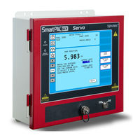
Wintriss SmartPAC PRO Servo User Manual (228 pages)
Press Automation Control
Brand:
Wintriss
| Category:
Controller
| Size: 11 MB
Table of Contents
Table of Contents
5
List of Tables
12
Chapter 1 - Introduction
19
Figure 1-1. Smartpac PRO Servo Front Panel
19
Smartpac PRO Servo Standard Features
20
Smartpac PRO Servo Operation
21
Smartpac PRO Servo Options
21
Smartpac PRO Servo Settings
21
Sensors Available for Dipropac
22
Programmable Cam Channels
23
Smartpac PRO Servo's Three Modes of Operation
23
Smartpac PRO Servo Specifications
24
Table 1-1. Specifications
24
Chapter 2 - Installation
27
Before You Start
28
Installation Guidelines
28
Figure 2-1. Installation Overview
30
Checking the Press
31
Terminating Cable Shields
31
Figure 2-2. Smartpac PRO Servo Mounting Dimensions
32
Mounting the Smartpac PRO Servo Control Enclosure
32
Figure 2-3. Smartpac PRO Servo Panel Mount Cutout Dimensions
33
Installing Smartpac PRO Servo as a Panel Mount
33
Figure 2-4. Smartpac PRO Servo Panel Mount Dimensions
34
Installing Smartpac PRO Servo with Remote HMI
34
Installing the MTS Linear Transducer
35
Mounting the Transducer
35
Figure 2-5. Real Time Smartpac (RTS) Board Mounting Dimensions
35
Figure 2-6. MTS Linear Transducer Dimensions
36
Wiring the Transducer
37
Figure 2-7. Smartpac PRO Servo Board - Procampac Board, Left, Outlined in Red
37
Figure 2-8. Procampac Linear Boards, Location of Components
38
Wiring the Transducer to DC Power
39
Figure 2-9. MTS Linear Transducer Pinout
39
Table 2-1. MTS Linear Transducer Wiring
39
Connecting Power Wiring - AC Powered Units
40
Figure 2-10. Wiring AC to Terminal Block, Inside Enclosure, Top Right
40
Connecting Power Wiring - 24 VDC Powered Units
41
Connecting Stop Circuits and Input Check Circuit
41
Figure 2-11. Location of Terminal Blocks TB1 to TB8
41
Making Wiring Connections
42
Setting the Input Check Voltage Switch
42
Table 2-2. Stop and Input Check Circuit Wiring Connections: TB4
42
Adding or Upgrading Dipropac or Procampac
43
Connecting to the Network
43
Figure 2-12. Input Check Voltage Switch (S101) in the Factory Default (60-250V) Position
43
Figure 2-13. Smartpac PRO Servo Board Dipropac Board, Right, Outlined in Red
44
Connecting Dipro Sensor Interface to Smartpac PRO Servo
45
Table 2-3. Dipro Sensor Interface (DSI) 2 to Smartpac PRO Servo Wiring, Sensors 1-8
46
Table 2-4. Dipro Sensor Interface (DSI) 2 to Smartpac PRO Servo Wiring, Sensors 9-16
47
Table 2-5. Dipro Sensor Interface (DSI) 2 to Smartpac PRO Servo Wiring, Sensors 17-24
48
Table 2-6. Dipro Sensor Interface (DSI) 2 to Smartpac PRO Servo Wiring, Sensors 25-32
48
Connecting Programmable Cam Channels
49
Figure 2-14. Procampac Output Assembly
50
Figure 2-15. Cam Outputs Board
51
Table 2-7. Procampac Linear to Cam Output Assembly TB301 Wiring, Cams 1-8
52
Figure 2-16. TB302 and TB 303 for Wiring Relays to Equipment
53
Table 2-8. Procampac Linear to Cam Output Assembly TB301 Wiring, Cams 9-15
53
Figure 2-17. Install Suppressors Across AC Loads
54
Figure 2-18. Installing a Diode Across a DC Load
54
Table 2-9. Connections to Relays
54
Wiring a Remote Reset Switch (Optional)
55
Wiring a Sensor-Disabled Output (Optional)
55
Wiring Setup Mode Circuit
55
Figure 2-19. Main Program Menu
56
Turning on Power to Smartpac PRO Servo
56
Figure 2-20. Main Program Menu
57
Verifying Installation of Dipropac and Procampac
57
Figure 2-21. Main Initialization Menu
58
Figure 2-22. Installed Options Screen
58
Check Stroke Limits
59
Check the Top-Stop Circuit
59
Check the Emergency-Stop Circuit
59
Check Cam Channels
59
Test Complete
59
Final Checkout
58
Set up a "Test" Tool
58
Table 2-10. Auxiliary Port (TB5) Wiring
60
Table 2-11. SFI Port and Module Port (TB6) Wiring
60
What Next
60
Wiring Tables for Smartpac PRO Servo Options
60
Table 2-12. Special Port and aux (TB7) Wiring
61
Table 2-13. WPC Port and Spare 1 Port (TB8) Wiring
61
Table 2-14. Stop and Input Check Circuit (TB4) Wiring
62
Chapter 3 - Displays and Operating Modes
63
Figure 3-1. Smartpac PRO Servo
63
Figure 3-2. Smartpac PRO Servo Operating Modes, Showing Main Menus
64
Smartpac PRO Operating Modes
64
Table 3-1. Initialization, Program and Run Modes: Entry and Exit Procedures
65
Initialization Mode
66
On-Screen Data Entry
66
On-Screen Numeric Keypad
66
Program Mode
66
Run Mode
66
Figure 3-3. Numeric Keypad
67
Figure 3-4. Smartpac PRO Servo On-Screen Keyboard
67
On-Screen Keyboard
67
Screen Captures
68
Table 3-2. Button Descriptions
68
The "ALT" Menu
68
Figure 3-5. Save to USB Disk
69
Figure 3-6. USB Disk Error Message
69
Chapter 4 - Smartpac PRO Servo Initialization Mode
71
Figure 4-1. Main Initialization Menu
71
Figure 4-2. Main Initialization Menu, Next Items
72
Angle Wheel Rotation (Clockwise - Counterclockwise)
73
Position Sensor
73
Position Sensor Mode
73
Resolver Motion Mode (Normal Motion - Link Motion)
73
Counter Increment Mode
74
Counter Setup Mode
74
Installed Options
75
Options Manager
75
Preferences
76
Select Language (Optional)
77
Table 4-1. Preferences
77
Press Name
78
SELECT CAM NAMES (Optional)
78
SET GLOBAL CAMS (Optional)
80
CUSTOM SENSOR NAMES (Optional)
82
Selecting Sensor Enable Mode
83
SENSOR ENABLE MODE (Optional)
83
Enabling Setup Mode
84
Linear Sensor
84
Table 4-2. Linear Sensor Setup Screen Field Definitions
86
Tool Information
87
Table 4-3. Tool Information Setup Screen: Abbreviations for Units
90
Table 4-4. Tool Information Setup Screen: Decimal Places and Formats
91
Security Access
92
Table 4-5. Security Access Settings
94
Setting Security Access
95
Changing Passwords
96
Backup/Restore
97
Backing up Tools to a USB Disk
98
Restoring Tools from a USB Disk
98
SETUP DATA COMMS (Optional)
98
E-Mail Function
99
Setup Network
99
Change Network Settings
100
Press Type
100
Setup E-Mail
100
Smartview Function
100
Diagnostics
101
Communications
102
Set Clock
102
Save to Usb Disk
103
Update Firmware
104
Chapter 5 - Program Mode
105
Entering and Exiting Program Mode
106
Tool Manager
106
Table 5-1. Instructions for Entering and Exiting Program Mode
106
Creating a New Tool
107
Copying an Existing Tool
108
Copying Tool Template to a New Tool
109
Loading a Tool
110
Changing Settings for a Loaded Tool
111
Deleting a Tool
112
Tool Program Menu
112
Tool Name
113
Counters
114
Setting Preset Values
115
Changing Count Values
116
Clearing the Total Hits Counter
117
Setting Batch Counter Output and Increment Modes
117
Setting Counter Increment Angle
118
Setting Parts Per Stroke or Strokes Per Part
119
Setting Batch Pre-Load Counts
120
DIE PROTECTION (Optional)
120
Understanding Sensor Terminology
121
Programming Sensor Settings
125
Programming Dipropac 32 Sensors
136
Cam Switch
142
Selecting a Cam Channel
144
Making an ON/OFF Setting
145
Setting Multiple ON/OFF Cycles
145
Table 5-2. Additional On/Off Settings, 8-Channel Procampac: Examples
146
Making a Timed Output Setting
148
Setting DSV on Channel Timing
149
Deleting Channel Settings
150
Viewing Global Cams
151
Viewing the Cam Summary
151
Tool Information
152
Ram Position
154
SENSOR ENABLE/DISABLE & STATUS (Optional)
156
Enabling or Disabling All Sensors
157
Turning a Sensor off or on
157
Viewing Sensor Status
157
Chapter 6 - Run Mode
159
Entering and Exiting Run Mode
160
Loading a Tool
161
Settings Locked, or Password Required
161
Table 6-1. Instructions for Entering and Exiting Run Mode
161
Displaying Multiple Faults
162
Opening the Ram Angle Window
162
Disable (Enable) Sensors
163
Counters
165
DIE PROTECTION (Optional)
167
Adjusting the Ready Signal for Green Sensors
168
Adjusting the Stroke Preset for Green Special Sensors
170
Viewing the Sensor Summary
170
Viewing Sensor Status
171
Adjusting Dipropac 32 Sensors
172
Cam Switch
175
Viewing Cam Timing
176
Viewing the Global Cam Summary
177
Viewing the Cam Summary
177
Tool Information
177
Ram Position
179
Error/Event Log
180
Load New Tool
181
Messaging
182
Sending E-Mail to Wintriss Technical Support
184
Chapter 7 - Fault Messages
185
Responding to Fault Messages
186
Batch # Counter Preset Reached
187
Counter Preset Reached Messages
187
Good Parts Counter Preset Reached
187
Linear Transducer Output Is Not Correct. Cable May be Disconnected. the Transducer Output Is Reading Incorrectly. Check that the Cable Is Connected and Has Power
187
Messages for Equipment Problems
187
Strokes Counter Preset Reached
187
E-Stop Errors
188
Inboard Ram Test Failure
188
Messages for Programming Problems
188
No Tool Number Has Been Loaded
188
Position Sensor Incorrect
188
Tool Number Table Checksum Error
188
Green Sensor Actuated Late
189
Green Sensor Missed
189
Messages for Sensor Faults
189
Fault Message for Yellow Sensors "This N/O Sensor Is Grounded
190
Green Constant Fault
190
Green Quick Check Sensor Actuated Outside Ready
190
Green Sensor Failure
190
Green Special Fault
190
Fault Message for Red Sensors "This N/C Sensor Is Open
191
Loss of Communication at Address X
191
Miscellaneous Fault Messages
191
One of the Sensor Auto Enable Counters Is Greater than 99
191
Table 7-1. Communication Errors: Smartpac PRO Servo Option Identified by Address Number
191
The Press Cycle was Interrupted before Upper or Lower Limits Were Reached
191
File Not Found
192
Troubleshooting Using the Error/Event Log
192
Appendix A - Installing the Balluff Linear Transducer
193
Mounting the Transducer
193
Wiring the Transducer
194
Glossary
197
Index
199
Advertisement
Advertisement
Related Products
Wintriss SmartPAC2
Wintriss SmartPAC PRO
Wintriss SmartPAC
Wintriss Shadow VI
Wintriss ShopFloorConnect SMI 2
Wintriss WPC 1000
Wintriss wpc 2000
Wintriss Categories
Controller
Industrial Equipment
Recording Equipment
Measuring Instruments
Indoor Furnishing
More Wintriss Manuals
Login
Sign In
OR
Sign in with Facebook
Sign in with Google
Upload manual
Upload from disk
Upload from URL