Sign In
Upload
Manuals
Brands
Wintriss Manuals
Controller
wpc 2000
Wintriss wpc 2000 Manuals
Manuals and User Guides for Wintriss wpc 2000. We have
2
Wintriss wpc 2000 manuals available for free PDF download: User Manual
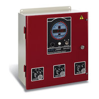
Wintriss wpc 2000 User Manual (250 pages)
clutch/brake control
Brand:
Wintriss
| Category:
Controller
| Size: 2 MB
Table of Contents
Table of Contents
6
Chapter 1 Introduction
18
WPC 2000 Components
18
Resolver
18
Control Enclosure
18
Figure 1-1. WPC 2000 Control Enclosure and Display
19
Operator Station
20
Figure 1-2. Operator Station Components (Side-Mounted Run/Inch Palm Buttons)
20
Other Components
21
Dual-Monitored Safety Valve (DSV)
21
Shadow Light Curtain
21
System Air Pressure Switch
21
WPC 2000 Display
21
Standard Features
22
Optional Features
23
Specifications
25
Table 1-1. WPC 2000 Specifications
25
Chapter 2. Installation
28
Installation Guidelines
30
Figure 2-1. WPC 2000 Wiring Overview
31
Connecting Wires to Terminal Block Connectors
32
Figure 2-2. Correct Way to Attach Wires to Terminal Block Connectors
32
Terminating Cable Shields
32
Mounting the Control Enclosure
33
Wiring the Control Enclosure
33
Figure 2-3. Cable Shield Termination
33
Figure 2-4. WPC 2000 Enclosure: Mounting Dimensions
34
Slide Adjust Considerations
34
Connecting AC Wiring
35
Figure 2-5. AC Input Wiring Connections
35
Installing a Dual Safety Valve
36
Installing Air Pressure Switches
38
Installing a Clutch Air Pressure Switch
38
Installing a Counterbalance Air Pressure Switch
39
Installing Operator Station(S)
39
Wiring a Pre-Wired Operator Station
40
Checking Pre-Wired Operator Station Wiring
40
Figure 2-6. Pre-Wired Operator Stations Showing Mute Lamp Connections
40
Figure 2-7. Wiring Steps to Modify Operator Station for WPC 2000
41
Figure 2-8. Pre-Wired Operator Station with Side Run Buttons: Mounting Dimensions
42
Figure 2-9. Pre-Wired Operator Station with Top Run Buttons: Mounting Dimensions
42
Making Wiring Connections
42
Wiring an Unwired Operator Station
43
Figure 2-10. Unwired Operator Station: Mounting Dimensions
43
Wiring a User-Built Operator Station
44
Installing Multiple Operator Stations
44
Installing a Light Curtain
45
Installing Shadow Light Curtains
46
Setting Jumpers for Shadow VII and Shadow 8 Light Curtains
46
Installing Non-Shadow Light Curtains
46
Table 2-1. Shadow VII and Shadow 8 Light Curtain Jumper Settings
46
Installing the Resolver
47
Mounting the Resolver
48
Figure 2-11. Resolver: Mounting Dimensions
48
Wiring the Resolver
49
Important Components
50
Checking the Resolver's Direction of Rotation
52
Replacing the Resolver
52
Installing the Overrun Limit Switch
52
Planning Your Overrun Sensor Installation
53
Mounting the Overrun Sensor Switch
53
Wiring the Overrun Sensor Switch
54
Table 2-2. Overrun Sensor Switch Wiring Connections
54
Wiring WPC 2000 User Inputs
55
Table 2-3. WPC 2000 User Inputs: Stop Types, Fault Codes, and Wiring Connections
56
Wiring the Lockout Relay
57
Wiring Auxiliary Outputs
57
Table 2-4. Lockout Relay Wiring Connections (Dsv/Lockout Relay Board)
57
Auxiliary Output 1
58
Table 2-5. Auxiliary Output Wiring Connections and Change Conditions
58
Table 2-6. Option Switch 8 Settings for Auxiliary Output 1 State Change
58
Auxiliary Output 2
59
Connecting Multiple Controls to the Resolver
59
Connecting Other Wintriss Products to WPC 2000
60
Wiring Micro-Inch
60
Table 2-7. Micro-Inch Wiring Connections
61
Figure 2-16. WPC 2000 Display Board: Location of Important Components
61
Disabling Top-Stop in Inch
62
Wiring a Remote Reset Switch
62
Installing 4-Channel Programmable Cam
62
Table 2-8. Remote Reset Switch Wiring Connections
62
Mounting and Wiring the Cam Output Assembly
63
Figure 2-17. Cam Output Enclosure: Mounting Dimensions
64
Making Wiring Connections to Cam Relays
65
Table 2-9. WPC 2000 Main Processor Board (TB109) to Cam Output Assembly (TB1)
65
Wiring Connections
65
Figure 2-19. Connectors TB2 through TB5 on Cam Output Board
66
Enabling Cam Adjustments
67
Setting Switch 1 on S102 on the Main Processor Board
68
Setting Switch S701 on the Display Board
68
Wiring a Remote Switch
68
Wiring Zero Cam Output to Autoset
69
Wiring a Foot Switch
69
Table 2-10. Zero Cam Output Wiring Connections
69
Table 2-11. Foot Switch Wiring Connections
69
Installing a One-Hand Control
70
Mounting a One-Hand Control
71
Wiring a One-Hand Control to WPC 2000
72
Table 2-12. One-Hand Control Wiring Connections
73
Figure 2-25. Wiring Connections in One-Hand Control Switch (Switch Cover, Bottom View)
73
Mounting and Wiring the Bar Control Enclosure
74
Table 2-13. Bar Control Wiring Connections
74
Wiring Automatic Single-Stroke
75
Wiring Automatic Continuous On-Demand
75
Table 2-14. Automatic Single-Stroke Wiring Connections
75
Installing Revised Firmware in WPC 2000
76
Installing WPC 2000 Without Enclosure
78
Installing the WPC 2000 Mounting Plate
78
Installing the Panel-Mount Display
79
Mounting the Display
79
Figure 2-28. WPC 2000 Panel Mount Display: Mounting and Cutout Dimensions
80
Board
81
Installing Selector Switches and Final Assembly
81
Table 2-15. Display Cable Wiring Connections, Display Board to Main Processor Board
81
Installing Display Board Kit with Selector Switches
82
Table 2-16. Selector Switch Wiring Connections
82
Figure 2-30. WPC 2000 Display Board Kit: Mounting and Cutout Dimensions
83
Figure 2-31. Reset/Select Button Wiring Connections
84
Installation Verification
85
Checking Safeguarding Devices
86
Checking Dual Safety Valve (DSV) Wiring
87
Checking for Faults
88
Checking the Emergency-Stop Circuit
88
Installation Verification Complete
88
Wiring Tables
88
Table 2-17. WPC 2000 Main Processor Board, TB101-TB104: Wiring Connections
89
Table 2-18. Power Supply (TB105) Wiring
90
Table 2-19. Aux. E-Stop Relay Board Wiring
90
Table 2-20. Dsv/Lockout Relay Board Wiring
90
Table 2-21. Resolver (TB 106) Wiring
90
Table 2-22. Cam Outputs (TB 109) Wiring
90
Table 2-23. Display Board Wiring
90
Table 2-24. AC Power Wiring
90
Chapter 3. Initialization, Setup, and Checkout
92
Viewing and Setting Press Parameters
92
Table 3-1. WPC 2000 Display: Default Parameters (Press Running)
93
Figure 3-1. WPC 2000 Display Showing Indicator Segments
93
Initializing the System
94
Re-Zeroing the Resolver
95
Initializing Only the Start-Time Limit
96
Viewing the Start-Time Limit
96
Viewing the Last Start Time
96
Installing the Overrun Sensor Magnet
97
Setting the Top-Stop "On" Angle
97
Table 3-2. Overrun Sensor Magnet Location and Option Switch Settings
99
Mounting the Overrun Sensor Magnet
100
Figure 3-6. WPC 2000 Display Showing Overrun Sensor "On" Angle
101
Adjusting the Top-Stop Angle
102
Setting the Auto Carry-Up Angle
104
Running Brake Monitor Tests and Making Settings
105
Determining the Stopping Time of Your Press
105
Calculating the Stop-Time Limit
106
Setting the Stop-Time Limit
107
Determining the 90° Stop Time
108
Performing the 90° Stop Test (Continuous Mode)
108
Performing the 90° Stop Test (Single-Stroke Mode)
109
Calculating the Safety Distance
110
ANSI and OSHA Safety Distance Formulas
111
ANSI Safety Distance Formula
112
Table 3-3. Shadow Light Curtain Response Time and Object Sensitivity
112
OSHA Safety Distance Formula
114
Adding to Safety Distance for Blanking Windows
115
Setting Micro-Inch
116
Setting Press Option Switches
117
Making Settings on Switch Block S101
117
Switches 1 and 2 - Top-Stop "On" Angle Range
117
Switch 3 - One-Hand Control and Foot Switch Settings
118
Table 3-4. Switches 1 and 2 Settings (S101): Top-Stop "On" Angle Range
118
Table 3-5. Switch 3 Settings (S101): Enabling Light Curtain Break Mode
118
Switch 4 - Enabling Auto Compensated Top Stop (ACTS)
119
Table 3-6. Switch 3 Settings (S101): Enabling Foot Control
119
Table 3-7. Switch 4 Settings (S101): Enabling ACTS
119
Settings
120
Switch 5 - Prior Act Time for Automatic Stroke Modes
120
Switch 6 - Enabling Dual Light Curtains
120
Table 3-8. Switch 5 Settings (S101): Prior Act Times for Automatic Modes
120
Table 3-9. Switch 6 Settings (S101): Enabling Cam Adjustments
120
Switch 8 - Top-Stop Mode for F and H Errors and Auxiliary Output 1 Response to Interrupted Stroke
121
Table 3-10. Switch 7 Settings (S101): Disabling Access to Stop-Time Limit and Auto
121
Table 3-11. Switch 8 Settings (S101): Top-Stop Mode for F and H Errors
121
Making Settings on Switch Block S102
122
Table 3-12. Switch 8 Settings (S101): Auxiliary Output 1 Response to Interrupted Stroke
122
Switch 1 - Set Cams Function
123
Switch 2 - Auxiliary E-Stop Relay Muting Function
123
Table 3-13. Switch 1 Settings (S102): Enabling Set Cams Function
123
Table 3-14. Switch 2 Settings (S102): Enabling E-Stop Muting Function
123
Stations
124
Switch 6 - Selecting Concurrent Time for more than Two Operator
124
Setting Programmable Cams
124
Table 3-15. Switch 6 Settings (S102): Selecting Concurrent Time for Multiple Op. Stations
124
Figure 3-12. Cam Channel Settings Display: Cam 1 on Angle (270°) Shown
125
Final Checkout
126
Figure 3-14. WPC 2000 LED Indicator Map (Center- or Right-Mounted Board)
128
Figure 3-15. WPC 2000 LED Indicator Map (Left-Mounted Board)
129
Checking the Emergency-Stop Circuit
130
Checking for Faults When the Press Is Running
131
Checking the Top-Stop Circuit
131
Power Supply Test
132
Shadow Light Curtain Test
132
System Static Test
134
Single-Stroke Mode Test with Light Curtain(S)
136
Single Stroke Mode Test Without Light Curtain(S)
138
Anti-Tiedown Test
139
Anti-Repeat Test
140
Continuous Mode Test with Light Curtain(S)
141
Continuous Mode Test Without Light Curtain(S)
143
Foot Switch Test
145
One-Hand Control Test
147
Bar Mode Control Test
148
Checking Operation of the User Inputs
149
Chapter 4. Operation
150
Responding to an Interrupted Stroke
152
Responding to a Brake Warning
152
Stopping Angle
153
Displaying and Clearing the Stroke Counter
154
Viewing the Counter Value
154
Resetting the Counter Value to Zero
155
Setting and Maintaining the Counter Preset Value
155
Setting the Counter Preset
155
Disabling the Counter Preset
156
Forcing the Counter Preset Value to 999999
157
Operating the Press in Inch Mode
157
Top-Stop in Inch
158
Top-Stop Bypass (Top-Stop in Inch Disabled)
158
Micro-Inch
159
Dead Motor Inch
159
Operating the Press in Single-Stroke Mode
160
Single-Stroke, Two-Hand Operation
160
Single-Stroke, One-Hand Operation
161
Single-Stroke, One-Hand Control Operation
162
Single-Stroke, Foot Operation
164
Operating the Press in Automatic Single-Stroke Mode
165
Operating the Press in Continuous Mode
166
Continuous, Two-Hand Operation
166
Continuous, Foot Operation
167
Operating the Press in Automatic Continuous On-Demand Mode
168
Operating the Press in Bar Mode
168
Multiple Operator Stations
169
Chapter 5. Troubleshooting
170
Responding to WPC 2000 Faults
171
Table 5-1. Fault Codes: Significance of Initial Letter
171
Lockout Message
172
Brake Monitor Faults
172
Brake Warning LED
172
Stop Time Exceeded
173
E, F, and H Faults
174
Resolver Faults
175
Operational Faults
176
Inter-Processor Failures
180
Input Buffer Test Failures
181
Component Failures
181
Customized Status Codes
182
Table 5-2. Fault Codes for User Inputs
182
Light Curtain Faults
183
Emergency-Stop Circuit Driver Failure
184
Top-Stop Circuit Driver Failure
184
Shadow Light Curtain Input Faults
185
DSV Interface and Lockout Relay Failures
185
Loss of Rotation
186
Internal Timing Input Failures
187
Top-Stop and Overrun Setting Faults
187
Overrun Limit Switch Fault
187
Overrun Limit Switch Test Angle Fault
188
Overrun Limit Switch Setting Fault
188
Internal Memory Failures
189
Resetting Ross DM2 DSV Faults
189
Figure 5-4. Ross DM2 DSV Showing Reset Button
190
Appendix A. Extracts from OSHA Regulations and ANSI
192
Extracts from OSHA Regulation 1910.217
192
Appendix B. Specifications for User-Built Operator Stations
210
Run Button Installation
210
Table B-1. Operator Station Requirements
210
Switch Requirements
211
Table B-2. Specifications for Operator Station Switches
211
Appendix C. Option 1 User Inputs
212
Table C-1. Option 1 User Inputs: Input Type and Stop Type
213
Installing the Option 1 Board
214
Figure C-1. Option 1 Board Installed on WPC 2000 Main Processor Board
215
Wiring Option 1 User Inputs
216
Table C-2. WPC 2000 Option 1 Board: Wiring Connections, TB601
217
Figure C-3. WPC 2000 Option 1 Board: LED Map
218
Troubleshooting
219
Glossary
220
Index
226
Wintriss Manuals
230
Advertisement
Wintriss wpc 2000 User Manual (96 pages)
Brand:
Wintriss
| Category:
Industrial Equipment
| Size: 2 MB
Table of Contents
Table of Contents
7
Chapter 1 - Introduction
17
Expanded User Inputs
17
Hydraulic Overload Control
18
Flywheel Brake Control
19
Other Standard Features
20
Motor Current Readout
20
Top-Stop Output Relay for Auxiliary Devices
20
Dual Safety Valve (DSV) Reset
20
Lube Control
20
Lube 1
20
Monitor 1 and 2
21
Speed Control
21
Specifications
22
Table 1-1. Option 2 Specifications
22
Chapter 2 - Installation
23
Installing the Option 2 Board
23
Figure 2-1. Option 2 Board Installed on WPC 2000 Main Processor Board
24
Table 2-1. Option 2 Board: CAN Bus Wiring Connections (TB605)
25
Replacing Option 2 Firmware
26
Wiring User Inputs
28
Figure 2-2. Option 2 Board: Location of Important Components
29
Table 2-2. Option 2 Board: User Input Wiring Connections (TB601)
30
Wiring Hydraulic Overload Inputs and Outputs
31
Wiring Flywheel Brake Inputs and Outputs
32
Wiring Top Stop Outputs
32
Wiring Lube Control Inputs and Outputs
32
Table 2-3. Option 2 Board: Lube Control and Other Input Connections (TB603)
33
Table 2-4. Option 2 Board: Lube Control and Other Output Connections (TB606)
33
Wiring Analog Speed Control Inputs and Outputs
34
Installing and Wiring a Motor Current Transducer
35
Installing the Transducer
35
Wiring the Transducer
35
Table 2-5. Option 2 Board: Speed Control Connections (TB604)
36
Figure 2-3. Option 2 Board: LED Map
37
Chapter 3 - Setting Option 2 Initialization Parameters
39
Accessing the Smartpac PRO Main Initialization Menu
39
Making and Viewing User Input Settings
39
Setting User Input Stop Type and Name
39
Figure 3-1. Smartpac PRO Main Initialization Menu
39
Figure 3-2. WPC Initialization Menu
40
Figure 3-3. Change User Interlocks Screen
40
Figure 3-4. Press Control User Interlock Menu for Group 2 User Inputs
41
Viewing the Status of User Inputs
42
Figure 3-5. WPC Initialization Menu
42
Figure 3-6. Display WPC Input Status Screen
42
Accessing the Lube/Speed/Flywheel Brake Init. Menu
43
Figure 3-7. WPC Interlock Group 2 Input Status Screen
43
Figure 3-8. Smartpac PRO Main Initialization Menu
43
Making Flywheel Brake and Related Settings
44
Figure 3-9. Lube/Speed/Flywheel Brake Initialization Menu
44
Figure 3-10. Flywheel Brake Setup Screen
44
Table 3-1. Flywheel Brake Setup Screen Settings
45
Setting Flywheel Brake Initialization Parameters
46
Enabling the "Dead Motor Inch" Feature
46
Setting Top Stop Output Mode
47
Setting Maximum Transducer and Motor Current
47
Making Lube Control Settings
48
Figure 3-11. Lube/Speed/Flywheel Brake Initialization Menu
48
Figure 3-12. View or Change Lubrication Setup Menu
49
Figure 3-13. Press Lubrication Setup Screen
49
Table 3-2. Press Lubrication Setup Screen Settings
50
Setting Lube 1 Initialization Parameters
52
Setting Monitor 1 and 2 Initialization Parameters
54
Figure 3-14. Press Lubrication Setup Screen, INTERVAL
55
Figure 3-15. Press Lubrication Setup Screen, ACTUATIONS
55
Figure 3-16. Press Lubrication Setup Screen with Monitor Switch Count Interval
55
Figure 3-17. Press Lubrication Setup Screen with Monitor Switch Count Actuations
56
Table 3-3. Actuations Check Frequency
57
Making Speed Control Settings
58
Figure 3-18. Lube/Speed/Flywheel Brake Initialization Menu
58
Figure 3-19. Press Speed Setup Screen
59
Table 3-4. Press Speed Setup Screen Settings
59
Resetting a Dual Safety Valve (DSV)
60
Figure 3-20. Dual Safety Valve Reset Function on WPC Initialization Menu
60
Viewing the Status of Option 2 Inputs and Outputs
61
Figure 3-21. Display WPC Input Status Screen
61
Chapter 4 - Setting Press Speeds in Program Mode
63
Table 4-1. Press Control Parameters Screen Settings
65
Chapter 5 - Using Option 2 in Run Mode
67
Calibrating Speed Control Settings
67
Adjusting Press Speed
71
Monitoring Motor Current
72
Table 5-1. Press Control Run Screen Settings
72
Operating the Press in "Dead Motor Inch
74
Chapter 6 - Troubleshooting
75
General Faults
75
User Input Faults
78
Table 6-1. WPC 2000 Option 2 User Input Fault Codes
78
Hydraulic Overload Faults
79
Flywheel Brake Faults
82
DSV Faults
82
Lube Faults
83
Speed Control Faults
85
Appendix A - Option 2 User Input Setup Sheet
87
Appendix B - Lube Control Setup Guide
89
Index
91
Advertisement
Related Products
Wintriss WPC 1000
Wintriss SmartPAC
Wintriss SmartPAC PRO
Wintriss SmartPAC PRO Servo
Wintriss SmartPAC2
Wintriss Categories
Controller
Industrial Equipment
Recording Equipment
Measuring Instruments
Network Card
More Wintriss Manuals
Login
Sign In
OR
Sign in with Facebook
Sign in with Google
Upload manual
Upload from disk
Upload from URL