Sign In
Upload
Manuals
Brands
Wintriss Manuals
Controller
WPC 1000
Wintriss WPC 1000 Manuals
Manuals and User Guides for Wintriss WPC 1000. We have
1
Wintriss WPC 1000 manual available for free PDF download: User Manual
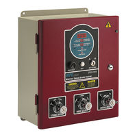
Wintriss WPC 1000 User Manual (235 pages)
Clutch Brake Control
Brand:
Wintriss
| Category:
Controller
| Size: 2 MB
Table of Contents
Table of Contents
6
Chapter 1. Introduction
18
WPC 1000 Components
18
Resolver
18
Control Enclosure
18
Figure 1-1. WPC 1000 Control Panels
19
Operator Station
20
Figure 1-2. Operator Station Components (Side-Mounted Run/Inch Palm Buttons)
20
Other Components
21
Dual-Monitored Safety Valve (DSV)
21
Clutch Air Pressure Switch
21
Shadow Light Curtain
21
Displays
21
Standard Display
21
Figure 1-3. WPC 1000 Displays
22
Optional Counter and Crank-Angle Clock Display
23
Standard Features
23
Optional Features
24
Specifications
26
Table 1-1. WPC 1000 Specifications
26
Chapter 2. Installation
28
Installation Guidelines
30
Figure 2-1. WPC 1000 Wiring Overview
31
Connecting Wires to Terminal Block Connectors
32
Figure 2-2. Correct Way to Attach Wires to Terminal Block Connectors
32
Terminating Cable Shields
32
Mounting the Control Enclosure
33
Wiring the Control Enclosure
33
Figure 2-3. Cable Shield Termination
33
Figure 2-4. WPC 1000 Mounting Dimensions
34
Slide Adjust Considerations
34
Connecting AC Wiring
35
Installing a Dual Safety Valve
36
Figure 2-5. AC Input Wiring Connections
36
Installing Clutch and Counterbalance Air Pressure Switches
38
Installing Operator Station(S)
39
Wiring a Pre-Wired Operator Station
40
Checking Pre-Wired Operator Station Wiring
40
Figure 2-6. Pre-Wired Operator Stations Showing Mute Lamp Connections
40
Making Wiring Connections
41
Figure 2-7. Wiring Steps to Modify Operator Station for WPC 1000
41
Figure 2-8. Pre-Wired Operator Station with Side Run Buttons: Mounting Dimensions
42
Figure 2-9. Pre-Wired Operator Station with Top Run Buttons: Mounting Dimensions
42
Wiring an Unwired Operator Station
43
Figure 2-10. Unwired Operator Station: Mounting Dimensions
43
Wiring a User-Built Operator Station
44
Installing Multiple Operator Stations
44
Installing a Light Curtain
45
Installing Shadow Light Curtains
45
Setting Jumpers for Shadow VII and Shadow 8 Light Curtains
46
Installing Non-Shadow Light Curtains
46
Table 2-1. Shadow VII and Shadow 8 Light Curtain Jumper Settings
46
Installing the Resolver
49
Mounting the Resolver
50
Figure 2-13. Resolver: Mounting Dimensions
50
Wiring the Resolver
51
Checking the Resolver's Direction of Rotation
52
Replacing the Resolver
52
Installing the Overrun Limit Switch
52
Planning Your Overrun Sensor Installation
53
Mounting the Overrun Sensor Switch
53
Figure 2-14. Overrun Sensor Magnet Placement: Dwell as a Function of Shaft Diameter
53
Wiring the Overrun Sensor Switch
54
Figure 2-15. Overrun Sensor Magnetic Switch: Installation Example
54
Table 2-2. Overrun Sensor Switch Wiring Connections
54
Wiring WPC 1000 User Inputs
55
Wiring the Lockout Relay
56
Table 2-3. WPC 1000 User Inputs: Stop Types, Fault Codes, and Wiring Connections
56
Wiring the Auxiliary Output
57
Table 2-4. Lockout Relay Wiring Connections (Dsv/Lockout Relay Board)
57
Table 2-5. Auxiliary Output 1 Wiring Connection and Change Conditions
57
Connecting Multiple Controls to the Resolver
58
Table 2-6. Option Switch 8 Settings for Auxiliary Output 1 State Changes
58
Connecting Other Wintriss Products to WPC 1000
59
Wiring Micro-Inch
59
Disabling Top-Stop in Inch
60
Figure 2-16. WPC 1000 Display Board: Location of Important Components
60
Table 2-7. Micro-Inch Wiring Connections
60
Wiring a Remote Reset Switch
61
Installing 2-Channel Programmable Cam
61
Mounting and Wiring the Cam Output Assembly
61
Table 2-8. Remote Reset Switch Wiring Connections
61
Figure 2-17. Cam Output Enclosure: Mounting Dimensions
62
Figure 2-18. Cam Output Board: Mounting Dimensions
63
Table 2-9. WPC 1000 Control Board to Cam Output Assembly (TB1) Wiring Connections
63
Making Wiring Connections to Cam Relays
64
Figure 2-19. Connectors TB2 and TB3 on Cam Output Board
64
Figure 2-20. Installing a Suppressor Across an AC Load
65
Wiring Zero Cam Output to Autoset
66
Wiring Foot Switch
66
Figure 2-21. Installing a Diode Across a DC Load
66
Table 2-10. Zero Cam Output Wiring Connections
66
Installing One-Hand Control
67
Table 2-11. Foot Switch Wiring Connections
67
Mounting the One-Hand Control
68
Figure 2-22. One-Hand Control Switch: Mounting Dimensions
69
Figure 2-23. One-Hand Control Switch Base: Mounting Dimensions
70
Wiring One-Hand Control to WPC 1000
70
Figure 2-24. Wiring Connections in One-Hand Control Switch
71
Table 2-12. One-Hand Control Wiring Connections
71
Mounting and Wiring the Bar Control Enclosure
72
Figure 2-25. Bar Control Enclosure: Mounting Dimensions
72
Table 2-13. Bar Control Wiring Connections
72
Installing Revised Firmware in WPC 1000
73
Installing WPC 1000 Without Enclosure
75
Installing the WPC 1000 Mounting Plate
75
Installing the Panel-Mount Display
76
Mounting the Display
76
Connecting the Panel-Mount Display to the WPC 1000 Control Board
77
Installing Selector Switches and Final Assembly
78
Table 2-14. Selector Switch Wiring Connections
78
Installing Display Board Kit with Selector Switches
79
Figure 2-29. WPC 1000 Display Board Kit: Mounting and Cutout Dimensions
80
Table 2-15. Reset Button, Settings Key Switch, and Mute Lamp Wiring Connections
81
Figure 2-30. Reset/Select Button Wiring Connections
81
Installing the Display Cable
82
Installing the Multicolored Ribbon Cable
82
Figure 2-32. Display Cable (Multicolored) with Gray Stripes Indicating Flat Area
83
Figure 2-33. Display Cable Jacket with Multicolored Ribbon Cable Exposed
84
Figure 2-35. Connector Top with Multicolored Ribbon Cable Conductors
85
Figure 2-37. Connector Halves Brought Together (Multicolored Conductors)
86
Installing the Shielded Gray Ribbon Cable
87
Figure 2-39. Gray Ribbon Cable with Connector and Insulated Shield
88
Figure 2-40. Display Cable Jacket with Gray Ribbon Cable and Shield Exposed
89
Figure 2-41. Connector Top with Gray Ribbon Cable Conductors and Shield
90
Figure 2-43. Connector Halves Brought Together (Gray Conductors)
91
Installation Verification
92
Checking Safeguarding Devices
93
Checking Dual Safety Valve (DSV) Wiring
94
Checking for Error Messages
95
Checking the Emergency-Stop Circuit
95
Installation Verification Complete
95
Wiring Tables
96
Table 2-16. WPC 1000 Control Board: TB101 and TB102 Wiring Connections
96
Table 2-17. WPC 1000 Control Board: Resolver (TB103) Wiring Connections
97
Table 2-18. WPC 1000 Control Board: Dsv/Lockout Relay Board Wiring Connections
97
Table 2-19. WPC 1000 Control Board: Power (J103) Wiring Connections
97
Table 2-20. WPC 1000 Display Board: Wiring Connections
98
Chapter 3. Initialization, Setup, and Checkout
100
Viewing and Setting Press Parameters
100
Table 3-1. WPC 1000 Standard Display Default Parameters (Press Running)
101
Figure 3-1. WPC 1000 Displays Showing Indicator Segments
101
Initializing the System
102
Table 3-2. WPC 1000 Optional Counter Display Default Parameters (Press Running)
102
Re-Zeroing the Resolver
103
Initializing Only the Start-Time Limit
104
Viewing the Start-Time Limit
105
Viewing the Last Start Time
105
Installing the Overrun Sensor Magnet
106
Setting the Top-Stop "On" Angle
106
Table 3-3. Overrun Sensor Magnet Location and Option Switch Settings
108
Figure 3-5. Setting Overrun Timing: Example
109
Mounting the Overrun Sensor Magnet
110
Adjusting the Top-Stop Angle
111
Setting the Auto Carry-Up Angle
113
Running Brake Monitor Tests and Making Settings
114
Determining the Stopping Time of Your Press
114
Calculating the Stop-Time Limit
115
Setting the Stop-Time Limit
116
Determining the 90° Stop Time
117
Performing the 90° Stop Test (Continuous Mode)
117
Performing the 90° Stop Test (Single-Stroke Mode)
118
Calculating the Safety Distance
119
ANSI and OSHA Safety Distance Formulas
120
ANSI Safety Distance Formula
121
Table 3-4. Shadow Light Curtain Response Time and Object Sensitivity
121
OSHA Safety Distance Formula
123
Adding to Safety Distance for Blanking Windows
124
Setting Micro-Inch
125
Setting Press Option Switches
126
Switches 1 and 2 - Top-Stop "On" Angle Range
126
Table 3-5. Switches 1 and 2 Settings: Top-Stop "On" Angle Range
126
Switch 3 - One-Hand Control and Foot Switch Settings
127
Enabling Light Curtain Break Mode in a One-Hand Control
127
Enabling Foot Control in a Foot Switch
127
Table 3-6. Switch 3 Settings: Enabling Light Curtain Break Mode
127
Switch 4 - Enabling Auto Compensated Top Stop (ACTS)
128
Table 3-7. Switch 3 Settings: Enabling Foot Control
128
Table 3-8. Switch 4 Settings: Enabling ACTS
128
Switch 5 - Selecting Concurrent Time for Multiple Op. Stations
129
Switch 6 - Enabling Access to Cam Settings
129
Table 3-9. Switch 5 Settings: Selecting Concurrent Time for Multiple Operator Stations
129
Settings
130
Switch 8 - Top-Stop Mode for F and H Errors and Auxiliary Output 1
130
Response to Interrupted Stroke
130
Selecting Top-Stop Mode for F and H Errors
130
Table 3-10. Switch 6 Settings: Enabling Cam Adjustments
130
Table 3-11. Switch 7 Settings: Disabling Access to Stop-Time Limit and Auto Carry-Up Angle
130
Auxiliary Output 1 Response to Interrupted Stroke
131
Table 3-12. Switch 8 Settings: Top-Stop Mode for F and H Errors
131
Table 3-13. Switch 8 Setting: Auxiliary Output 1 Response to Interrupted Stroke
131
Setting Programmable Cams
132
Figure 3-13. WPC 1000 Displays Showing Cam Channel 1 off Setting (Cam 1 on = 180°)
133
Final Checkout
134
Checking the Emergency-Stop Circuit
135
Checking the Top-Stop Circuit
136
Checking for Faults When the Press Is Running
136
Power Supply Test
137
Shadow Light Curtain Test
137
System Static Test
139
Single-Stroke Mode Test with Light Curtain(S)
141
Single Stroke Mode Test Without Light Curtain(S)
143
Anti-Tiedown Test
144
Anti-Repeat Test
145
Continuous Mode Test with Light Curtain(S)
146
Continuous Mode Test Without Light Curtain(S)
148
Foot Switch Test
149
One-Hand Control Test
151
Bar Mode Control Test
152
Checking Operation of the User Inputs
153
Chapter 4. Operation
154
Responding to an Interrupted Stroke
156
Responding to a Brake Warning
156
Displaying and Clearing the Stroke Counter
157
Viewing the Counter Value
157
Resetting the Counter Value to Zero
158
Setting and Maintaining the Counter Preset Value
158
Setting the Counter Preset
158
Disabling the Counter Preset
159
Forcing the Counter Preset Value to 999999
160
Operating the Press in Inch Mode
160
Top-Stop in Inch
161
Top-Stop Bypass (Top-Stop in Inch Disabled)
161
Micro-Inch
162
Dead Motor Inch
162
Operating the Press in Single-Stroke Mode
163
Single-Stroke, Two-Hand Operation
163
Single-Stroke, One-Hand Operation
164
Single-Stroke, One-Hand Control Operation
165
Single-Stroke, Foot Operation
167
Operating the Press in Continuous Mode
168
Continuous, Two-Hand Operation
168
Continuous, Foot Operation
169
Operating the Press in Bar Mode
170
Multiple Operator Stations
171
Chapter 5. Troubleshooting
172
Responding to WPC 1000 Faults
173
Table 5-1. Fault Codes: Significance of Initial Letter
173
Lockout Message
174
Brake Monitor Faults
174
Brake Warning LED
174
Stop Time Exceeded
175
E, F, and H Faults
176
Resolver Faults
176
Operational Faults
177
Inter-Processor Failures
181
Input Buffer Test Failures
181
Component Failures
182
Customized Status Codes
182
Light Curtain Faults
183
Table 5-2. Fault Codes for User Inputs
183
Emergency-Stop Circuit Driver Failure
184
Top-Stop Circuit Driver Failure
184
DSV Interface and Lockout Relay Failures
185
Loss of Rotation
186
Internal Timing Input Failures
186
Top-Stop and Overrun Setting Faults
187
Overrun Limit Switch Fault
187
Overrun Limit Switch Test Angle Fault
188
Overrun Limit Switch Setting Fault
188
Internal Memory Failures
188
Resetting Ross DM2 DSV Faults
189
Appendix A. Extracts from OSHA Regulations and ANSI
190
Standards
194
Controls
194
Appendix B. Specifications for User-Built Operator Stations
208
Run Button Installation
208
Table B-1. Operator Station Requirements
208
Switch Requirements
209
Table B-2. Specifications for Operator Station Switches
209
Appendix C. Old Control Board
210
Table C-1. Differences between New and Old Control Boards
211
Glossary
212
Index
218
Wintriss Manuals
222
Advertisement
Advertisement
Related Products
Wintriss wpc 2000
Wintriss SmartPAC
Wintriss SmartPAC PRO
Wintriss SmartPAC PRO Servo
Wintriss SmartPAC2
Wintriss Categories
Controller
Industrial Equipment
Recording Equipment
Measuring Instruments
Security Sensors
More Wintriss Manuals
Login
Sign In
OR
Sign in with Facebook
Sign in with Google
Upload manual
Upload from disk
Upload from URL