Sign In
Upload
Manuals
Brands
Veeder-Root Manuals
Water Pump
VTEK-3
Veeder-Root VTEK-3 Controller Board Manuals
Manuals and User Guides for Veeder-Root VTEK-3 Controller Board. We have
1
Veeder-Root VTEK-3 Controller Board manual available for free PDF download: Installation, Setup And Troubleshooting Manual
Veeder-Root VTEK-3 Installation, Setup And Troubleshooting Manual (58 pages)
Controller Board
Brand:
Veeder-Root
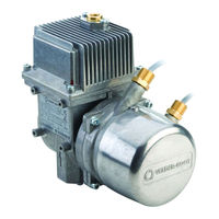
| Category:
Water Pump
| Size: 10 MB
Table of Contents
Table of Contents
3
Figure 1. Vaportek System Basic Components
5
Introduction
6
Contractor Certification Requirements
6
Figure 2. Auxiliary Vaportek System Components
6
Related Manuals
7
Safety Precautions
8
Safety Warnings
9
Vaportek Configurations
9
Vaportek Pump Certifications & Markings
10
Safety Certification
10
Hazardous Area Installation Instructions
10
Equipment Marking
10
Material Compatibility with Constituents of the Potentially Explosive Atmosphere
11
TUV Certification
11
Vaportek Kits
11
Vaportek Pump, ATEX/IECEX/ITRI Kit - P/N 900612-001
11
Vaportek Pump, ATEX/IECEX Kit - P/N 900882-001 (Salzkotten)
12
Vaportek Pump, PCEC Kit - P/N 900869-001 (China PCEC Version)
12
Vaportek-3 Controller Board Kit - P/N 900895-001
13
VTEK-3 Pulse Interface Adapter Kit - P/N 900905-001
15
Vaportek High Voltage Relay Kit - P/N 900664-001
15
Vaportek Valve Adapter Interface Kit - P/N 900XXX-001
16
Vaportek Pump Characteristics
16
Vaportek Pump Specifications
17
Figure 3. Vaportek Pump Dimensions
17
Vaportek Controller
18
Figure 4. Vaportek-3 Controller Board Connections
18
Vaportek Controller Pulse Interface (Optional)
19
Vaportek Pulse Interface Adapter Board (P/N 900900-001) Jumpers
19
Figure 5. Vaportek-3 Controller Board Connected to the Vaportek Pulse Interface Adapter Board
19
Figure 6. Vaportek Pulse Interface Adapter Board Jumper Settings
19
Vaportek Valve Adapter Board (Optional)
20
Figure 7. Vaportek Valve Adapter Board Connected to the Vaportek-3 Controller Board
21
Vaportek Pump Configuration
22
Installation
23
Vaportek Pump
23
Figure 8. Vaportek Pump Installation Orientations
24
Vaportek-3 Controller and Vaportek Pulse Interface Installation
25
Vaportek-3 Controller Board Installation
25
Figure 9. Install the Vaportek-3 Controller Board Mounting Bracket in the Dispenser's Electronic Compartment
25
Vaportek Pulse Interface Adapter Board Installation
26
Figure 10. Vaportek Pulse Interface Adapter Board Mounted to Back of Vaportek-3 Controller Board Housing
26
Figure 11. Vaportek-3 Controller Board Mounting Cover Secured with Safety Label Affixed
27
Alternate Vaportek-3 Controller Board Mounting
28
Figure 12. Apply Thermal Transfer Paste to These Component Surfaces
28
Figure 13. Apply Thermal Transfer Paste to These Component Surfaces
28
Retrofit Installation of Vaportek-3 Controller Board
29
Rules to be Observed
29
Retrofit Kits
29
Figure 14. Old Versus New Style Vaportek Cable Plugs
29
Site Preparation
30
Retrofit Procedure
30
Vaportek-3 Controller Board Replacement
30
Vaportek-3 Controller Board/New Vaportek Pump Replacement
30
Wiring Schematics
31
Vaportek Wiring
31
Figure 15. Vaportek System - High Voltage Hook Signal Input
32
Figure 16. Vaportek System - Liquid Pulse Signal Input
33
Figure 17. Vaportek System - Liquid Pulse Signal Input and Monitoring
34
Figure 18. Vaportek System - Serial Connection and Monitoring Using RS422 - Interface with Re-Regulation Function
35
Figure 19. Vaportek System - Low Voltage Hook Signal with Relay Switch
36
Figure 20. Vaportek Low Voltage Relay Diagram
36
Figure 21. Vaportek High Voltage Relay Diagram
37
Communication Setup - Vaportek Interface
38
Setup with Laptop
38
Figure 22. Vaportek USB-Adapter Service
38
Vaportek Calibration
48
Manual Calibration Using the Speed Setup if High Voltage Signals M1
48
And M2 Are Used
48
Equipment Required
48
Initial Setup
48
Gas Meter Calibration
50
Figure 23. Calibration Setup
50
Figure 24. Locate the Burkert Gas Meter Calibration Factor
51
Pulse Rate Setup with FB1 Terminal
52
Pulse Rate Setup on Vaportek Interface
52
Pulse Rate Setup with FB1
52
Auto-Calibration Using FB1 Terminal
53
Simulation with FB1 Terminal
54
Vaportek Pump Troubleshooting and Quick Help
55
Appendix A: Vaportek System Reference Wiring Diagrams
56
Figure A-1. Vaportek Plus for Collection - Encore 500S with Vaportek-3 Controller
56
Figure A-2. Vaportek System Plus for Collection Only W/3 Color LED - Encore 500S Dispenser
57
Advertisement
Advertisement
Related Products
Veeder-Root VaporTEK
Veeder-Root Vapor Polisher
Veeder-Root V454501
Veeder-Root V454502
Veeder-Root V454503
Veeder-Root DP150U1
Veeder-Root Maxxum Big-Flo 6
Veeder-Root P150S17-3T1
Veeder-Root P150S17-3T2
Veeder-Root P150S17-3T3
Veeder-Root Categories
Measuring Instruments
Music Mixer
Water Pump
Control Unit
Accessories
More Veeder-Root Manuals
Login
Sign In
OR
Sign in with Facebook
Sign in with Google
Upload manual
Upload from disk
Upload from URL