Sign In
Upload
Manuals
Brands
Unimog Manuals
Utility Vehicle
U500
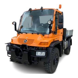
User Manuals: Unimog U500 Off-Roading Truck
Manuals and User Guides for Unimog U500 Off-Roading Truck. We have
1
Unimog U500 Off-Roading Truck manual available for free PDF download: Mounting Manuallines
Unimog U500 Mounting Manuallines (292 pages)
BODY & IMPLEMENT
Brand:
Unimog
| Category:
Utility Vehicle
| Size: 23 MB
Table of Contents
Table of Contents
0
Table of Contents
6
General Information
12
Introduction
12
Emission, Noise and Safety
14
Identification
16
Requirements for Implement Mounting and Operating
17
Instructions
17
Warranty Rights
17
Maintenance Instructions
17
Corrosion Protection Measures
18
Accident Prevention
18
Recycling - Re-Use of Components
19
Product Liability
19
Damage Prevention and Safety Regulations
20
General Notes
20
Delivery of Chassis
20
Prevention of Accidents on the Vehicle
20
Plastic Compressed-Air, Fuel and Brake Lines
20
Welding Operations
21
Springs
22
Painting Procedures
22
Pushing and Towing
23
Electrical System
23
Mobile Communication Systems
24
Electromagnetic Compatibility (EMC)
24
Implement Drives
24
Applications
26
Front Mounted Mowers
26
Rear Mounted Mowers
27
Spreaders
28
Snow Plows
29
Wing Plow
30
Snow Cutters / Blowers
31
Suction Sweepers
32
Front Mounted Sweepers
33
Winches
34
Aerial Devices (man Lifts)
35
Cranes
36
Drill Devices
37
Front End Loaders
38
Front Mounted Devices
39
Sewer Cleaning Devices
40
Water Tanks
41
Front Mounted 3-Point Hitches
42
Rear Mounted 3-Point Hitches
43
Fire Bodies
44
Refuse Collection Vehicles
45
Box Bodies
46
Wood Chipper (Front Mounted)
47
Concrete Mixers
48
Diggers / Excavators
49
Skip Loader
50
Rear Mounted Small Cranes
51
Vehicle Information
53
General Technical Data
53
Technical Data of Implement Drives
55
Mechanical Drives
55
Hydraulic Drives
55
Vehicle Drawings
56
U500 NA, Wheelbase: 131.89 in / 3,350 MM
56
U500 NA, Wheelbase: 153.54 in / 3,900 MM
58
Implement / Body Installation
61
General Notes
61
Free Movement of Implements/Bodies on the Chassis
61
Vehicle Modifications
62
Dimensions and Weight Specifications
63
Weight Distribution
64
Suspension Graph
64
Coordinate Systems
67
Center of Gravity
68
General Information
68
Determination of the Center of Gravity
68
Chassis Center of Gravity
73
Permissible Height of Center of Gravity
73
Anti-Roll Bars
74
General Notes on Vehicle Components
74
Tires
74
Cooling
75
Engine Air Intake
75
Exhaust System
75
Springs
76
Brake System
76
Maintenance and Repair
76
Secure Mounting of Implements / Counterweights
77
Bodies with Changing Overall Center of Gravity
79
Static Check
79
Dynamic Check
80
Mounting of Implements
81
Front Mounting of Implements
82
General Notes to Front Mounting
82
Front Mounting Plate
82
Integrated Implement Support
86
Permitted Implement Weights; Permitted Forces and ......... Torques on the Front Mounting Plate
89
Front End Dimensions
89
Center Mounting of Implements and Bodies
90
Bodies/Implements with Variable Overall C.o.g
90
Bodies/Implements on the Platform
93
Bodies/Implements on the Ball Points
106
Dimensioning of Implement Mounting Frames
120
Bodies/Implements Directly Mounted at the Chassis
130
Frame Without Outriggers (E.g. Shelters, Fire Bodies
130
Bodies/Implements with Outriggers
138
Mounting Space under the Cab
157
Implement Mounting between the Axles
157
Rear Mounting of Implements and Bodies
163
Mechanical Drive of Implements
165
Notes on the Transmission Ratio
165
General Notes on Mechanical Implement Drives
165
Overview of Available Mechanical Pto's for Unimog
166
Safety Instructions for Mechanical Implement Drives
166
Overview and Positions of Power Take-Offs
167
Maximum Available Power Output of the Pto's
168
Engine Controls and Speed Settings
168
Engine Dependent Power Take-Off (Code N05)
169
Technical Data for N05 Auxiliary Power Take-Off
169
Vibration Absorber
171
Power Take-Off Shaft Drive (Code N08)
173
General Notes
173
Usable Power Output of the Power Take-Off Shaft
174
Technical Data of Power Take-Off Shaft Drive N08
175
Power Take-Off Shaft Profile (According to SAE J499A)
175
Position of PTO Shaft
176
Calculation of the PTO Shaft Height above Ground
177
Auxiliary Power Take-Off Drives (Code N16/N19)
179
General Notes on Auxiliary Pto's (Code N16/N19)
179
Technical Data on Auxiliary Pto's (Code N16 / N19)
179
Hydraulic Pumps for N16 Auxiliary Power Take-Off
182
Direct Flange Mounting on Auxiliary PTO N16
185
Drive Shafts for Implements
186
General Information on Drive Shafts
186
Angle of Deflection/Joint Angle "Β" of Drive Shafts
187
Forces in the Drive Shaft System
188
Assembly of the Drive Shaft
189
Bearing
189
Unbalance
189
Maintenance
189
Hydraulic System
191
Overview of Codes and Hydraulic Circuits on the Unimog194
191
Hydraulic Drives
191
Overview of Available Hydraulic Equipment
192
Hydraulic System
195
Oil Heating
195
Basic Hydraulics
196
Information to the Basic Hydraulic System
197
Shut-Off Valve
204
Volume Flows of the Basic Hydraulic Systems
204
Dealers for Hydraulic Couplings in the USA
207
Tema Parts List for Unimog Hydraulic Connectors
207
Information to the Power Hydraulic Systems
208
Power Hydraulic Flow Rates
208
Drawings of the Power Hydraulics
209
Front Connectors of the Power Hydraulic System
211
(Code H93 & H94)
211
Center Power Hydraulic Connections
211
Volume Flows of the Power Hydraulic Systems
212
Parts List for Power Hydraulic System
215
Dealer for Power Hydraulic Couplings in the USA
215
Further Information on Unimog Hydraulic Systems
216
Hydraulic Output / Standard Values
216
Electrical System
218
General Notes on the Electrical System
218
Technical Data of the Electrical System
218
Lighting
218
Electric Cables
220
Current Consumption - Auxiliary Consumers
221
Unimog Ground Points
223
Electrical Interfaces
223
Power Outlet in the Cab (E37)
223
Implement Socket at the Front of the Vehicle
224
Implement Socket on the Battery Box
225
Rear Trailer Socket
227
Engine Remote Control
228
Remote Control Functions
228
Examples for Designing an External Manual Control
230
Important Note for Engine Remote Controls
232
W Code Descriptions
232
Preparation for the Installation of Roof-Mounted
235
Auxiliary Headlights
235
Modification of the Raised Headlights Code L47
236
Road Speed Signal and Travel Dependent Signal
236
Electromagnetic Compatibility
237
Pneumatic Consumers
239
General Notes to Pneumatic Consumers
239
Technical Data of the Compressed Air System
239
Air Extraction
240
Air Extraction on Vehicles Without CTIS
240
Air Extraction on Vehicles with CTIS
240
Cab
246
General Notes
246
Tilting the Cab
246
Cable Passage into the Cab
248
Cable Passage through the Rear Wall of the Cab
248
Cable Passage through the Front Wall of the Cab
248
Pass-Through Plug
249
Important Notes on Cable Passages into the Cab
254
Mountings on the Cab
254
Roof Loads / Roof Bars
254
Aerial Mounting
259
Attaching of an Implement Control Console in the Cab
259
Chassis Frame Modifications
269
Chassis Frame Data
269
Chassis Frame Dimensions
269
Cross-Section of the Chassis Frame
269
Chassis Frame of the U500, Short Wheelbase
270
Chassis Frame of the U500, Long Wheelbase
271
Chassis Frame Material
272
Rear Cross Member
272
Wheel Chocks
272
Mounting of Implements
272
Drilling on the Frame
273
Bolted Connections
274
Welding on the Frame
275
General Notes for Welding on the Frame
275
Welding Preparation
276
Regulations for Seam Preparation
277
Welding Procedure
277
Seam Finishing
277
Frame Extensions
277
Design Instructions for Extending the Frame
278
Shortening of the Frame
280
Wheelbase Extensions
280
Appendix
282
Conversion Table
282
List of Abbreviations
283
Table of Figures
283
Table of Tables
290
Advertisement
Advertisement
Related Products
Unimog U3000 2006
Unimog U4000 2006
Unimog U5000 2006
Unimog Categories
Utility Vehicle
More Unimog Manuals
Login
Sign In
OR
Sign in with Facebook
Sign in with Google
Upload manual
Upload from disk
Upload from URL