Sign In
Upload
Manuals
Brands
TR-Electronic Manuals
Media Converter
COS-65
TR-Electronic COS-65 Manuals
Manuals and User Guides for TR-Electronic COS-65. We have
6
TR-Electronic COS-65 manuals available for free PDF download: User Manual, Assembly Instructions Manual
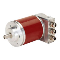
TR-Electronic COS-65 User Manual (155 pages)
Absolute Encoder
Brand:
TR-Electronic
| Category:
Media Converter
| Size: 6 MB
Table of Contents
Deutsch
3
Inhaltsverzeichnis
3
Table of Contents
3
Änderungs-Index
6
1 Allgemeines
7
Geltungsbereich
7
Referenzen
8
Verwendete Abkürzungen / Begriffe
9
2 Zusätzliche Sicherheitshinweise
10
Symbol- und Hinweis-Definition
10
Ergänzende Hinweise zur Bestimmungsgemäßen Verwendung
10
Organisatorische Maßnahmen
11
3 Ethernet/Ip™ Informationen
12
Allgemeines
12
Ethernet/Ip™ Übertragungsarten
13
Explicit Messaging, Austausch von Informationen
13
Implicit Messaging, Austausch von I/O-Daten
13
Ethernet/Ip™ Geräteprofile
14
Vendor ID
14
Weitere Informationen
14
4 Installation / Inbetriebnahmevorbereitung
15
Anschluss
16
Node-Adresse (Host-ID)
17
5 Inbetriebnahme
18
EDS-Datei
18
Bus-Statusanzeige
18
Link / Data Activity LED
18
Network-Status LED
19
Error LED
19
Netzwerkkonfiguration
20
MAC-Adresse
20
IP-Adresse
20
Subnetzmaske
20
Zusammenhang IP-Adresse und Default-Subnetzmaske
21
Default Gateway
21
6 Objekt-Modell
22
Objekt-Modell, Encoder Device
23
Classes
23
I/O Assembly Instances
24
I/O Assembly Data Attribute Format
24
7 Parametrierung
25
Klassen-Übersicht
26
Object 0X01, Identity
27
Gemeinsame Services
27
Class Attributes
27
Instance 1, Attributes
28
Attribute 0X05, Status
29
Behavior
30
Objekt-Spezifische Status Codes
32
Object 0X02, Message Router
34
Gemeinsame Services
34
Class Attributes
34
Instance 1, Attributes
35
Behavior
35
Object 0X04, Assembly
36
Gemeinsame Services
36
Class Attributes
36
Instance, Attributes
37
Attribute 0X03, Position 32
38
Attribute 0X03, Position 64
38
Connection Points
38
Object 0X06, Connection Manager
39
Gemeinsame Services
39
Class Attributes
39
Instance 1, Attributes
40
Instanz-Spezifische Service Codes
40
Object 0X23, Position Sensor
41
Gemeinsame Services
41
Class Attributes
41
Instance 1, Attributes
42
Attribute 0X02, Attribute List
43
Attribute 0X0B, Position Sensor Type
43
Attribute 0X0C, Direction Counting Toggle
44
Attribute 0X64, Position Value
44
Skalierungsparameter
45
Attribute 0X65, Total Measuring Range
46
Attribute 0X66/0X67, Revolution Numerator/Divisor
47
Attribute 0X68, Preset Value
50
Attribute 0X70, Accept Parameter
51
Object 0Xf4, Port
52
Gemeinsame Services
52
Class Attributes
52
Instance 1, Attributes
53
Instance 2, Attributes
54
Object 0Xf5, TCP/IP Interface
55
Gemeinsame Services
55
Class Attributes
55
Instance 1, Attributes
56
Attribute 0X01, Status
57
Attribute 0X02, Configuration Capability
57
Attribute 0X03, Configuration Control
57
Attribute 0X04, Physical Link Object
58
Attribute 0X05, Interface Configuration
58
IP-Parameter Beziehen
59
IP-Parameter Setzen und Speichern
60
Object 0Xf6, Ethernet Link
61
Gemeinsame Services
61
Class Attributes
61
Instance 1, Attributes
62
Attribute 0X02, Interface Flags
62
8 Verbindungstypen
63
9 Inbetriebnahme-Hilfen
64
IP-Parameter über DHCP-Server Beziehen
64
Voraussetzungen
64
Vorgehensweise
64
IP-Parameter über Trwinprog Programmieren und IM FLASH Speichern
67
Anbindung an den PC (Programmierung)
67
Programmierung
68
Lesen/Schreiben von Attributen über Rockwell Steuerung „Rslogix5000
69
Vorgehensweise
69
10 Fehlerursachen und Abhilfen
72
Optische Anzeigen
72
Allgemeine Status Codes
73
Sonstige Störungen
76
11 Anhang
77
Elementare Datentypen
77
English
81
Contents
81
Revision Index
84
1 General Information
85
Applicability
85
References
86
Abbreviations Used / Terminology
87
2 Additional Safety Instructions
88
Definition of Symbols and Instructions
88
Additional Instructions for Proper Use
88
Organizational Measures
89
3 Ethernet/Ip™ Information
90
General
90
Ethernet/Ip™ Transmission Types
91
Explicit Messaging, Exchange of Information's
91
Implicit Messaging, Exchange of I/O Data
91
Ethernet/Ip™ Device Profiles
92
Vendor ID
92
Further Information's
92
4 Installation / Preparation for Start-Up
93
Connection
94
Node Address (Host-ID)
95
5 Commissioning
96
EDS File
96
Bus Status Display
96
Link / Data Activity LED
96
Network Status LED
97
Error LED
97
Network Configuration
98
MAC-Address
98
IP-Address
98
Subnet Mask
98
Combination IP-Address and Default Subnet Mask
99
Default Gateway
99
6 Object Model
100
Object Model, Encoder Device
101
Classes
101
I/O Assembly Instances
102
I/O Assembly Data Attribute Format
102
7 Parameterization
103
Overview of Available Classes
104
Object 0X01, Identity
105
Common Services
105
Class Attributes
105
Instance 1, Attributes
106
Attribute 0X05, Status
107
Behavior
108
Object-Specific Status Codes
110
Object 0X02, Message Router
112
Common Services
112
Class Attributes
112
Instance 1, Attributes
113
Behavior
113
Object 0X04, Assembly
114
Common Services
114
Class Attributes
114
Instance, Attributes
115
Attribute 0X03, Position 32
116
Attribute 0X03, Position 64
116
Connection Points
116
Object 0X06, Connection Manager
117
Common Services
117
Class Attributes
117
Instance 1, Attributes
118
Instance-Specific Service Codes
118
Object 0X23, Position Sensor
119
Common Services
119
Class Attributes
119
Instance 1, Attributes
120
Attribute 0X02, Attribute List
121
Attribute 0X0B, Position Sensor Type
121
Attribute 0X0C, Direction Counting Toggle
122
Attribute 0X64, Position Value
122
Scaling Parameters
123
Attribute 0X65, Total Measuring Range
124
Attribute 0X66/0X67, Revolution Numerator/Divisor
125
Attribute 0X68, Preset Value
128
Attribute 0X70, Accept Parameter
129
Object 0Xf4, Port
130
Common Services
130
Class Attributes
130
Instance 1, Attributes
131
Instance 2, Attributes
132
Object 0Xf5, TCP/IP Interface
133
Common Services
133
Class Attributes
133
Instance 1, Attributes
134
Attribute 0X01, Status
135
Attribute 0X02, Configuration Capability
135
Attribute 0X03, Configuration Control
135
Attribute 0X04, Physical Link Object
136
Attribute 0X05, Interface Configuration
136
Obtaining of the IP Parameter
137
Set and Store the IP Parameter
138
Object 0Xf6, Ethernet Link
139
Common Services
139
Class Attributes
139
Instance 1, Attributes
140
Attribute 0X02, Interface Flags
140
8 Connection Type
141
9 Commissioning - Support
142
IP Configuration Via DHCP Server
142
Prerequisite
142
Procedure
142
IP Configuration with Trwinprog, FLASH Storage
145
Connection to the PC (Programming)
145
Programming
146
Read/Write of Attributes with Rockwell Control "Rslogix5000
147
Procedure
147
10 Causes of Faults and Remedies
150
Optical Displays
150
General Status Codes
151
Other Faults
154
11 Appendix
155
Elementary Data Types
155
Advertisement
TR-Electronic COS-65 User Manual (187 pages)
Absolute Encoder
Brand:
TR-Electronic
| Category:
Media Converter
| Size: 9 MB
Table of Contents
Deutsch
3
Inhaltsverzeichnis
3
Table of Contents
3
Änderungs-Index
6
1 Allgemeines
7
Geltungsbereich
7
Referenzen
8
Verwendete Abkürzungen / Begriffe
9
2 Zusätzliche Sicherheitshinweise
12
Symbol- und Hinweis-Definition
12
Ergänzende Hinweise zur Bestimmungsgemäßen Verwendung
12
Organisatorische Maßnahmen
13
3 POWERLINK Informationen
14
POWERLINK-Funktionsprinzip
14
Allgemeines
14
Slot Communication Network Management
15
POWERLINK - Zyklus, Zeitscheibenverfahren
16
MAC Adressierung
17
Protokoll
18
Geräteprofil
19
Referenz-Modell
20
Objektverzeichnis
21
Prozess- und Service-Daten-Objekte
21
Übertragung von SDO Nachrichten
22
Abort SDO Transfer Protokoll
23
PDO-Mapping
23
NMT State Machine
24
NMT CN State Machine
26
Nmt_Cs_Not_Active
27
Nmt_Cs_Pre_Operational_1
27
Nmt_Cs_Pre_Operational_2
27
Nmt_Cs_Ready_To_Operate
28
Nmt_Cs_Operational
28
Nmt_Cs_Stopped
29
Nmt_Cs_Basic_Ethernet
29
Zustände und Kommunikations-Objekt Beziehung
30
Weitere Informationen
31
4 Installation / Inbetriebnahmevorbereitung
32
Netzwerktopologie
33
Hubs
33
Jitter
33
Anschluss
34
EPL Node-ID
35
Einschalten der Versorgungsspannung
36
5 Inbetriebnahme
38
Error LED
39
Netzwerkkonfiguration
40
Zusammenhang IP-Adresse und Default-Subnetzmaske
41
IP-Adressierung
42
Hostname
43
6 Kommunikationsspezifische Standard-Objekte (Cia DS-301)
44
Objekt 1000H: Nmt_Devicetype_U32
45
Objekt 1001H: Err_Errorregister_U8
46
Objekt 100Ah: Nmt_Manufactswvers_Vs
47
Objekt 1020H: Cfm_Verifyconfiguration_Rec
49
Objekt 1030H: Nmt_Interfacegroup_0H_Rec
51
Objekt 1300H: Sdo_Sequlayertimeout_U32
54
Objekt 1A00H: Pdo_Txmappparam_0H_Au64
56
Objekt 1C0Ah: Dll_Cncollision_Rec
57
Objekt 1C0Bh: Dll_Cnlosssoc_Rec
58
Objekt 1C0Fh: Dll_Cncrcerror_Rec
60
Objekt 1C14H: Dll_Cnlossofsoctolerance_U32
61
Objekt 1E40H: Nwl_Ipaddrtable_0H_Rec
62
Objekt 1E4Ah: Nwl_Ipgroup_Rec
64
Objekt 1F82H: Nmt_Featureflags_U32
65
Objekt 1F83H: Nmt_Eplversion_U8
66
Objekt 1F93H: Nmt_Eplnodeid_Rec
67
Objekt 1F98H: Nmt_Cycletiming_Rec
68
Objekt 1F99H: Nmt_Cnbasicethernettimeout_U32
71
Objekt 1F9Ah: Nmt_Hostname_Vstr
72
7 Hersteller- und Profil-Spezifische Objekte (Cia DS-406)
73
Skalierungsparameter
74
Objekt 2002H: Messlänge in Schritten
75
Objekt 2000-2001H: Umdrehungen, Zähler/Nenner
76
Objekt 2003H: Presetwert
79
Objekt 2004H: Set_Preset
80
Objekt 2007H: Positionswert
81
Objekt 3100H: Mapping
82
8 Fehlerbehandlung
83
Fehlererfassung
85
Unterstützte Fehlermeldungen
86
Loss of Soc
87
Rx MAC Buffer Overflow / Tx MAC Buffer Underrun
88
Kollisionen
89
9 Fehlerursachen und Abhilfen
90
SDO Abort Codes
91
Error Codes
92
Error Register, Objekt 0X1001
93
English
97
Contents
97
Revision Index
100
1 General Information
101
Applicability
101
References
102
Abbreviations Used / Terminology
103
2 Additional Safety Instructions
106
Definition of Symbols and Notes
106
Additional Instructions for Proper Use
106
Organizational Measures
107
3 POWERLINK Information
108
POWERLINK Functional Principle
108
General
108
Slot Communication Network Management
109
POWERLINK - Cycle, Time Slot Principle
110
MAC Addressing
111
Protocol
112
Device Profile
113
Reference Model
114
Object Dictionary
115
Process and Service Data Objects
115
Transmission of SDO Messages
116
Abort SDO Transfer Protocol
117
PDO Mapping
117
NMT State Machine
118
NMT CN State Machine
120
Nmt_Cs_Not_Active
121
Nmt_Cs_Pre_Operational_1
121
Nmt_Cs_Pre_Operational_2
121
Nmt_Cs_Ready_To_Operate
122
Nmt_Cs_Operational
122
Nmt_Cs_Stopped
123
Nmt_Cs_Basic_Ethernet
123
States and Communication Object Relation
124
Further Information
125
4 Installation / Preparation for Commissioning
126
Network Topology
127
Hubs
127
Jitter
127
Connection
128
EPL Node-ID
129
Switching on the Supply Voltage
130
5 Commissioning
132
Device Description File
132
Bus Status Display
132
Indicator States and Flash Rates
132
Error LED
133
Status LED
133
Link / Data Activity LED, IN/OUT
133
Network Configuration
134
MAC-Address
134
IP-Address
134
Subnet Mask
134
Combination IP-Address and Default Subnet Mask
135
IP Addressing
136
Hostname
137
6 Communication-Specific Standard Objects (Cia DS-301)
138
Object 1000H: Nmt_Devicetype_U32
139
Object 1001H: Err_Errorregister_U8
140
Object 1006H: Nmt_Cyclelen_U32
140
Object 100Ah: Nmt_Manufactswvers_Vs
141
Object 1018H: Nmt_Identityobject_Rec
141
Object 1020H: Cfm_Verifyconfiguration_Rec
143
Object 1030H: Nmt_Interfacegroup_0H_Rec
145
Object 1300H: Sdo_Sequlayertimeout_U32
148
Object 1800H: Pdo_Txcommparam_0H_Rec
148
Object 1A00H: Pdo_Txmappparam_0H_Au64
150
Object 1C0Ah: Dll_Cncollision_Rec
151
Object 1C0Bh: Dll_Cnlosssoc_Rec
152
Object 1C0Fh: Dll_Cncrcerror_Rec
154
Object 1C14H: Dll_Cnlossofsoctolerance_U32
155
Object 1E40H: Nwl_Ipaddrtable_0H_Rec
156
Object 1E4Ah: Nwl_Ipgroup_Rec
158
Object 1F82H: Nmt_Featureflags_U32
159
Object 1F83H: Nmt_Eplversion_U8
160
Object 1F8Ch: Nmt_Currnmtstate_U8
160
Object 1F93H: Nmt_Eplnodeid_Rec
161
Object 1F98H: Nmt_Cycletiming_Rec
162
Object 1F99H: Nmt_Cnbasicethernettimeout_U32
165
Object 1F9Ah: Nmt_Hostname_Vstr
166
Object 1F9Eh: Nmt_Resetcmd_U8
166
TR-Electronic COS-65 User Manual (196 pages)
Rotary Encoder
Brand:
TR-Electronic
| Category:
Media Converter
| Size: 17 MB
Table of Contents
Deutsch
48
Table of Contents
48
Parametrierung und Konfiguration
76
Übersicht
77
Beschreibung der Betriebsparameter
90
Drehrichtung
90
Code SSI-Interface
90
Skalierungsparameter, C
90
Auflösung
91
Anzahl Umdrehungen
91
Skalierungsparameter, C
92
Messlänge in Schritten
92
Umdrehungen Zähler / Umdrehungen Nenner
93
Presetwert 1 / Presetwert 2
95
Nockenparameter
95
Format SSI-Interface
96
Kein Sonderformat
96
Parity Gerade
97
Parity Ungerade
97
Togglebit
97
Prüfsumme 28 nach 21-28 Datenbits
97
Datenbits SSI-Interface
99
Monozeit SSI-Interface
99
Preset-Justage-Funktion
100
Daten-Status Einschalten / Ausschalten
101
Daten-Status
102
Konfigurationsbeispiel, SIMATIC Manager
102
PROFINET Diagnose-Alarm
104
Optische Anzeigen
104
Störungsbeseitigung und Diagnosemöglichkeiten
104
Diagnose Alarm 1, Kanalspezifisch
105
Diagnose Alarm 2, Herstellerspezifisch
105
Diagnose über Record-Daten
107
Return of Submodul Alarm
107
Information & Maintenance
108
I&M0, 0Xaff0
108
Einbinden von Organisationsbausteinen (Obs)
109
Diagnosealarm-OB (ob 82)
109
Sonstige Störungen
109
English
113
Contents
113
Revision Index
115
Applicability
116
General Information
116
References
117
Abbreviations Used / Terminology
118
Additional Instructions for Proper Use
120
Additional Safety Instructions
120
Definition of Symbols and Instructions
120
Organizational Measures
121
Interface Information's
122
Profinet
122
Profinet Io
123
Real-Time Communication
124
Protocol
125
Distributed Clocks
126
PROFINET IO - Protocols
126
PROFINET IO - Services
126
PROFINET - Certificate, Further Information
127
PROFINET System Boot
127
SSI, Optional
128
Installation / Preparation for Commissioning
129
PROFINET - Interface
129
SSI - Interface, Optional
130
Cable Definition
131
Connection
132
PROFINET / Supply Voltage
132
Cams / External Hardware Inputs
133
Ssi
134
Commissioning
135
Re-Structuring and Versioning of the GSDML File
135
Device Description File (XML)
136
Device Identification
136
PROFINET IO Data Exchange
137
Distribution of IP Addresses
138
IP-Address
139
MAC-Address
139
Subnet Mask
139
Combination IP-Address and Default Subnet Mask
140
Bus Status Display
141
Parameterization and Configuration
142
Overview
143
Code SSI-Interface
156
Description of the Operating Parameters
156
Rotational Direction
156
Scaling Parameters, C
156
Resolution
157
Revolutions
157
Scaling Parameters, C
158
Total Measuring Range
158
Revolutions Numerator / Revolutions Denominator
159
Cam Parameters
161
Preset Value 1 / Preset Value 2
161
Format SSI-Interface
162
No Special Format
162
Check Sum 28 after 21-28 Data Bits
163
Parity Even
163
Parity Odd
163
Toggle Bit
163
Data Bits SSI-Interface
165
Mono Time SSI-Interface
165
Preset Adjustment Function
166
Switch-On / Switch-Off the Data Status
167
Configuration Example, SIMATIC Manager
168
Data Status
168
Optical Displays
170
PROFINET Diagnostic Alarm
170
Troubleshooting and Diagnosis Options
170
Diagnosis Alarm 1, Channel-Specific
171
Diagnosis Alarm 2, Manufacturer-Specific
171
Diagnostics Via Record Data
173
Return of Submodule Alarm
173
I&M0, 0Xaff0
174
Information & Maintenance
174
Diagnostic Alarm ob (ob 82)
175
Integration of Organization Blocks (Obs)
175
Other Faults
175
Advertisement
TR-Electronic COS-65 User Manual (103 pages)
Absolute Encoder CO*-65 series. PROFIBUS-DP. +SSI
Brand:
TR-Electronic
| Category:
Media Converter
| Size: 4 MB
Table of Contents
Deutsch
3
Inhaltsverzeichnis
3
Table of Contents
3
Änderungs-Index
5
1 Allgemeines
6
Geltungsbereich
6
Verwendete Abkürzungen / Begriffe
7
2 Zusätzliche Sicherheitshinweise
8
Symbol- und Hinweis-Definition
8
Ergänzende Hinweise zur Bestimmungsgemäßen Verwendung
8
Organisatorische Maßnahmen
9
3 Schnittstellen Informationen
10
Profibus
10
Kommunikationsprotokoll DP
10
Ssi
11
4 Installation / Inbetriebnahmevorbereitung
12
Anschluss - Hinweise
12
PROFIBUS - Schnittstelle
13
RS485 Übertragungstechnik
13
Bus-Terminierung
14
Bus-Adressierung
14
SSI - Schnittstelle (Optional)
15
RS422 Übertragungstechnik
15
Kabelspezifikation
16
Datenübertragung
17
Schirmauflage
18
5 Inbetriebnahme
20
Geräte-Stammdaten-Datei (GSD)
20
PNO-Identnummer
20
Anlauf am PROFIBUS
21
Bus-Statusanzeige
22
6 Konfiguration und Parametrierung
23
Übersicht
24
Konfiguration
25
PNO Class 1 16-Bit Resolution, Kennung 0Xd0
25
PNO Class 1 32-Bit Resolution, Kennung 0Xd1
25
PNO Class 2 16-Bit Resolution, Kennung 0Xf0
26
PNO Class 2 32-Bit Resolution, Kennung 0Xf1
26
TR-Mode Position, Kennung 0Xf1
27
TR-Mode Position+Rpm., Kennung 0Xf1, 0Xd0
28
Beschreibung der Betriebsparameter
29
Code Sequence (Zählrichtung)
29
Class 2 Functionality (Klasse 2 Funktionen)
29
Commissioning Diagnostics (Erweiterte Diagnosemeldung)
29
Scaling Function (Skalierungsfunktion)
29
Skalierungsparameter PNO CLASS 2
30
Measuring Units Per Revolution (Schritte Pro Umdrehung)
30
Total Measuring Range / Units (Messlänge in Schritten)
30
Skalierungsparameter TR-Modes
32
Total Measuring Range / Units (Messlänge in Schritten)
32
Revolutions Numerator / Denominator (Umdrehungen Zähler / Nenner)
33
SSI Code (Ausgabecode für SSI-Schnittstelle)
35
SSI Data Bit Count (Anzahl Datenbits SSI-Schnittstelle)
35
Profibus Code (Ausgabecode für PROFIBUS-Schnittstelle)
36
Preset Value 1 (1. Presetwert)
36
Preset Value 2 (2. Presetwert)
36
Commissioning Function (Inbetriebnahmefunktion)
36
Short Diagnostics (16 Byte) (Kurze Diagnose (16 Byte))
37
Limit Switch Lower and Upper Limit (Endschalter Unterer/Oberer Grenzw.)
37
Rpm. Multiplier (Geschwindigkeit [1/N U/Min])
37
Presetjustage
38
Optionale SSI-Schnittstelle
38
Konfigurationsbeispiel, SIMATIC Manager V5.1
39
7 Störungsbeseitigung und Diagnosemöglichkeiten
43
Optische Anzeigen, Leds
43
Verwendung der PROFIBUS Diagnose
44
Normdiagnose
44
Stationsstatus 1
44
Stationsstatus 2
44
Stationsstatus 3
44
Masteradresse
46
Herstellerkennung
46
Länge (in Byte) der Erweiterten Diagnose
46
Erweiterte Diagnose
47
Alarme
47
Betriebsstatus
48
Encodertyp
48
Singleturn Auflösung
48
Anzahl Auflösbarer Umdrehungen
48
Zusätzliche Alarme
48
Unterstützte Alarme
49
Warnungen
49
Unterstützte Warnungen
49
Profil Version
49
Software Version
50
Betriebsstundenzähler
50
Offsetwert
50
Herstellerspezifischer Offsetwert
50
Anzahl Schritte Pro Umdrehung
50
Messlänge in Schritten
50
Seriennummer
51
Herstellerspezifische Diagnosen
51
Sonstige Störungen
51
English
55
Contents
55
Revision Index
57
1 General Information
58
Applicability
58
Abbreviations Used / Terminology
59
2 Additional Safety Instructions
60
Definition of Symbols and Instructions
60
Additional Instructions for Proper Use
60
Organizational Measures
61
3 Interface Information's
62
Profibus
62
DP Communication Protocol
62
Ssi
63
4 Installation / Preparation for Commissioning
64
Connection - Notes
64
PROFIBUS - Interface
65
RS485 Data Transmission Technology
65
Bus Termination
66
Bus Address
66
SSI - Interface (Optional)
67
RS422 Data Transmission Technology
67
Cable Definition
68
Data Transmission
69
Shield Cover
70
5 Commissioning
72
Device Master File (GSD)
72
PNO ID Number
72
Starting up on the PROFIBUS
73
Bus Status Display
74
6 Configuration and Parameterization
75
Overview
76
Configuration
77
PNO Class 1 16-Bit Resolution, Identifier 0Xd0
77
PNO Class 1 32-Bit Resolution, Identifier 0Xd1
77
PNO Class 2 16-Bit Resolution, Identifier 0Xf0
78
PNO Class 2 32-Bit Resolution, Identifier 0Xf1
78
TR-Mode Position, Identifier 0Xf1
79
TR-Mode Position+Rpm., Identifier 0Xf1, 0Xd0
80
Description of the Operating Parameters
81
Code Sequence
81
Class 2 Functionality
81
Commissioning Diagnostics
81
Scaling Function
81
Scaling Parameter PNO CLASS 2
82
Measuring Units Per Revolution
82
Total Measuring Range / Units
82
Scaling Parameter TR-Modes
84
Total Measuring Range / Units
84
Revolutions Numerator / Revolutions Denominator
85
SSI Code
87
SSI Data Bit Count
87
Profibus Code
88
Preset Value 1
88
Preset Value 2
88
Commissioning Function
88
Short Diagnostics (16 Byte)
89
Limit Switch Lower and Upper Limit
89
Rpm. Multiplier [1/N Rpm]
89
Preset Adjustment
90
Optional SSI Interface
90
Configuration Example, SIMATIC Manager V5.3
91
7 Troubleshooting and Diagnosis Options
95
Optical Displays, Leds
95
Use of the PROFIBUS Diagnosis
96
Standard Diagnosis
96
Station Status 1
97
Station Status 2
97
Station Status 3
97
Master Address
98
Manufacturer's Identifier
98
Length (in Byte) of Extended Diagnosis
98
Extended Diagnosis
99
Alarms
99
Operating Status
100
Encoder Type
100
Single-Turn Resolution
100
Number of Resolvable Revolutions
100
Additional Alarms
100
Supported Alarms
101
Warnings
101
Supported Warnings
101
Profile Version
101
Software Version
102
Operating Hour Counter
102
Offset Value
102
Manufacturer-Specific Offset Value
102
Number of Increments Per Revolution
102
Measuring Length in Increments
102
Serial Number
103
Manufacturer-Specific Diagnostics
103
Other Faults
103
TR-Electronic COS-65 User Manual (55 pages)
Explosion Protection Enclosure
Brand:
TR-Electronic
| Category:
Enclosure
| Size: 4 MB
Table of Contents
Deutsch
3
Inhaltsverzeichnis
3
Table of Contents
3
Änderungs-Index
4
1 Allgemeines
5
Geltungsbereich
5
Verwendete Abkürzungen / Begriffe
6
2 Zusätzliche Sicherheitshinweise
7
Symbol- und Hinweis-Definition
7
Organisatorische Maßnahmen
7
Einsatz in Explosionsfähigen Atmosphären
8
3 Installation / Inbetriebnahmevorbereitung
9
Schnittstellenkombination Analog / SSI
9
Kabelspezifikation
9
Anschluss - Hinweise
10
Anbindung an den PC (Programmierung)
11
Analog - Schnittstelle, Grundfunktionalitäten
12
Mess-System-Variante mit Analog-Spannung
12
Mess-System-Variante mit Analog-Strom
14
4 Parametrierung über Trwinprog
16
Grundparameter
16
Zählrichtung
16
Skalierungsparameter
16
Messlänge in Schritten
17
Umdrehungen Zähler / Umdrehungen Nenner
17
Presetwert
20
Presetfreigabe
20
Messwertanfang
20
Analogausgang, Spannung
21
Datenart
21
Latch
21
Invertiert
21
Für die Positionsausgabe Gültige Parameter
22
Für die Drehzahlausgabe Gültige Parameter
23
Analogausgang, Strom
24
Datenart
24
Latch
24
Für die Positionsausgabe Gültige Parameter
25
Für die Drehzahlausgabe Gültige Parameter
26
Istwerte
27
Istwert
27
Drehzahl) 1/Min
27
5 Fehlerursachen und Abhilfen
27
English
31
Contents
31
Revision Index
32
1 General Information
33
Applicability
33
Abbreviations Used / Terminology
34
2 Additional Safety Instructions
35
Definition of Symbols and Instructions
35
Organizational Measures
35
Usage in Explosive Atmospheres
36
3 Installation / Preparation for Commissioning
37
Interface Combination Analog / SSI
37
Cable Definition
37
Connection - Notes
38
Connection to the PC (Programming)
39
Analog - Interface, Basic Functionalities
40
Measuring System Version with Analog-Voltage
40
Measuring System Version with Analog-Current
42
4 Parameterization Via Trwinprog
44
Basic Parameters
44
Count Direction
44
Scaling Parameters
44
Total Number of Steps
45
Revolutions Numerator / Revolutions Denominator
45
Preset Value
48
Preset Function
48
Origin Type
48
Analog Output, Voltage
49
Analog Position or Speed
49
Latch
49
Inverted
49
For the Position Output Valid Parameters
50
For the Speed Output Valid Parameters
51
Analog Output, Current
52
Analog Position or Speed
52
Latch
52
For the Position Output Valid Parameters
53
For the Speed Output Valid Parameters
54
Position Value
55
Speed 1/Min
55
5 Causes of Faults and Remedies
55
TR-Electronic COS-65 Assembly Instructions Manual (43 pages)
rotary encoder
Brand:
TR-Electronic
| Category:
Media Converter
| Size: 8 MB
Table of Contents
Deutsch
3
Inhaltsverzeichnis
3
Table of Contents
3
Änderungs-Index
4
1 Allgemeines
5
Geltungsbereich
5
Mitgeltende Dokumente
5
EU-Konformitätserklärung
5
Verwendete Abkürzungen und Begriffe
6
Allgemeine Funktionsbeschreibung
7
Absolut Encoder
7
Inkremental Encoder
8
2 Grundlegende Sicherheitshinweise
9
Symbol- und Hinweis-Definition
9
Verpflichtung des Betreibers vor der Inbetriebnahme
9
Allgemeine Gefahren bei der Verwendung des Produkts
10
Bestimmungsgemäße Verwendung
10
Bestimmungswidrige Verwendung
10
Gewährleistung und Haftung
11
Organisatorische Maßnahmen
11
Personalauswahl und -Qualifikation; Grundsätzliche Pflichten
12
Sicherheitstechnische Hinweise
12
3 Transport / Lagerung
13
4 Montagehinweise / Schema
14
Vollwelle
14
Flansch-Montage
14
Klemmflansch-Montage
14
Spannpratzen-Montage
15
Servoklammern-Montage
15
Sackloch
16
Montage mit Drehmomentstütze
16
Montage mit Stift-Nut
17
Kupplung
18
Montage mit Kupplung
18
5 Zubehör
21
English
25
Contents
25
Revision Index
26
1 General Information
27
Scope
27
Other Applicable Documents
27
EU Declaration of Conformity
27
Abbreviations and Definitions
28
General Functional Description
29
Absolute Encoder
29
Incremental Encoder
30
2 Basic Safety Instructions
31
Definition of Symbols and Instructions
31
Obligation of the Operator before Start-Up
31
General Risks When Using the Product
32
Intended Use
32
Non-Intended Use
32
Warranty and Liability
33
Organizational Measures
33
Personnel Qualification; Obligations
34
Safety Informations
34
3 Transportation / Storage
35
4 Instructions for Mounting / Schematic
36
Solid Shaft
36
Flange Mounting
36
Clamping Flange
36
Clamping Brackets
37
Servo Clamps
37
Blind Shaft
38
Mounting with Torque Holder
38
Mounting with Pin-Groove
39
Integrated Claw Coupling
40
Mounting with Coupling
40
5 Accessories
43
Advertisement
Related Products
TR Electronic COS-58
TR-Electronic SERCOS COS-58
TR-Electronic COS58M-131072/4096 PBS SACKHW10
TR-Electronic COS582M-18BIT/4096 EPN DMS 10H7 KRF
TR-Electronic COV-65
TR Electronic COV-58
TR Electronic COH-58
TR-Electronic SERCOS COK-58
TR Electronic COH-1102
TR-Electronic COV582M-18BIT/4096 EIP 36ZB10FL
TR-Electronic Categories
Media Converter
Transducer
Measuring Instruments
Enclosure
DC Drives
More TR-Electronic Manuals
Login
Sign In
OR
Sign in with Facebook
Sign in with Google
Upload manual
Upload from disk
Upload from URL