Sign In
Upload
Manuals
Brands
Sun Microsystems Manuals
Server
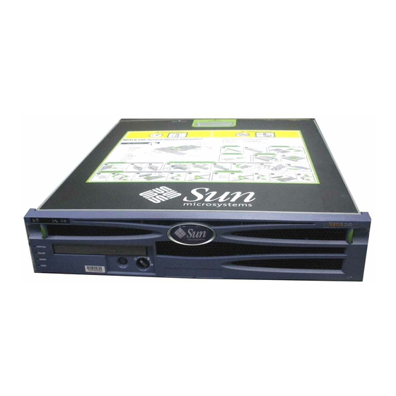
Netra 240
Sun Microsystems Netra 240 Manuals
Manuals and User Guides for Sun Microsystems Netra 240. We have
2
Sun Microsystems Netra 240 manuals available for free PDF download: Service Manual, Installation Manual
Sun Microsystems Netra 240 Service Manual (154 pages)
Brand:
Sun Microsystems
| Category:
Server
| Size: 8 MB
Table of Contents
Table of Contents
3
Preface
15
Identifying the Netra 240 Server Components and Leds
19
Identifying the Netra 240 Server Components
19
TABLE 1-1 Locating Illustrations and Service Instructions for Netra 240 Server Components
20
FIGURE 1-1 Front Panel Components
21
FIGURE 1-2 Rotating Service Module - Miscellaneous Internal Components and Rear Panel Components
22
FIGURE 1-3 Hardware Cryptographic Module and Memory
23
Optional Components
24
FIGURE 1-4 Processor Fans and Heat Sink Assemblies on a Replacement System Board
24
TABLE 1-2 Optional Components
25
TABLE 1-3 Supported PCI Cards
25
Identifying the Netra 240 Server LED Indicators
26
Front Panel Indicators
26
FIGURE 1-5 Location of the Front Panel Indicators
26
TABLE 1-4 Server Status Indicators (Front and Rear Panels)
27
TABLE 1-5 Alarm Indicators and Dry Contact Alarm States
28
Rear Panel Indicators
30
FIGURE 1-6 Hard Drive Indicators
30
TABLE 1-6 Hard Drive Indicators
30
FIGURE 1-7 Rear Panel Indicators
31
FIGURE 1-8 Ethernet Network Indicators
31
TABLE 1-7 Network Link Indicators
31
TABLE 1-8 Network Speed Indicators
32
TABLE 1-9 Power Supply Unit Indicators
32
Preparing to Service the System
33
Tip Warning
33
Controlling Server Power
34
FIGURE 2-1 Netra 240 Server Tip Hazard
34
FIGURE 2-2 On/Standby Button and Rotary Switch
35
TABLE 2-1 On/Standby Button Power States, Actions, and Results
36
FIGURE 2-3 Rotary Switch Positions
37
TABLE 2-2 Rotary Switch Positions and Server Behaviors
37
Powering on the Server
38
TABLE 2-3 System Control Rotary Switch Functions and Positions
38
FIGURE 2-4 Finger Holds on the Bezel
39
Powering on the Server Remotely
40
Powering off the Server
40
Powering off the Server Remotely
41
Powering off the System from the Ok Prompt
41
Powering off the System from the ALOM System Controller Prompt
42
Initiating a Reconfiguration Boot
42
Accessing Internal Components
45
Removing the Server Cover
45
FIGURE 2-5 Removing the Server Cover
46
Installing the Server Cover
47
FIGURE 2-6 Two Methods of Hanging the Detached Cover on a Netra 240 Server
47
Accessing Rotating Service Module Components
48
Opening the Rotating Service Module
48
Closing the Rotating Service Module
49
FIGURE 2-7 Opening the Rotating Service Module
49
Avoiding Electrostatic Discharge
50
FIGURE 2-8 Grounding Point in the Server
50
Removing and Replacing Front and Rear Panel Components
51
Bezel Assembly
52
Removing the Bezel Assembly
52
FIGURE 3-1 Finger Holds on the Bezel
52
Installing the Bezel Assembly
53
FIGURE 3-2 Disconnecting the Bezel Cables
53
Air Filter
54
Removing the Air Filter
54
Installing the Air Filter
55
FIGURE 3-3 Removing and Replacing the Air Filter from the Bezel
55
System Configuration Card
56
Removing a System Configuration Card
56
Inserting a System Configuration Card
57
FIGURE 3-4 Removing and Inserting a System Configuration Card
57
Hard Drives
58
Removing a Hard Drive
58
Installing a Hard Drive
61
FIGURE 3-5 Removing and Installing a Hard Drive
61
DVD Drive
63
Removing a DVD Drive
64
FIGURE 3-6 Removing a DVD Drive
64
Installing a DVD Drive
65
FIGURE 3-7 Location of the DVD Drive Slot with a Filler Panel
66
Power Supply Unit
67
Removing a Power Supply Unit
67
Installing a Power Supply Unit
68
FIGURE 3-8 Removing a Power Supply Unit
68
Removing and Replacing Rotating Service Module Components
71
Alarm Board
72
Removing the Alarm Board
72
Installing the Alarm Board
73
FIGURE 4-1 Removing the Alarm Board
73
Front Fan Assembly Tray
74
Removing the Front Fan Assembly Tray
74
Installing the Front Fan Assembly Tray
75
FIGURE 4-2 Removing the Front Fan Assembly Tray
75
SCSI Interface Board
76
Removing the SCSI Interface Board
76
FIGURE 4-3 Removing the SCSI Interface Board
77
Installing the SCSI Interface Board
78
System Configuration Card Reader Cluster
79
Removing the System Configuration Card Reader Cluster
79
FIGURE 4-4 Lifting the SCSI/IDE Cable Clamp
80
FIGURE 4-5 Removing the SCSI Interface Board Cable and the IDE Cable from the System Board
81
FIGURE 4-6 Removing the System Configuration Card Reader Cluster
82
Installing the System Configuration Card Reader Cluster
83
Removing and Replacing Miscellaneous Internal Components
85
Air Duct and Rear Fan Assembly
86
Removing or Rotating the Air Duct and Rear Fan Assembly
86
FIGURE 5-1 Removing/Rotating the Air Duct and Rear Fan Assembly
87
Installing or Closing the Air Duct and Rear Fan Assembly
88
Memory Modules
88
FIGURE 5-2 System Board Cpus and Corresponding Memory Locations
89
Removing Memory Modules
90
FIGURE 5-3 Removing and Inserting Memory
91
Installing Memory Modules
92
Memory Configuration Rules
92
TABLE 5-1 DIMM Pair Installation Order for a Single-Processor Server
92
TABLE 5-2 DIMM Pair Installation Order for a Dual-Processor Server
92
PCI Cards
94
Removing a PCI Card
95
FIGURE 5-4 Location of the PCI Lockdown Screw
95
FIGURE 5-5 Location of the PCI Lockdown Bracket
96
FIGURE 5-6 Removing and Installing the Upper Half-Length PCI Cards
97
Installing a PCI Card
98
FIGURE 5-7 Removing and Installing the Lower Full-Length PCI Card
98
Power Distribution Board
99
Removing the Power Distribution Board
99
FIGURE 5-8 Removing the Power Distribution Board
100
FIGURE 5-9 Disengaging a Power Supply Unit
101
Installing the Power Distribution Board
102
Hardware Cryptographic Module
103
Removing the Hardware Cryptographic Module
103
FIGURE 5-10 Removing and Installing the Hardware Cryptographic Module
104
Installing the Hardware Cryptographic Module
105
System Board Assembly
105
Removing the System Board
105
FIGURE 5-11 Removing the PCI Riser Card Assembly
106
FIGURE 5-12 Disconnecting the PDB Wiring Harness from the System Board
107
FIGURE 5-13 Lifting the SCSI/IDE Cable Clamp
108
FIGURE 5-14 Removing the SCSI Interface Board Cable and the IDE Cable from the System Board
109
FIGURE 5-15 Detaching the Front Fan Assembly Cables from the System Board Connectors
110
FIGURE 5-16 Removing the DB-9 and SCSI Jackposts from the Server
111
FIGURE 5-17 Removing and Installing a System Board
112
Installing a System Board
113
FIGURE 5-18 Location of the CPU Heat Sink Assemblies
113
FIGURE 5-19 Detaching the Fan Power Cables
114
FIGURE 5-20 Unlocking the Heat Sink Fasteners
115
FIGURE 5-21 Lifting the Heat Sink from the CPU Socket
116
FIGURE 5-22 Removing the Heat Sink Fans
117
FIGURE 5-23 Replacing the Heat Sink on the CPU Socket
118
System Board Jumper Settings
121
TABLE 6-1 Default Jumper Settings
121
FIGURE 6-1 Location of Jumpers on the Netra 240 System Board
123
Illustrated Parts Breakdown
125
Front Panel Components
126
FIGURE A-1 Illustrated Parts Breakdown, Front Panel Components
126
TABLE A-1 Part Numbers for Front Panel Components
126
Rotating Service Module, Internal and Rear Panel Components
128
FIGURE A-2 Illustrated Parts Breakdown, Rotating Service Module, Internal and Rear Panel Components
128
TABLE A-2 Part Numbers for Rotating Service Module, Internal and Rear Panel Components
128
Miscellaneous Internal Components
130
FIGURE A-3 Illustrated Parts Breakdown, Miscellaneous Internal Components
130
TABLE A-3 Part Numbers for Miscellaneous Internal Components
131
Connector Pinouts
133
Gigabit Ethernet Ports
134
FIGURE B-1 Gigabit Ethernet Port Pin Numbering
134
TABLE B-1 Ethernet Connection Transfer Rates
134
TABLE B-2 Gigabit Ethernet Port Signals
134
Network Management Port
135
FIGURE B-2 Network Management Port Pin Numbering
135
TABLE B-3 Network Management Connector Signals
135
Serial Ports
136
Serial Management Port
136
TABLE B-4 Default Serial Connection Settings
136
RJ-45 to DB-9 Adapter Crossovers
137
FIGURE B-3 Serial Management Port Pin Numbering
137
TABLE B-5 Serial Management RJ-45 Connector Signals
137
TABLE B-6 RJ-45 to DB-9 Adapter Crossovers
137
RJ-45 to DB-25 Adapter Crossovers
138
Serial Port (10101)
138
FIGURE B-4 Serial Port (10101) Pin Numbering
138
TABLE B-7 RJ-45 to DB-25 Adapter Crossovers
138
TABLE B-8 Serial Port (10101) Connector Signals
138
Alarm Port
139
FIGURE B-5 Alarm Port Pin Numbering
139
TABLE B-9 Alarm Connector Signals
139
USB Ports
140
FIGURE B-6 USB Ports Pin Numbering
140
TABLE B-10 USB Connector Pin Signals
140
SCSI Port
141
FIGURE B-7 SCSI Port Pin Numbering
141
TABLE B-11 SCSI Port Pin Signals
141
System Configuration Card and Openboot Configuration Parameters
143
FIGURE C-1 Location of the System Configuration Card
143
TABLE C-1 Openboot PROM Configuration Parameters Stored on the System Configuration Card
144
Specifications
147
Physical Specifications
147
TABLE D-1 Physical Specifications of the Netra 240 Server
147
Environmental Requirements
148
TABLE D-2 DC Server Operating and Storage Specifications
148
TABLE D-3 AC Server Operating and Storage Specifications
148
Acoustic Noise Emissions
149
Electrical Specifications
149
TABLE D-4 DC Operating Power Limits and Ranges
149
TABLE D-5 AC Operating Power Limits and Ranges
149
NEBS Level 3 Compliance for the DC-Powered Server
150
Advertisement
Sun Microsystems Netra 240 Installation Manual (134 pages)
Brand:
Sun Microsystems
| Category:
Server
| Size: 5 MB
Table of Contents
Table of Contents
3
Preface
13
Using UNIX Commands
13
Shell Prompts
14
Typographic Conventions
14
Related Documentation
15
Accessing Sun Documentation
15
Third-Party Web Sites
15
Contacting Sun Technical Support
16
Sun Welcomes Your Comments
16
Introduction
17
Overview
18
FIGURE 1-1 Netra 240 Server
18
Features
19
Standard Server Configurations
19
TABLE 1-1 Netra 240 Server Standard Configurations
19
Shipment Contents
20
Sun Advanced Lights out Manager
20
TABLE 1-2 Contents of the Netra 240 Server Shipment
20
TABLE 1-3 ALOM Component Monitoring
21
Sun Install Check Tool
22
Sun Remote Services Net Connect Support
22
Installation Site Requirements
23
Physical Dimensions
23
TABLE 1-4 Physical Dimensions
23
Environmental Requirements
24
Recommended Operating Environment
24
TABLE 1-5 DC Server Operating and Storage Specifications
24
TABLE 1-6 AC Server Operating and Storage Specifications
24
Ambient Temperature
25
Ambient Relative Humidity
25
Airflow Considerations
25
Acoustic Noise Emissions
26
Calculating Heat Dissipation
26
NEBS Level 3 Compliance
27
Installation Overview
29
Installation Overview
30
Installing the Bezel Air Filter
31
FIGURE 2-1 Finger Holds on Bezel
32
FIGURE 2-2 Installing the Air Filter in the Front Bezel
32
Installing Optional Components
33
Mounting the Server into a Rack
35
Rackmounting Options
36
Hardmount in a 19-Inch 4-Post Rack
36
TABLE 3-1 Optional Rackmount Kits
36
FIGURE 3-1 Contents of the Hardmount 19-Inch 4-Post Kit
37
TABLE 3-2 19-Inch 4-Post Rackmount Screw Kit Contents
37
FIGURE 3-2 Securing the Hardmount Brackets to the Server
38
FIGURE 3-3 Attaching the Rear Mount Support Brackets
39
FIGURE 3-4 Securing the Front of the Server to the Rack
40
Sliding Rail Mount in a 19-Inch 4-Post Rack
41
FIGURE 3-5 Securing the Rear of the Server to the Rack
41
FIGURE 3-6 Contents of the Sliding Rail 19-Inch 4-Post Kit
42
TABLE 3-3 Sliding Rail 19-Inch 4-Post Rackmount Screw Kit Contents
42
FIGURE 3-7 Securing the Hardmount Bracket to the Server
43
FIGURE 3-8 Dismantling the Slide
44
FIGURE 3-9 Fixing the Glides to the System Chassis
45
FIGURE 3-10 Securing the Brackets to the Rack
46
FIGURE 3-11 Securing the Slide to the Brackets
47
FIGURE 3-12 Sliding the System into the Rack
48
FIGURE 3-13 Securing the Front of the System to the Rack
49
Hardmount in a 600 MM 4-Post Rack
50
FIGURE 3-14 Contents of the Hardmount 600 MM 4-Post Kit
50
FIGURE 3-15 Loosening the Adjustable Rail Screws
51
TABLE 3-4 Hardmount 600 MM 4-Post Rackmount Screw Kit Contents
51
FIGURE 3-16 Securing the Front of the Adjustable Rails to the Rack
52
FIGURE 3-18 Installing the Rear Flange Onto the Adjustable Rail
54
FIGURE 3-19 Securing the Side Rails to the Server
55
FIGURE 3-20 Sliding the Server Onto the Adjustable Rails
56
FIGURE 3-21 Securing the Rear of the Server to the Rear Flanges
57
FIGURE 3-22 Securing the Front of the Server to the Front of the Rack
58
Hardmount in a 23-Inch 2-Post Rack
59
FIGURE 3-23 Contents of the Hardmount 23-Inch 2-Post Kit
59
FIGURE 3-24 Securing the Side Brackets to the Side of the Server
60
TABLE 3-5 Hardmount 23-Inch 2-Post Rackmount Screw Kit Contents
60
FIGURE 3-25 Installing the Rail Guides in the Rack
61
FIGURE 3-26 Installing and Securing the Server in the 2-Post Rack
62
FIGURE 3-27 Installing a Screw on the Shallowest Rack Position on the Rear Plate
63
FIGURE 3-28 Installing the Rear Plate to the Side Bracket
64
FIGURE 3-29 Securing the Rear Plate to the Side Bracket
65
Hardmount in a 19-Inch 2-Post Rack
66
FIGURE 3-30 Contents of the Hardmount 19-Inch 2-Post Kit
66
TABLE 3-6 Hardmount 19-Inch 2-Post Rackmount Screw Kit Contents
66
FIGURE 3-31 Securing the Side Brackets to the Side of the Server
67
FIGURE 3-32 Installing and Securing the Server in the 2-Post Rack
68
FIGURE 3-33 Installing Screws on the Shallowest Rack Position on the Rear Plate
69
FIGURE 3-34 Installing the Rear Plate to the Side Bracket
70
FIGURE 3-35 Securing the Rear Plate to the Rack
71
Connecting the Data Cables
73
Rear Cable Connections
74
TABLE 4-1 Rear Cable Connector Descriptions
75
Connecting the Chassis Grounding Cable
76
FIGURE 4-3 Location of Chassis Grounding Studs
76
Connecting the Data Cables
77
Gigabit Ethernet Ports
77
TABLE 4-2 Ethernet Connection Transfer Rates
77
Network Management Port
78
FIGURE 4-5 Network Management Port Pin Numbering
78
TABLE 4-3 Gigabit Ethernet Port Signals
78
TABLE 4-4 Network Management Connector Signals
78
Serial Ports
79
Serial Management Port
79
TABLE 4-5 Default Serial Connection Settings
79
TABLE 4-6 Serial Management RJ-45 Connector Signals
80
TABLE 4-7 RJ-45 to DB-9 Adapter Crossovers
80
Serial Port (10101)
81
FIGURE 4-7 Serial Port (10101) Pin Numbering
81
TABLE 4-8 RJ-45 to DB-25 Adapter Crossovers
81
TABLE 4-9 Serial Port (10101) Connector Signals
81
Alarm Port
82
FIGURE 4-8 Alarm Port Pin Numbering
82
TABLE 4-10 Alarm Connector Signals
82
USB Ports
83
SCSI Port
83
FIGURE 4-9 USB Ports Pin Numbering
83
FIGURE 4-10 SCSI Port Pin Numbering
83
TABLE 4-11 USB Connector Pin Signals
83
TABLE 4-12 SCSI Port Pin Signals
84
Power Source Requirements and Connections
87
Operating Power Limits and Ranges
88
TABLE 5-1 DC Operating Power Limits and Ranges
88
TABLE 5-2 AC Operating Power Limits and Ranges
88
Estimated Power Consumption
89
TABLE 5-3 DC Server Power Consumption
89
TABLE 5-4 AC Server Power Consumption
89
DC Source Site Requirements
90
DC Supply and Ground Conductor Requirements
90
TABLE 5-5 DC Power Requirements
90
Overcurrent Protection Requirements
91
Assembling and Connecting the DC Input Power Cable
91
Assembling the DC Input Power Cable
91
FIGURE 5-1 DC Connection Parts
92
FIGURE 5-2 Stripping the Insulation from the Wire
93
FIGURE 5-3 Opening the DC Input Plug Cage Clamp Using the Cage Clamp Operating Lever
94
FIGURE 5-4 Opening the Cage Clamp Using a Screwdriver
94
Installing the Strain Relief Housings
95
FIGURE 5-5 Assembling the DC Input Power Cable
95
FIGURE 5-6 Inserting the Bottom Portion of the Strain Relief Housing
96
FIGURE 5-7 Routing the Wires out of the Bottom Portion of the Strain Relief Housing
96
FIGURE 5-8 Securing the Wires to the Strain Relief Housing
97
Connecting the DC Input Power Cable to the Server
98
FIGURE 5-9 Assembling the Strain Relief Housing
98
FIGURE 5-10 DC Connector Locations
99
FIGURE 5-11 Connecting the DC Input Power Cable to the DC Connectors
99
FIGURE 5-12 Disconnecting the DC Input Power Cable from the DC Connector
100
Connecting the AC Power Cables
101
FIGURE 5-13 Connecting the AC Power Cords to the AC Power Inlet Connectors
102
Setting up a System Console Device
103
Accessing the System Console through a Terminal Server
104
Connecting the Server to a Terminal Server
104
FIGURE 6-1 Patch Panel Connection between a Terminal Server and a Netra 240 Server
105
Accessing the System Console through a Terminal Server
106
TABLE 6-1 Pin Crossovers for Connecting to a Typical Terminal Server
106
Accessing the System Console through an Alphanumeric Terminal
107
Accessing the System Console through a TIP Connection
108
Powering on and Configuring the Server
111
Powering on the Server
112
Setting the Rotary Switch
112
FIGURE 7-1 Finger Holds on Bezel
112
Powering on from the Keyboard
113
FIGURE 7-2 Rotary Switch Set to Normal Position
113
Powering on Using the On/Standby Button
114
Powering off the System Using the On/Standby Button
115
Configuring the Server
116
Software Configuration Worksheet
116
TABLE 7-1 Netra 240 Software Configuration Worksheet
116
Configuring with the Server Details Registered as a Name Server
119
Configuring Without the Server Details Registered as a Name Server
120
Configuring a Standalone Server for the First Time
121
Clearing Your Configuration and Starting Again
121
Accessing Advanced Lights out Manager (ALOM) Software
122
Displaying the ALOM Prompt
122
Displaying the Console Prompt
123
Taking Console Write Capability Away from Another User
123
Server Status Indicators
125
Front Panel Indicators
126
FIGURE A-1 Location of the Front Indicators
126
TABLE A-1 Server Status Indicators (Front and Rear)
126
FIGURE A-2 Hard Drive Indicators
127
TABLE A-2 Hard Drive Indicators
127
Rear Panel Indicators
128
FIGURE A-3 Rear Indicators on the Netra 240 Server
128
TABLE A-3 Power Supply Unit Indicators
128
FIGURE A-4 Ethernet Network Indicators
129
TABLE A-4 Network Link Indicators
129
TABLE A-5 Network Speed Indicators
130
Advertisement
Related Products
Sun Microsystems Netra 210
Sun Microsystems Netra 20
Sun Microsystems Netra 440
Sun Microsystems Netra 1290
Sun Microsystems Netra
Sun Microsystems Netra X4450
Sun Microsystems Netra t 1125
Sun Microsystems Netra X4250
Sun Microsystems Netra 1120
Sun Microsystems Netra 1125
Sun Microsystems Categories
Server
Storage
Desktop
Computer Hardware
Adapter
More Sun Microsystems Manuals
Login
Sign In
OR
Sign in with Facebook
Sign in with Google
Upload manual
Upload from disk
Upload from URL