Sign In
Upload
Manuals
Brands
Sun Microsystems Manuals
Server
Netra X4250
Sun Microsystems Netra X4250 Manuals
Manuals and User Guides for Sun Microsystems Netra X4250. We have
1
Sun Microsystems Netra X4250 manual available for free PDF download: Service Manual
Sun Microsystems Netra X4250 Service Manual (196 pages)
Brand:
Sun Microsystems
| Category:
Server
| Size: 14 MB
Table of Contents
Table of Contents
5
Service Manual
1
Preface
19
Typographic Conventions
20
Related Documentation
21
Documentation Feedback
22
1 Sun Netra X4250 Server Overview
23
Product Description
23
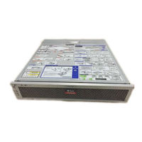
FIGURE 1-1 Sun Netra X4250 Server
23
Features at a Glance
24
Chassis Controls, Leds, and Connectors
26
Figure
26
Front Panel with DVD
26
Front Panel with Bezel Removed and Two Hdds
26
Front Panel with Bezel Removed and Four Hdds
27
Figure
27
Rear Panel Cable Connectors and Leds
27
Server Diagnostics Overview
28
Front and Rear Panel Leds
29
Server Leds
29
FIGURE 1-6 Location of the Bezel Server Status and Alarm Status Leds
30
FIGURE 1-8 Hard Drive Leds
33
Hard Drive Leds
33
Power Supply Leds
33
Ethernet Port Leds
34
FIGURE 1-10 Ethernet Port Leds
34
FIGURE 1-9 Power Supply Leds
34
Sun Integrated Lights out Manager (ILOM)
35
Memory Configuration
36
Memory Configuration and Fault Handling
36
POST and BIOS
36
Memory Fault Handling
37
2 Initial Inspection of the Server
39
Service Troubleshooting Flowchart
39
Gathering Service Information
40
System Inspection
40
Troubleshooting Power Problems
40
Externally Inspecting the Server
41
Internally Inspecting the Server
41
FIGURE 2-1 Server Front Panel
42
3 Preparing for Service
45
Safety Information
45
Electrostatic Discharge Safety
46
Safety Symbols
46
Use an Antistatic Mat
46
Use an Antistatic Wrist Strap
46
Required Tools
47
Prerequisite Tasks for Component Replacement
47
Powering off the Server
47
Emergency Shutdown
48
Disconnecting Cables from the Server
49
FIGURE 3-1 Slide Release Latches
50
Removing the Server from the Rack
50
FIGURE 3-2 Locating the Metal Lever
51
Performing Antistatic Measures
51
FIGURE 3-3 Top Cover and Release Button
52
Removing the Top Cover
52
FIGURE 3-4 Removing the PCI Mezzanine Cable and I/O Cables from the PCI Mezzanine
53
Removing the PCI Mezzanine
53
FIGURE 3-5 Removing Screws and Lifting the PCI Mezzanine
54
Field-Replaceable Units
55
FIGURE 3-6 Field-Replaceable Units
55
TABLE 3-1 Server FRU List
57
4 Replacing Storage Components
59
Replacing a Hard Drive
59
FIGURE 4-1 Opening the Bezel
60
Removing a Hard Drive
60
FIGURE 4-2 Locations of Hdds on 2 HDD Server
61
FIGURE 4-3 Locations of Hdds on 4 HDD Server
61
FIGURE 4-4 Opening Hard Drive Latch
62
FIGURE 4-5 Removing Hard Drive
63
Installing a Hard Drive
63
Replacing the Optical Media Drive
64
FIGURE 4-6 Installing the Hard Drive
64
Removing the Optical Media Drive
64
FIGURE 4-7 Releasing the Optical Media Drive
65
Installing the Optical Media Drive
65
Replacing the Media Bay Assembly
66
FIGURE 4-8 Inserting the Optical Media Drive
66
Removing the Media Bay Assembly
66
FIGURE 4-9 Media Bay Assembly Cables
67
FIGURE 4-10 Loosening the Media Bay Assembly Screws and Lifting from Chassis
68
FIGURE 4-11 Setting the Media Bay Assembly into Place and Tightening Screws
69
Installing the Media Bay Assembly
69
FIGURE 4-12 Connecting the Media Bay Assembly Cables
70
5 Replacing Motherboard Assembly Components
71
Replacing PCI-X and Pcie Cards
71
FIGURE 5-1 PCI Retainers and Corresponding Cards
72
Removing the PCI-X 4 and Pcie 5 Cards
72
Replacing PCI-X 4 and Pcie 5 Cards
72
FIGURE 5-2 Upper PCI Card Retainers and Securing Screws
73
FIGURE 5-3 Removing PCI-X 4 and Pcie 5 Cards from the PCI Mezzanine
74
FIGURE 5-4 Installing PCI-X 4 and Pcie 5 Cards in the PCI Mezzanine
75
Installing the PCI-X 4 and Pcie 5 Cards
75
Removing the PCI-X 3 Card
76
Replacing the PCI-X 3 Card
76
FIGURE 5-5 Removing the PCI-X 3 Card from the PCI Mezzanine
77
Installing the PCI-X 3 Card
77
FIGURE 5-6 Installing the PCI-X 3 Card in the PCI Mezzanine
78
Removing the Lower Pcie and SAS Controller Cards
79
Replacing the Lower Pcie or SAS Controller Cards
79
FIGURE 5-7 Removing Lower Pcie and SAS Controller Cards
80
Installing the Lower Pcie or SAS Controller Cards
81
FIGURE 5-8 Installing Lower Pcie and SAS Controller Cards
82
Replacing the Air Duct
83
Removing the Air Duct
83
FIGURE 5-9 Removing the Air Duct
84
Installing the Air Duct
84
FIGURE 5-10 Installing the Air Duct
85
Replacing FB-Dimms
86
FIGURE 5-11 Remind Button
86
Identifying Faulty FB-Dimms
86
FB-DIMM Guidelines
87
FIGURE 5-12 FB-DIMM Layout
88
TABLE 5-1 FB-DIMM Branch Number, Channel Number,And ILOM Address
88
Removing FB-Dimms
89
FIGURE 5-13 Removing FB-Dimms
90
Installing FB-Dimms
91
FIGURE 5-14 Installing FB-Dimms
92
Installing Additional FB-Dimms
93
Replacing the Battery
93
Removing the Battery
94
FIGURE 5-15 Prying the Battery from the Motherboard
95
Installing the Battery
95
FIGURE 5-16 Inserting the Battery into the Service Processor Board
96
Replacing the Motherboard Assembly
97
Removing the Motherboard Assembly
97
FIGURE 5-17 Removing the Cables Connected to the Motherboard
98
FIGURE 5-18 Removing the Motherboard Assembly Screws
99
FIGURE 5-19 Removing the Motherboard Assembly from the Chassis
100
FIGURE 5-20 Installing the Motherboard Assembly into the Chassis
100
Installing the Motherboard Assembly
100
FIGURE 5-21 Installing the Motherboard Assembly Screws
101
FIGURE 5-22 Reconnecting the Cables to the Motherboard Assembly
102
Removing a CPU
103
Replacing Cpus
103
Installing a CPU FRU
104
Installing an Optional CPU
105
Resetting Passwords and Clearing CMOS NVRAM
106
Resetting a BIOS Password Using a Jumper
106
Resetting BIOS Password from the BIOS Screen
106
Resetting CMOS NVRAM Using a Jumper
107
6 Replacing Chassis Components
109
Replacing the Air Filter
109
Removing the Air Filter
109
FIGURE 6-1 Opening the Bezel and Removing the Air Filter
110
Installing the Air Filter
110
Replacing a Power Supply
111
FIGURE 6-2 Installing the Air Filter and Closing the Bezel
111
FIGURE 6-3 Locating the Power Supplies and Latches
112
Removing a Power Supply
112
FIGURE 6-4 Removing a Power Supply
113
Installing a Power Supply
113
Replacing the System Fan Assembly
114
FIGURE 6-5 Installing a Power Supply
114
Removing the System Fan Assembly
114
FIGURE 6-6 Disconnecting the System Fan Assembly Cable
115
FIGURE 6-7 Lifting the System Fan Assembly from the Chassis
116
Installing the System Fan Assembly
116
Replacing the Hard Drive Fan Assembly
117
FIGURE 6-8 Installing the System Fan Assembly into the Chassis
117
Removing the Hard Drive Fan Assembly
117
FIGURE 6-9 Disconnecting the Hard Drive Fan Assembly Cable
118
FIGURE 6-10 Releasing the Hard Drive Fan Bracket
119
FIGURE 6-11 Lifting out the Hard Drive Fan Assembly
120
Installing the Hard Drive Fan Assembly
120
Replacing the FB-DIMM Fan Assembly
121
FIGURE 6-12 Lowering the Hard Drive Fan Assembly and Connecting the Cable
121
Installing the FB-DIMM Fan Assembly
122
Removing the FB-DIMM Fan Assembly
122
Replacing the Alarm Board
122
Removing the Alarm Board
122
FIGURE 6-13 Disconnecting the Cables from the Alarm Board
123
FIGURE 6-14 Removing the Alarm Board Screws and Removing from the Chassis
124
Installing the Alarm Board
124
Replacing the LED Board
125
FIGURE 6-15 Reconnecting the Alarm Board Cables
125
Removing the LED Board
125
FIGURE 6-16 Removing the LED Board
126
FIGURE 6-17 Disconnecting Cable from the LED Board
127
Installing the LED Board
127
FIGURE 6-18 Connecting Cable to the LED Board
128
FIGURE 6-19 Inserting the LED Board Tab and Tightening the Thumbscrew
129
Replacing the Power Distribution Board
130
Removing the Power Distribution Board
130
FIGURE 6-20 Removing the PDB Screws
131
FIGURE 6-21 Lifting the PDB from the Chassis
132
Installing the Power Distribution Board
132
7 Finishing up
135
Tasks for Finishing up
135
Installing the PCI Mezzanine
135
FIGURE 7-1 Lowering the PCI Mezzanine and Tightening the Screws
136
FIGURE 7-2 Reconnecting the PCI Mezzanine Cable
137
FIGURE 7-3 Installing Top Cover
137
Reinstalling the Server Chassis in the Rack
138
Removing Antistatic Measures
138
FIGURE 7-4 Returning the Server to the Rack
139
FIGURE 7-5 Release Levers
140
FIGURE 7-6 Installing the CMA
141
Powering on the Server
141
Reconnecting Cables to the Server
141
FIGURE 7-7 Powering on the Server
142
Signal Pinouts
143
Gigabit Ethernet Ports
143
Network Management Port
144
FIGURE A-1 Gigabit Ethernet Port Pin Numbering
144
FIGURE A-2 Network Management Port Pin Numbering
144
TABLE A-2 Gigabit Ethernet Port Signals
144
TABLE A-3 Network Management Connector Signals
145
TABLE A-4 Default Serial Connection Settings
145
Serial Port
146
FIGURE A-3 Serial Management Port Pin Numbering
146
RJ-45 to DB-9 Adapter Crossovers
146
TABLE A-5 Serial Management RJ-45 Connector Signals
146
TABLE A-6 RJ-45 to DB-9 Adappter Crossovers
146
RJ-45 to DB-25 Adapter Crossovers
147
Video Connector
147
Alarm Port
148
FIGURE A-5 Alarm Port Pin Numbering
148
TABLE A-8 Video Connector Signals
148
USB Ports
149
FIGURE A-6 USB Ports Pin Numbering
149
TABLE A-9 Alarm Connector Signals
149
TABLE A-10 USB Connector Pin Signals
150
Configuring BIOS and POST
151
BIOS Considerations
152
Peripheral Component Interconnect (PCI) Card Slot Booting Priority
152
NIC Naming
153
B.3 BIOS Setup Screens
154
Sun Netra X4250 Server NIC Booting Priority
154
TABLE B-2 BIOS Setup Screens Summary
154
Advanced
155
Boot
155
Exit
155
FIGURE B-2 BIOS Utility Menu Tree
155
Main
155
Security
155
Server
155
BIOS Setup Screens
156
BIOS Setup Menu Screens
156
BIOS Main Menu Screens
156
FIGURE B-3 BIOS Setup Utility: Main - System Overview
156
Section B.3.1.1, "BIOS Main Menu Screens
156
BIOS Advanced Menu Screens
157
FIGURE B-4 BIOS Setup Utility: Main - Product Information
157
Section B.3.1.2, "BIOS Advanced Menu Screens
157
FIGURE B-5 BIOS Setup Utility: Advanced
158
FIGURE B-6 BIOS Setup Utility: Advanced - CPU Settings
158
FIGURE B-7 BIOS Setup Utility: Advanced - System Memory Settings
159
FIGURE B-8 BIOS Setup Utility: Advanced - IDE Configuration
159
FIGURE B-9 BIOS Setup Utility: Advanced - Super IO Configuration
160
FIGURE B-10 BIOS Setup Utility: Advanced - Trusted Computing
160
FIGURE B-11 Bios Setup Utility: Advanced - USB Configuration
161
FIGURE B-13 BIOS Setup Utility: Advanced- PCI Configuration
162
FIGURE B-14 BIOS Setup Utility: Advanced- MPS Configuration
162
BIOS Boot Menu Screens
163
FIGURE B-15 BIOS Setup Utility: Advanced- Event Log Configuration
163
Section B.3.1.3, "BIOS Boot Menu Screens
163
FIGURE B-16 BIOS Setup Utility: Boot
164
FIGURE B-17 BIOS Setup Utility: Boot Settings Configuration
164
FIGURE B-18 BIOS Setup Utility: Boot Device Priority
165
FIGURE B-19 BIOS Setup Utility: Boot Hard Drives
165
BIOS Server Menu Screens
166
FIGURE B-20 BIOS Setup Utility: Boot CD/DVD Drives
166
Section B.3.1.4, "BIOS Server Menu Screens
166
FIGURE B-21 BIOS Setup Utility: Server
167
FIGURE B-22 BIOS Setup Utility: Server - Bottom of Scroll
167
FIGURE B-23 BIOS Setup Utility: Server - LAN Configuration
168
FIGURE B-24 BIOS Setup Utility: Server - LAN Configuration - Reset SP (BMC) Password
168
FIGURE B-25 BIOS Setup Utility: Server - Enable Remote Access
169
FIGURE B-26 Bios Setup Utility: Server - View SP Event Log
169
BIOS Security Menu Screens
170
FIGURE B-27 BIOS Setup Utility: Server - Clear SP Event Log
170
Section B.3.1.5, "BIOS Security Menu Screens
170
BIOS Exit Menu Screens
171
FIGURE B-28 BIOS Setup Utility: Security -Menu
171
Section B.3.1.6, "BIOS Exit Menu Screens
171
FIGURE B-29 BIOS Setup Utility: Exit
172
FIGURE B-30 BIOS Setup Utility: Exit - Save Configuration Changes
172
FIGURE B-31 BIOS Setup Utility: Exit - Discard Changes
173
FIGURE B-32 BIOS Setup Utility: Exit - Discard Changes, Do Not Exit
173
FIGURE B-33 BIOS Setup Utility: Exit - Load Optimal Defaults
174
FIGURE B-34 BIOS Setup Utility: Exit - Load Fail-Safe Defaults
174
Viewing Event Logs
175
FIGURE B-35 Event Log Screen
176
FIGURE B-36 SP Watch Dog Timer Options Screen
177
How BIOS POST Memory Testing Works
178
Redirecting Console Output
178
Changing POST Options
180
POST Codes
181
TABLE B-3 POST Codes
181
POST Code Checkpoints
183
TABLE B-4 POST Code Checkpoints
183
Power-On Self-Test (POST
177
Advertisement
Advertisement
Related Products
Sun Microsystems Netra X4200 M2
Sun Microsystems Netra X4450
Sun Microsystems Netra 440
Sun Microsystems Netra 1290
Sun Microsystems Netra
Sun Microsystems Netra 210
Sun Microsystems Netra t 1125
Sun Microsystems Netra 20
Sun Microsystems Netra 1120
Sun Microsystems Netra 1125
Sun Microsystems Categories
Server
Storage
Desktop
Computer Hardware
Adapter
More Sun Microsystems Manuals
Login
Sign In
OR
Sign in with Facebook
Sign in with Google
Upload manual
Upload from disk
Upload from URL