Sign In
Upload
Manuals
Brands
Sun Microsystems Manuals
Server
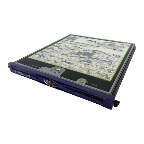
Netra 210
Sun Microsystems Netra 210 Server Manuals
Manuals and User Guides for Sun Microsystems Netra 210 Server. We have
1
Sun Microsystems Netra 210 Server manual available for free PDF download: Service Manual
Sun Microsystems Netra 210 Service Manual (122 pages)
Brand:
Sun Microsystems
| Category:
Server
| Size: 1 MB
Table of Contents
Table of Contents
3
Preface
13
How this Document Is Organized
13
Typographic Conventions
14
Related Documentation
15
Sun Welcomes Your Comments
16
1 Getting Started
17
Safety Information
17
Safety Precautions
17
Safety Symbols
18
Electrostatic Discharge Safety
18
Required Tools
19
Powering off the Server
19
FIGURE 1-1 Required Tools
19
Removing the Server from the Rack
20
Opening the Bezel
21
FIGURE 1-2 Releasing the Server from the Rack
21
FIGURE 1-3 Sliding the Server out of the Rack
21
FIGURE 1-4 Opening the Bezel
22
FIGURE 1-5 Bezel Open
22
Removing the Top Cover
23
FIGURE 1-6 Loosening the Cover Screws
23
FIGURE 1-7 Removing the Top Cover
24
FIGURE 1-8 Removing the Air Duct
24
Service Procedures
25
FIGURE 1-9 Attaching the Antistatic Wrist Strap
25
TABLE 1-1 Component Replacement Procedures
26
2 Storage Components
29
Electrostatic Discharge Safety
29
Replacing the Hard Drive
30
Removing the Hard Drive
30
FIGURE 2-1 Releasing the Drive Latch
31
Installing the Hard Drive
32
FIGURE 2-2 Sliding the Drive out of the Drive Bay
32
FIGURE 2-3 Sliding the Drive into the Drive Bay
33
FIGURE 2-4 Closing the Drive Latch
33
Replacing the DVD Module
35
Removirng the DVD Module
35
FIGURE 2-5 Removing the DVD Module
35
Installing the DVD Module
36
FIGURE 2-6 Installing the Filler Panel
36
FIGURE 2-7 Removing the DVD Filler Panel
37
Replacing the System Configuration Card
38
Removing the SCC
38
Installing the SCC
39
FIGURE 2-9 Removing the SCC
39
FIGURE 2-10 Sliding the SCC into the Slot
40
3 System Board Components
41
Electrostatic Discharge Safety
41
Replacing Memory
42
Removing Memory
42
FIGURE 3-1 Pressing down the Ejector Levers
42
Installing Memory
43
FIGURE 3-2 Lifting the Memory out of the Socket
43
FIGURE 3-3 Memory Pairs
44
FIGURE 3-4 Positioning the Memory over the Slot
44
Replacing the PCI Card
45
Removing the PCI Card
45
FIGURE 3-5 Pressing Memory into the Slot
45
FIGURE 3-6 Loosening the PCI Card Thumbscrew
46
FIGURE 3-7 Sliding the PCI Card Retainer Forward
46
Installing the PCI Card
47
FIGURE 3-8 Removing the PCI Card from the Slot
47
FIGURE 3-9 Loosening the PCI Card Thumbscrew
48
FIGURE 3-10 Sliding the PCI Card Retainer Forward
48
FIGURE 3-11 Installing the PCI Card into the Slot
49
FIGURE 3-12 Securing the PCI Card
49
Replacing the SAS Board
50
Removing the SAS Board
50
FIGURE 3-13 Sliding the PCI Card Retainer Back
50
FIGURE 3-14 Disconnecting the SAS Cables
51
FIGURE 3-15 Lifting the SAS Cables out of the Clamps
51
FIGURE 3-16 Disconnecting Cables from the SAS if Assembly
52
FIGURE 3-17 Removing the SAS Board Screw
52
Installing the SAS Board
53
FIGURE 3-18 Removing the SAS Board
53
FIGURE 3-19 Installing the SAS Board
54
FIGURE 3-20 Installing the SAS Board Screw
54
FIGURE 3-21 Connecting Cables to the SAS if Assembly
55
FIGURE 3-22 Pressing the SAS Cables in to the Clamps
55
Replacing the Battery
56
Removing the Battery
56
FIGURE 3-23 Connecting the SAS Cables
56
Installing the Battery
57
FIGURE 3-24 Releasing the Battery
57
Replacing the System Board
58
Removing the System Board
58
FIGURE 3-25 Installing the Battery
58
FIGURE 3-26 Removing the SCSI and Serial Port Screws
60
FIGURE 3-27 Removing the System Board Screws and Standoffs
61
Installing the System Board
62
FIGURE 3-28 Removing the System Board
62
FIGURE 3-29 Location of the CPU Heat Sink Assemblies
63
FIGURE 3-30 Detaching the Fan Power Cables
63
FIGURE 3-31 Unlocking the Heat Sink Fasteners
64
FIGURE 3-32 Lifting the Heat Sink from the CPU Socket
65
FIGURE 3-33 Heat Sink with Clockwise Pointing Arrows
65
FIGURE 3-34 Inserting the Heat Sink Removal Tool
66
FIGURE 3-35 Using the Heat Sink Removal Tool
66
FIGURE 3-36 Removing the Heat Sink Fans
67
FIGURE 3-37 Replacing the Heat Sink on the CPU Socket
67
FIGURE 3-38 Setting for JP4
68
FIGURE 3-39 Installing the System Board
69
FIGURE 3-40 Installing the SCSI and Serial Port Screws
69
FIGURE 3-41 Installing the System Board Screws and Standoffs
70
4 Chassis Components
73
Electrostatic Discharge Safety
73
Replacing the Power Supply
74
Removing the Power Supply
74
FIGURE 4-1 Lifting the SAS Cables out of the Clamps
74
FIGURE 4-2 Disconnecting the Power Supply Cables
75
FIGURE 4-3 Loosening the Power Supply Thumbscrew
75
Installing the Power Supply
76
FIGURE 4-4 Removing the Power Supply
76
FIGURE 4-5 Installing the Power Supply
77
FIGURE 4-6 Tightening the Power Supply Thumbscrew
77
FIGURE 4-7 Connecting the Power Supply Cables
78
FIGURE 4-8 Pressing the SAS Cables into the Clamps
78
Replacing Fans 0-3
79
Removing Fans
79
TABLE 4-1 Fans 0-3 and Their Connectors
79
TABLE 4-2 Fans 0-3 and Their Connectors
79
Installing Fans 0-3
80
Replacing Fans 4 and 5
82
Removing Fans 4 and 5
82
FIGURE 4-11 Removing Fans 4 and
82
Installing Fans 4 and 5
83
FIGURE 4-12 Disconnecting the Fan Cable
83
FIGURE 4-13 Connecting the Fan Cable
84
FIGURE 4-14 Installing Fans 4 and
84
Replacing the DVD Assembly
85
Removing the DVD Assembly
85
FIGURE 4-15 Removing the Rotary Switch Cap
85
FIGURE 4-16 Disconnecting the Cables from the DVD Assembly
86
FIGURE 4-17 Loosening the DVD Assembly Screws
86
Installing the DVD Assembly
87
FIGURE 4-18 Removing the DVD Assembly from the Chassis
87
FIGURE 4-19 Installing the DVD Assembly into the Chassis
88
FIGURE 4-20 Tightening the DVD Assembly Screws
88
FIGURE 4-21 Connecting the Cables to the DVD Assembly
89
FIGURE 4-22 Installing the Rotary Switch Cap
89
Replacing the SAS if Assembly
90
Removing the SAS if Assembly
90
FIGURE 4-23 Disconnecting Cables from the SAS if Assembly
90
FIGURE 4-24 Loosening the SAS if Assembly Screws
91
FIGURE 4-25 Lifting the SAS if Assembly from the Chassis
91
Installing the SAS if Assembly
92
FIGURE 4-26 Lowering the SAS if Assembly into the Chassis
92
FIGURE 4-27 Tightening the SAS if Assembly Screws
93
FIGURE 4-28 Connecting Cables to the SAS if Assembly
93
Replacing the Bezel
94
Removing the Bezel
94
FIGURE 4-29 Removing the Bezel Hinge Screws
94
Installing the Bezel
95
FIGURE 4-30 Lifting the Bezel off the Chassis
95
FIGURE 4-31 Identifying the Mounting Tabs of the Bezel Hinges
95
FIGURE 4-32 Sliding the Hinges down and Hooking Tabs
96
FIGURE 4-33 Installing the Bezel Hinge Screws
96
5 Finishing up
97
Installing the Top Cover
97
FIGURE 5-1 Installing the Air Duct
98
FIGURE 5-2 Lowering the Top Cover
98
Closing the Bezel
99
FIGURE 5-3 Securing the Top Cover
99
FIGURE 5-4 Holding the Bezel
99
Installing the Server into the Rack
100
FIGURE 5-5 Closing the Bezel
100
FIGURE 5-6 Beginning to Slide the Server in
101
FIGURE 5-7 Securing the Server
101
Powering on the Server
102
FIGURE 5-8 Powering on the Server
102
Verifying the Installation
103
TABLE 5-1 Verifying the Installation
103
Specifications
105
Physical Specifications
105
TABLE A-1 Physical Specifications of the Netra 210 Server
105
Environmental Requirements
106
Acoustic Noise Emissions
106
Electrical Specifications
106
TABLE A-2 Operating and Storage Specifications
106
TABLE A-3 Power Requirements
106
NEBS Level 3 Compliance
107
Network Management Port
110
FIGURE B-1 Gigabit Ethernet Port Pin Numbering
110
TABLE B-2 Gigabit Ethernet Port Signals
110
Serial Ports
111
Serial Management Port
111
FIGURE B-2 Network Management Port Pin Numbering
111
TABLE B-3 Network Management Connector Signals
111
TABLE B-4 Default Serial Connection Settings
111
FIGURE B-3 Serial Management Port Pin Numbering
112
TABLE B-5 Serial Management RJ-45 Connector Signals
112
TABLE B-6 RJ-45 to DB-9 Adapter Crossovers
112
Serial Port (L0L0L
113
TABLE B-7 RJ-45 to DB-25 Adapter Crossovers
113
Alarm Port
114
FIGURE B-4 Serial Port (L0L0L) Pin Numbering
114
FIGURE B-5 Alarm Port Pin Numbering
114
TABLE B-8 Serial Port (L0L0L) Connector Signals
114
USB Ports
115
FIGURE B-6 USB Ports Pin Numbering
115
TABLE B-9 Alarm Connector Signals
115
TABLE B-10 USB Connector Pin Signals
115
SCSI Port
116
FIGURE B-7 SCSI Port Pin Numbering
116
TABLE B-11 SCSI Port Pin Signals
116
Advertisement
Advertisement
Related Products
Sun Microsystems Netra 20
Sun Microsystems Netra 240
Sun Microsystems Netra 440
Sun Microsystems Netra 1290
Sun Microsystems Netra
Sun Microsystems Netra X4450
Sun Microsystems Netra t 1125
Sun Microsystems Netra X4250
Sun Microsystems Netra 1120
Sun Microsystems Netra 1125
Sun Microsystems Categories
Server
Storage
Desktop
Computer Hardware
Adapter
More Sun Microsystems Manuals
Login
Sign In
OR
Sign in with Facebook
Sign in with Google
Upload manual
Upload from disk
Upload from URL