Sign In
Upload
Manuals
Brands
Solmetric Manuals
Measuring Instruments
PVA-1000S
Solmetric PVA-1000S Manuals
Manuals and User Guides for Solmetric PVA-1000S. We have
7
Solmetric PVA-1000S manuals available for free PDF download: User Manual, Quick Reference Card
Solmetric PVA-1000S User Manual (154 pages)
Brand:
Solmetric
| Category:
GPS
| Size: 4 MB
Table of Contents
Table of Contents
5
Computer Minimum System Requirements
13
Equipment
14
Curve Tracer Equipment (PVA-1500Xx, PVA-1000S, PVA-600 )
14
Solsensor Equipment
14
Specifications
15
PVA-1500Xx I-V Measurement Unit Specifications
15
PVA-1500Xx Test Lead and Clip Specifications
17
Table 2. Electrical and Mechanical Specifications for the Test Leads and Clips Provided with the
17
PVA-1000S I-V Measurement Unit Specifications
18
Specifications
20
Table 4. Pva-600
20
Solsensor 200/300/300V2 Specifications
21
Table 5. Sol Sensor 200/300/300V2
21
Safety and Regulatory
22
PVA-1500Xx Safety and Regulatory
22
Warnings, Cautions, and Notes
22
Cleaning
23
Declaration of Conformity
23
Instrument Markings
23
PVA-1000S Safety and Regulatory
23
Warnings, Cautions, and Notes
23
Cleaning
24
Declaration of Conformity
24
Instrument Markings
24
Safety and Regulatory
24
Warnings, Cautions, and Notes
24
Cleaning
25
Declaration of Conformity
25
Instrument Markings
25
Solsensor 300 and Solsensor 300V2 Safety and Regulatory
26
Cleaning
26
Declaration of Conformity
26
Instrument Markings
26
Warnings, Cautions, and Notes
26
Solsensor (Original) Safety and Regulatory
27
Cleaning
27
Declaration of Conformity
27
Warnings, Cautions, and Notes
27
Instrument Markings
28
Precautions
29
PVA-1500Xx Precautions
29
Figure 1. Test Leads and Clips Rated for Use with the PVA-1500Xx
29
Using Test Leads and Clips
29
Pv/Electrical Safety Precautions
30
Using PV Connector Saver Jumpers
30
Battery Precautions
32
Measuring High-Efficiency PV Modules
32
PVA-1000S Precautions
32
Using PV Connector Saver Jumpers
32
Pv/Electrical Safety Precautions
33
Battery Precautions
34
Measuring High-Efficiency PV Modules
34
Precautions
34
Using PV Connector Saver Jumpers
34
Pv/Electrical Safety Precautions
35
Battery Precautions
36
Measuring High-Efficiency PV Modules
36
Solsensor 300Xx, Solsensor 200, and Original Solsensor Precautions
36
Covering the Irradiance Sensor
36
Battery Precautions
37
Cleaning the Irradiance Sensor
37
Installation Procedure
38
I-V Measurement Unit Installation Procedure
38
Figure 2. Welcome Screen
38
Hardware Installation
38
Software Installation
38
Figure 3. Prerequisites Dialog
39
Figure 4. Installation Default Location Dialog
39
Figure 5. Insert Wireless Usb
40
Figure 6. Insert Wireless Usb
40
Figure 7. Installation Complete Dialog
41
Figure 8. Launching the Pva
41
Figure 10. the Software User Interface Shared by the
42
Figure 9. Splash Screen
42
Updating the PV Equipment Databases
43
Solsensor Installation Procedure
43
Charging the Battery
43
Charging the Battery on the PVA-1500Xx I-V Measurement Units
43
Figure 11. Directory Structure of
43
Figure 12. Battery Charger Connector on the Figure 13. Charger Connected
43
Charging the Solsensor 300Xx Battery
44
Charging the Battery on the PVA-1000S and PVA-600 + I-V Measurement Unit
44
Charging the Solsensor Battery of the Original Solsensor
45
Figure 14. Battery Charger Connector on the Figure 15. Charger Connected
45
Your Wireless Network
46
Your PVA-1500Xx/Solsensor 300Xx Wireless Network
46
Figure 16. the W I F I Network of the Figure 17. Network Icon
46
Your PVA-1000S/600 /Solsensor Wireless Network
47
Figure 18. Network Diagrams
48
Table 6. Direct and Indirect Wireless Links between
48
Setting up and Using the I-V Measurement Unit and Solsensor
49
System Controls and Settings
49
Operational States of the PVA-1500Xx I-V Unit and Solsensor
50
Table 7. Pushbutton Led
50
Operational States of the PVA-1000S & 600
51
I-V Measurement Unit
51
Table 8. Pushbutton Led
51
Setting up the I-V Measurement Unit
52
Setting up Solsensor
53
Figure 20. Sol Sensor Mounted on the Frame of a
53
Mounting Sol Sensor to Apv Module Frame
54
Figure 21. Solsensor Tool Lanyard Secured to a Racking Member
54
Figure 22. Solsensor Correctly Seated Along the Upper Horizontal Leg of the Module Frame
55
Figure 23. Tip of Frame Clamp Properly Seated on Inside Surface of Module Frame
55
Figure 24. Thermocouple Plugged into the Figure 25. Locating the Thermocouple Tip on a Single Free
56
Figure 26. Sol Sensor Pushbutton with
57
Optimizing Wireless Transmission Range
58
Mounting Solsensor on a Tripod
58
Figure 27. Tripod Mounting Setup
59
Connecting to the Solar Pv Equipment
60
Figure 28. Example of I-V M
61
Powering-Up the I-V Measurement Unit
62
Figure 29. Powering - up the I-V M
62
I-V Measurements
63
Sweep Disabled
63
Over-Temperature Protection
63
Sweep-To-Sweep Delay and Thermal Capacity of the PVA-1500Xx
64
Table 9. Sweep-To-Sweep Delay
64
Table 10. Thermal Capacity
64
Operating under High-Temperature Conditions
65
Over-Voltage Warnings
66
PVA-1500Xx Over-Voltage Condition
66
PVA-1000S Over-Voltage Condition
66
Over-Voltage Protection
66
Over-Current Warnings
66
Reverse Polarity or Zero Volts Detection
67
Software Overview
68
Using Projects
68
Using the System Tree
69
Main Screen Overview
69
Menu Bar
70
File Menu
70
Browse Project
70
Export Trace for Active Measurement
70
Export Traces for Entire System
70
Figure 31. File Menu
70
Recent Projects
70
Export Meg Test Data
71
Figure 32. the Site Info Screen of the Figure 33. Controls in the Site
71
New Project
71
Figure 34. most Common Settings for a Horizontal Single
72
Figure 35. the Time Zone Control in the Figure 36. the Pv M
72
Selecting Your PV Module
73
Creating the System Tree
74
Figure 37. Selection of the Pv
74
Figure 38. Array Navigator with
74
Figure 39. Finished Array Tree for a Utility
75
Using the Symmetrical Tree Builder
75
Figure 40. the Default System Tree in the Figure 41. Controls for Editing the String Wiring Properties of Your Array Tree
76
Cloning, Modifying, and Reusing a Previous Project
79
Properties Menu
79
Figure 42. Directory Structure Used by the Figure 43. Properties Menu
79
View Menu
80
Show Meg Test Tab
80
Trace View Options
80
Utility Menu
80
Figure 44. Utility Menu
80
Table 11. Utility Menu Description
81
Help Menu
84
Figure 45. Help Menu
84
Table 12. Help Menu Description
84
Using the Tab Screens
85
Traces Tab
85
Figure 46. Traces Tab
85
Table 13. Traces Tab Description
86
Figure 47. Table Tab
90
Table 14. Table Tab Description
90
History Tab
91
Figure 48. History Tab
91
Table 15. History Tab Advanced
91
Meg Test Tab
92
Figure 49. Meg Test Tab
93
Description of the Exported I-V Data File
94
Table 16. Meg Test Tab Description
94
Figure 50. Headeri
95
Table 17. Description of the Header Information Section of the Exported Csv File
95
Figure 51. the Measurement Vs
96
Figure 52. the Sol Sensorm
96
Figure 53. Modeld
97
Table 18. Description of the Solsensor Measurements Section of the Exported Csv File
97
Table 19. Description of the Model Details Section of the Exported Csv File
98
Basis of Pv Performance Predictions
99
Solsensor Irradiance Calibration
99
Figure 54. the Voltage , Current
99
Irradiance Measurement
100
Prediction of PV Performance
100
Translation of Measured Values to STC
100
Measurement of I
101
Calibration Verification
101
Figure 55. Calibrationv
101
Pva Pc Software Updates
102
Pva-1500V2/V3/V4/Tand Sol Sensor 300V2 Firmware Updates
102
Advertisement
Solmetric PVA-1000S User Manual (152 pages)
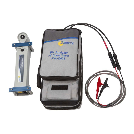
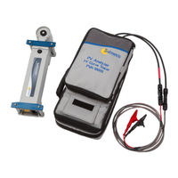
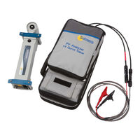
PV Analyzer I-V Curve Tracer with SolSensor
Brand:
Solmetric
| Category:
Measuring Instruments
| Size: 3 MB
Table of Contents
Table of Contents
5
Getting Started
13
Overview
13
Computer Minimum System Requirements
14
Equipment
15
Curve Tracer Equipment (PVA-1500Xx, PVA-1000S, PVA-600 )
15
Solsensor Equipment
15
Specifications
16
PVA-1500Xx I-V Measurement Unit Specifications
16
PVA-1500Xx Test Lead and Clip Specifications
17
PVA-1000S I-V Measurement Unit Specifications
18
Specifications
19
Table 4. Pva-600
19
Solsensor 300 and Solsensor 300V2 Specifications
20
Table 5. Sol Sensor
20
Solsensor (Original) Specifications
22
Table 6. Solsensor Specifications
22
Safety and Regulatory
23
PVA-1500Xx Safety and Regulatory
23
Warnings, Cautions, and Notes
23
Cleaning
24
Declaration of Conformity
24
Instrument Markings
24
PVA-1000S Safety and Regulatory
24
Warnings, Cautions, and Notes
24
Cleaning
25
Declaration of Conformity
25
Instrument Markings
25
Safety and Regulatory
25
Warnings, Cautions, and Notes
25
Cleaning
26
Declaration of Conformity
26
Instrument Markings
26
Solsensor 300 and Solsensor 300V2 Safety and Regulatory
27
Cleaning
27
Declaration of Conformity
27
Instrument Markings
27
Warnings, Cautions, and Notes
27
Solsensor (Original) Safety and Regulatory
28
Cleaning
28
Declaration of Conformity
28
Warnings, Cautions, and Notes
28
Instrument Markings
29
Precautions
30
PVA-1500Xx Precautions
30
Using Test Leads and Clips
30
Pv/Electrical Safety Precautions
31
Using PV Connector Saver Jumpers
31
Battery Precautions
33
Measuring High-Efficiency PV Modules
33
PVA-1000S Precautions
33
Using PV Connector Saver Jumpers
33
Pv/Electrical Safety Precautions
34
Battery Precautions
35
Measuring High-Efficiency PV Modules
35
Precautions
35
Using PV Connector Saver Jumpers
35
Pv/Electrical Safety Precautions
36
Battery Precautions
37
Measuring High-Efficiency PV Modules
37
Solsensor 300Xx, Solsensor 200, and Original Solsensor Precautions
37
Covering the Irradiance Sensor
37
Battery Precautions
38
Cleaning the Irradiance Sensor
38
Installation Procedure
39
I-V Measurement Unit Installation Procedure
39
Figure 2. Welcome Screen
39
Hardware Installation
39
Software Installation
39
Figure 3. Prerequisites Dialog
40
Figure 4. Installation Default Location Dialog
40
Figure 5. Insert Wireless Usb Adapter Dialog
41
Figure 6. Insert Wireless Usb
41
Figure 7. Installation Complete Dialog
42
Figure 8. Launching the Pva
42
Figure 9. Splash Screen
42
Figure 10. the Software User Interface Shared by the
43
Figure 11. Directory Structure of
43
Updating the PV Equipment Databases
43
Solsensor Installation Procedure
44
Charging the Battery
44
Charging the Battery on the PVA-1500Xx I-V Measurement Units
44
Figure 12. Battery Charger Connector on the Figure 13. Charger Connected
44
Charging the Solsensor 300Xx Battery
45
Charging the Battery on the PVA-1000S and PVA-600 + I-V Measurement Unit
45
Charging the Solsensor Battery of the Original Solsensor
46
Figure 14. Battery Charger Connector on the Figure 15. Charger Connected
46
Your Wireless Network
47
Your PVA-1500Xx/Solsensor 300Xx Wireless Network
47
Figure 16. the W I F I Network of the Figure 17. Network Icon
47
Your PVA-1000S/600 /Solsensor Wireless Network
48
Figure 18. Network Diagrams
49
Table 7. Direct and Indirect Wireless Links between
49
Setting up and Using the I-V Measurement Unit and Solsensor
50
System Controls and Settings
50
Operational States of the PVA-1500Xx I-V Measurement Units
50
Operational States of the PVA-1000S & 600
52
I-V Measurement Unit
52
Setting up the I-V Measurement Unit
53
Setting up Solsensor
54
Figure 20. Sols
54
Mounting Sol Sensor to Apv Module Frame
55
Figure 21. Sols
55
Figure 22. Sols
56
Figure 23. Tip of Frame Clamp Properly Seated on Inside Surface of Module Frame
56
Figure 24. Thermocouple Plugged into the Figure 25. Locating the Thermocouple Tip on a Single Free
57
Figure 26. Sol Sensor Pushbutton with
58
Optimizing Wireless Transmission Range
59
Mounting Solsensor on a Tripod
59
Figure 27. Tripod Mounting Setup
60
Connecting to the Solar Pv Equipment
61
Figure 28. Example of I-V M
62
Powering-Up the I-V Measurement Unit
63
Figure 29. Powering - up the
63
I-V Measurements
64
Sweep Disabled
64
Over-Temperature Protection
64
Thermal Capacity of the PVA-1500Xx
65
Operating under High-Temperature Conditions
65
Over-Voltage Warnings
66
PVA-1500Xx Over-Voltage Condition
66
PVA-1000S Over-Voltage Condition
66
Over-Voltage Protection
66
Over-Current Warnings
66
Reverse Polarity Protection
67
Software Overview
69
Using Projects
69
Using the System Tree
70
Main Screen Overview
70
Menu Bar
71
File Menu
71
Browse Project
71
Export Trace for Active Measurement
71
Export Traces for Entire System
71
Figure 31. File Menu
71
Recent Projects
71
Export Meg Test Data
72
Figure 32. the Site Info Screen of the Figure 33. Controls in the Site
72
New Project
72
Figure 34. most Common Settings for a Horizontal Single
73
Figure 35. the Time Zone Control in the Figure 36. the Pv M
73
Figure 37. Selection of the Pv
74
Selecting Your PV Module
74
Creating the System Tree
75
Figure 38. Array Navigator with
75
Figure 39. Finished Array Tree for a Utility
76
Figure 40. the Default System Tree in the Figure 41. Controls for Editing the String Wiring Properties of Your Array Tree
76
Using the Symmetrical Tree Builder
76
Cloning, Modifying, and Reusing a Previous Project
79
Properties Menu
79
Figure 42. Directory Structure Used by the Figure 43. Properties Menu
79
View Menu
80
Show Meg Test Tab
80
Trace View Options
80
Utility Menu
80
Figure 44. Utility Menu
80
Table 10. Utility Menu Description
81
Help Menu
83
Figure 45. Help Menu
83
Table 11. Help Menu Description
83
Using the Tab Screens
84
Traces Tab
84
Figure 46. Traces Tab
84
Table 12. Traces Tab Description
85
Figure 47. Table Tab
89
Table 13. Table Tab Description
89
History Tab
90
Meg Test Tab
91
Figure 48. History Tab
91
Figure 49. Meg Test Tab
91
Description of the Exported I-V Data File
92
Table 14. Meg Test Tab Description
92
Figure 50. Headeri
93
Table 15. Description of Theh
93
Figure 51. the Measurement Vs
94
Figure 52. the Sol Sensorm
94
Figure 53. Modeld
95
Table 16. Description of Thes
95
Table 17. Description of Them
96
Basis of Pv Performance Predictions
97
Solsensor Irradiance Calibration
97
Figure 54. the Voltage , Current
97
Irradiance Measurement
98
Prediction of PV Performance
98
Translation of Measured Values to STC
98
Measurement of I
99
Pva Pc Software Updates
99
PVA-1500V2/V3 and Solsensor 300V2 Firmware Updates
99
Solmetric PVA-1000S User Manual (142 pages)
PV Analyzer I-V Curve Tracer
Brand:
Solmetric
| Category:
Measuring Instruments
| Size: 20 MB
Table of Contents
Table of Contents
5
Getting Started
13
Overview
13
Computer Minimum System Requirements
14
Equipment
14
Curve Tracer Equipment (PVA-1500S, PVA-1000S, PVA-600 )
15
Solsensor Equipment
15
Specifications
16
PVA-1500S Specifications
16
Pva-1500S Electrical and Mechanical Specifications
16
PVA-1000S Specifications
17
Pva-1000S Electrical and Mechanical Specifications
17
Specifications
18
Table 3. Pva-600
18
PVA-600 + Specifications
18
Solsensor 300 Specifications
19
Table 4. Solsensor 300 Specifications
19
Solsensor (Original) Specifications
21
Table 5. Solsensor Specifications
21
Safety and Regulatory
23
PVA-1500S Safety and Regulatory
23
Cleaning
23
Declaration of Conformity
23
Instrument Markings
23
Warnings, Cautions, and Notes
23
PVA-1000S Safety and Regulatory
24
Cleaning
24
Declaration of Conformity
24
Instrument Markings
24
Warnings, Cautions, and Notes
24
Safety and Regulatory
25
Cleaning
25
Declaration of Conformity
25
Instrument Markings
25
PVA-600 + Safety and Regulatory
25
Warnings, Cautions, and Notes
25
Solsensor 300 Safety and Regulatory
26
Cleaning
26
Declaration of Conformity
26
Warnings, Cautions, and Notes
26
Instrument Markings
27
Solsensor (Original) Safety and Regulatory
27
Declaration of Conformity
27
Warnings, Cautions, and Notes
27
Cleaning
28
Instrument Markings
28
Precautions
29
PVA-1500S Precautions
29
Pv/Electrical Safety Precautions
29
Using PV Connector Saver Jumpers
29
Battery Precautions
31
Measuring High-Efficiency PV Modules
31
PVA-1000S Precautions
31
Using PV Connector Saver Jumpers
31
Pv/Electrical Safety Precautions
32
Battery Precautions
33
Measuring High-Efficiency PV Modules
33
Precautions
33
Using PV Connector Saver Jumpers
33
Pv/Electrical Safety Precautions
34
Battery Precautions
35
Measuring High-Efficiency PV Modules
35
Solsensor and Solsensor 300 Precautions
36
Battery Precautions
36
Cleaning the Irradiance Sensor
36
Covering the Irradiance Sensor
36
Installation Procedure
37
I-V Measurement Unit Installation Procedure
37
Figure 1. Welcome Screen
37
Hardware Installation
37
Software Installation
37
Figure 2. Prerequisites Dialog
38
Figure 3. Installation Default Location Dialog
38
Figure 4. Insert Wireless Usb Adapter Dialog
39
Figure 5. Insert Wireless USB Adapter (PVA-600+ and PVA-1000S Only)
39
Figure 6. Installation Complete Dialog
40
Figure 7. Launching the Pva Software
40
Figure 8. Splash Screen
40
Updating the PV Equipment Databases
41
Solsensor Installation Procedure
41
Figure 9. the Software User Interface Shared by the
41
Figure 10. Directory Structure of Pva Software
41
Charging the Battery
42
Charging the Battery on the PVA-1500S I-V Measurement Unit
42
Charging the Solsensor 300 Battery
42
Figure 11. Battery Charger Connector on the I-V Measurement Unit
42
Charging the Battery on the PVA-1000S and PVA-600
43
Figure 12. Charger Connected
43
Figure 13. Battery Charger Connector on the Figure 14. Charger Connected
43
I-V Measurement Unit
43
Charging the Solsensor Battery of the Original Solsensor
44
Your Wireless Network
44
Your PVA-1500S/Solsensor 300 Wireless Network
44
Your PVA-1000S/600 /Solsensor Wireless Network
45
Figure 15. the W I F I Network of the Figure 16. Network Icon
45
Figure 17. Network Diagrams
46
Table 6. Direct and Indirect Wireless Links between PC, PVA, and Solsensor
47
Setting up and Using the I-V Measurement Unit and Solsensor
49
System Controls and Settings
49
Operational States of the PVA-1500S I-V Measurement Unit
50
Table 7. I-V Operational States of the Pva-1500S
50
Table 8. I-V Operational States of the PVA-1000S & 600
51
Setting up the I-V Measurement Unit
52
Setting up Solsensor
52
Mounting Sol Sensor to Apv Module Frame
53
Figure 19. Sols
53
Figure 20. Sol Sensor
54
Figure 21. Sols
54
Figure 22. Tip of Frame Clamp Properly Seated on Inside Surface of Module Frame
55
Figure 23. Thermocouple Plugged into the Figure 24. Locating the Thermocouple Tip on a Single Free
55
Optimizing Wireless Transmission Range
57
Mounting Solsensor on a Tripod
57
Figure 25. Solsensor Pushbutton with
57
Figure 26. Tripod Mounting Setup
58
Connecting to the Solar Pv Equipment
59
Figure 27. Example of I-V M
60
Powering-Up the I-V Measurement Unit
61
Figure 28. Powering - up the I-V M
61
I-V Measurements
62
Sweep Disabled
62
Over-Temperature Protection
62
Thermal Capacity of the PVA-1500S
63
Operating under High-Temperature Conditions
63
Over-Voltage Protection
63
PVA-1500S Over-Voltage Protection
63
PVA-1000S Over-Voltage Protection
64
Over-Voltage Protection
64
Over-Current Protection
64
Reverse Polarity Protection
64
Software Overview
65
Using Projects
65
Using the System Tree
66
Main Screen Overview
66
Menu Bar
67
File Menu
67
Browse Project
67
Export Trace for Active Measurement
67
Export Traces for Entire System
67
Figure 30. File Menu
67
Recent Projects
67
Export Meg Test Data
68
Figure 31. the Site Info Screen of the Figure 32. Roof Azimuth Tool
68
New Project
68
Figure 33. Roof Azimutht
69
Figure 34. Finding the Azimuth
70
Figure 35. Finding Your Site
71
Figure 36. Controls in the Site
71
Figure 37. Settings for a Horizontal Single
72
Figure 38. the Time Zone Control in the Figure 39. the Pv M
72
Figure 40. Selection of the Pv
73
Selecting Your PV Module
73
Creating the System Tree
74
Figure 41. Array Navigator with
74
Figure 42. Finished Array Tree for a Utility
74
Figure 43. the Default System Tree in the Figure 44. Controls for Editing the String Wiring Properties of Your Array Tree
75
Using the Symmetrical Tree Builder
75
Cloning, Modifying, and Reusing a Previous Project
77
Properties Menu
77
Figure 45. Directory Structure Used by the Figure 46. Properties Menu
77
View Menu
78
Show Meg Test Tab
78
Trace View Options
78
Utility Menu
78
Figure 47. Utility Menu
78
Table 9. Utility Menu Description
79
Help Menu
81
Figure 48. Help Menu
81
Table 10. Help Menu Description
81
Using the Tab Screens
82
Traces Tab
82
Figure 49. Traces Tab
82
Table 11. Traces Tab Description
83
Table Tab
86
Figure 50. Table Tab
87
Table 12. Table Tab Description
87
History Tab
88
Figure 51. History Tab
88
Meg Test Tab
89
Figure 52. Meg Test Tab
89
Table 13. Meg Test Tab Description
89
Description of the Exported I-V Data File
90
Figure 53. Headeri
91
Figure 54. the Measurement Vs
91
Table 14. Description of the Header Information Section of the Exported Csv File
91
Figure 55. the Sol Sensorm
92
Table 15. Description of the Solsensor Measurements Section of the Exported Csv File
92
Figure 56. Model Details Section of the Exported Csv File
93
Table 16. Description of the Model Details Section of the Exported Csv File
93
Figure 57. the Voltage, Current, and Power Data from the I-V Measurement
94
Basis of Pv Performance Predictions
95
Solsensor Irradiance Calibration
95
Irradiance Measurement
95
Prediction of PV Performance
96
Translation of Measured Values to STC
96
Measurement of I
96
Advertisement
Solmetric PVA-1000S User Manual (150 pages)
PV Analyzer I-V Curve Tracer
Brand:
Solmetric
| Category:
Measuring Instruments
| Size: 4 MB
Table of Contents
Table of Contents
5
Getting Started
13
Overview
13
Computer Minimum System Requirements
14
Equipment
15
Curve Tracer Equipment (PVA-1500Xx, PVA-1000S, PVA-600 )
15
Solsensor Equipment
15
Specifications
16
PVA-1500Xx I-V Measurement Unit Specifications
16
PVA-1500Xx Test Lead and Clip Specifications
18
PVA-1000S I-V Measurement Unit Specifications
18
Specifications
20
Solsensor 200/300/300V2 Specifications
21
Safety and Regulatory
22
PVA-1500Xx Safety and Regulatory
22
Warnings, Cautions, and Notes
22
Declaration of Conformity
23
Cleaning
23
Instrument Markings
23
PVA-1000S Safety and Regulatory
23
Warnings, Cautions, and Notes
23
Declaration of Conformity
24
Cleaning
24
Instrument Markings
24
Safety and Regulatory
24
Warnings, Cautions, and Notes
25
Declaration of Conformity
25
Cleaning
25
Instrument Markings
25
Solsensor 300 and Solsensor 300V2 Safety and Regulatory
27
Warnings, Cautions, and Notes
27
Declaration of Conformity
27
Cleaning
27
Instrument Markings
27
Solsensor (Original) Safety and Regulatory
28
Warnings, Cautions, and Notes
28
Declaration of Conformity
28
Cleaning
28
Instrument Markings
29
Precautions
30
PVA-1500Xx Precautions
30
Using Test Leads and Clips
30
Using PV Connector Saver Jumpers
31
Pv/Electrical Safety Precautions
31
Battery Precautions
33
Measuring High-Efficiency PV Modules
33
PVA-1000S Precautions
33
Using PV Connector Saver Jumpers
33
Pv/Electrical Safety Precautions
34
Battery Precautions
35
Measuring High-Efficiency PV Modules
35
Precautions
35
Using PV Connector Saver Jumpers
35
Pv/Electrical Safety Precautions
36
Battery Precautions
37
Measuring High-Efficiency PV Modules
37
Solsensor 300Xx, Solsensor 200, and Original Solsensor Precautions
37
Covering the Irradiance Sensor
37
Cleaning the Irradiance Sensor
38
Battery Precautions
38
Installation Procedure
39
I-V Measurement Unit Installation Procedure
39
Hardware Installation
39
Software Installation
39
Figure 2. Welcome Screen
39
Figure 3. Prerequisites Dialog
40
Figure 4. Installation Default Location Dialog
40
Figure 5. Insert Wireless Usb Adapter Dialog
41
Figure 6. Insert Wireless Usb
41
Figure 7. Installation Complete Dialog
42
Figure 8. Launching the Pva
42
Figure 9. Splash Screen
42
Updating the PV Equipment Databases
43
Figure 10. the Software User Interface Shared by the
43
Figure 11. Directory Structure of
43
Solsensor Installation Procedure
44
Charging the Battery
44
Charging the Battery on the PVA-1500Xx I-V Measurement Units
44
Figure 12. Battery Charger Connector on the Figure 13. Charger Connected
44
Charging the Solsensor 300Xx Battery
45
Charging the Battery on the PVA-1000S and PVA-600 + I-V Measurement Unit
45
Charging the Solsensor Battery of the Original Solsensor
46
Figure 14. Battery Charger Connector on the Figure 15. Charger Connected
46
Your Wireless Network
47
Your PVA-1500Xx/Solsensor 300Xx Wireless Network
47
Figure 16. the W I F I Network of the Figure 17. Network Icon
47
Your PVA-1000S/600 /Solsensor Wireless Network
48
Figure 18. Network Diagrams
49
Setting up and Using the I-V Measurement Unit and Solsensor
50
System Controls and Settings
50
Operational States of the PVA-1500Xx I-V Measurement Units
50
Operational States of the PVA-1000S & 600
52
I-V Measurement Unit
52
Setting up the I-V Measurement Unit
53
Setting up Solsensor
54
Figure 20. Sols
54
Mounting Sol Sensor to Apv Module Frame
55
Figure 21. Sols
55
Figure 22. Sols
56
Figure 23. Tip of Frame Clamp Properly Seated on Inside Surface of Module Frame
56
Figure 24. Thermocouple Plugged into the Figure 25. Locating the Thermocouple Tip on a Single Free
57
Figure 26. Sol Sensor Pushbutton with
58
Optimizing Wireless Transmission Range
59
Mounting Solsensor on a Tripod
59
Figure 27. Tripod Mounting Setup
60
Connecting to the Solar Pv Equipment
61
Figure 28. Example of I-V M
62
Powering-Up the I-V Measurement Unit
63
Figure 29. Powering - up the
63
I-V Measurements
64
Sweep Disabled
64
Over-Temperature Protection
64
Sweep-To-Sweep Delay and Thermal Capacity of the PVA-1500Xx
65
Operating under High-Temperature Conditions
66
Over-Voltage Warnings
67
PVA-1500Xx Over-Voltage Condition
67
PVA-1000S Over-Voltage Condition
67
Over-Current Warnings
67
Over-Voltage Protection
67
Reverse Polarity Protection
68
Software Overview
69
Using Projects
69
Using the System Tree
70
Main Screen Overview
70
Menu Bar
71
File Menu
71
Browse Project
71
Recent Projects
71
Export Trace for Active Measurement
71
Export Traces for Entire System
71
Figure 31. File Menu
71
Export Meg Test Data
72
New Project
72
Figure 32. the Site Info Screen of the Figure 33. Controls in the Site
72
Figure 34. most Common Settings for a Horizontal Single
73
Figure 35. the Time Zone Control in the Figure 36. the Pv M
73
Selecting Your PV Module
74
Figure 37. Selection of the Pv
74
Creating the System Tree
75
Figure 38. Array Navigator with
75
Using the Symmetrical Tree Builder
76
Figure 39. Finished Array Tree for a Utility
76
Figure 40. the Default System Tree in the Figure 41. Controls for Editing the String Wiring Properties of Your Array Tree
76
Cloning, Modifying, and Reusing a Previous Project
79
Properties Menu
79
Figure 42. Directory Structure Used by the Figure 43. Properties Menu
79
View Menu
80
Trace View Options
80
Show Meg Test Tab
80
Utility Menu
80
Figure 44. Utility Menu
80
Help Menu
83
Figure 45. Help Menu
83
Using the Tab Screens
84
Traces Tab
84
Figure 46. Traces Tab
84
Figure 47. Table Tab
89
History Tab
90
Meg Test Tab
91
Figure 48. History Tab
91
Description of the Exported I-V Data File
92
Basis of Pv Performance Predictions
97
Solsensor Irradiance Calibration
97
Irradiance Measurement
98
Prediction of PV Performance
98
Translation of Measured Values to STC
98
Measurement of I
99
Pva Pc Software Updates
99
Pva-1500V2/V3/V4/Tand Sol Sensor 300V2 Firmware Updates
99
Solmetric PVA-1000S User Manual (129 pages)
PV Analyzer and SolSensor
Brand:
Solmetric
| Category:
Measuring Instruments
| Size: 7 MB
Table of Contents
Table of Contents
5
Getting Started
11
Overview
11
Computer Minimum System Requirements
12
Equipment
12
PVA-1000S Equipment
12
Nit
12
Solsensor Equipment
13
Specifications
14
PVA-1000S Specifications
14
Pva-1000S
14
Solsensor Specifications
15
Table 2. Solsensor Irradiance Specifications
15
Safety and Regulatory
17
Cleaning
17
Declaration of Conformity
17
PVA-1000S Safety and Regulatory
17
Warnings, Cautions, and Notes
17
Cleaning
18
Declaration of Conformity
18
Instrument Markings
18
Solsensor Safety and Regulatory
18
Warnings, Cautions, and Notes
18
Instrument Markings
19
Precautions
20
Pv/Electrical Safety Precautions
20
PVA-1000S Precautions
20
Using PV Connector Saver Jumpers
20
Battery Precautions
21
Battery Precautions
22
Cleaning the Irradiance Sensor
22
Covering the Irradiance Sensor
22
Measuring High-Efficiency PV Modules
22
Solsensor Precautions
22
Installation Procedure
23
Figure 1. Welcome Screen
23
Hardware Installation
23
PVA-1000S Installation Procedure
23
Software Installation
23
Figure 2. Prerequisites Dialog
24
Figure 3. Installation Default Location Dialog
24
Figure 4. Insert Wireless Usb
25
Figure 5. Insert Wireless Usb
25
Figure 6. Installation Complete Dialog
25
Figure 7. Launching the Figure 8. Splash Screen
26
Drivers for Solsensor
27
Figure 10. Directory Structure of
27
Solsensor Installation Procedure
27
Special XP Operating System Instructions
27
Updating the PV Equipment Databases
27
Charging the Battery
28
Changing the Battery on the PVA-1000S
28
Changing the Solsensor Battery
28
Figure 11. Battery Charger Connector on the Figure 12. Charger Connected
28
Your Wireless Network
29
Figure 13. Network Icon
30
Figure 14. Network Diagrams
30
Table 3. Direct and Indirect Wireless Links between
31
Setting up and Using the Pva-1000S and Solsensor
33
System Controls and Settings
33
PVA-1000S Operational States
33
Figure 16. Sols
35
S Etting U P the Pva-1000S
35
Figure 17. Sol Sensor
36
Figure 18. Sols
37
Figure 19. Tip of Frame Clamp Properly Seated on Inside Surface of Module Frame
38
Figure 20. Thermocouple Plugged into the Figure 21. Locating the Thermocouple Tip on a Single Free
38
Figure 22. Pushbutton with
40
Figure 23. Tripod Mounting Setup
42
Figure 24. Example of Pva-1000S
44
Figure 25. Powering - up the I-V U
45
P Rotection
46
Operating under High-Temperature Conditions
47
Rotection
48
Software Overview
49
Figure 27. File Menu
51
Figure 28. the Site Info Screen of the Figure 29. Roof Measurement
52
Figure 30. Roof Measurement
53
Figure 31. Finding the Azimuth
53
Figure 32. the Arrayn
54
Figure 33. Change Module Screen
54
Selecting Your PV Module
54
Table 5. Change Module Screen
55
Description
55
Creating the System Tree
56
Figure 34. Array Navigators
56
Table 6. Array Navigator Screen Description
57
Figure 35. Properties Menu
60
Figure 36. Site Informations
61
Figure 37. Array Navigators
61
Site Info
61
Figure 38. Utility Menu
62
Table 7. Utility Menu Description
62
Figure 39. Help Menu
64
Table 8. Help Menu Description
64
Figure 40. Traces Tab
65
Table 9. Traces Tab Description
66
Figure 41. Table Tab
69
History Tab
70
Table 10. Table Tab Description
70
Figure 42. History Tab
71
Figure 43. Meg Test Tab
71
Table 11. Meg Test Tab Description
72
Figure 44. Headeri
73
Table 12. Description of Theh
73
Figure 45. the Measurement Vs
74
Figure 46. the Sol Sensorm
74
Table 13. Description of Thes
74
Figure 47. Modeld
75
Table 14. Description of Them
75
Figure 48. the Voltage , Current
76
Solsensor Irradiance Calibration
77
PVA Prediction of Electrical Output
78
Making Measurements
79
Introduction
79
Creating a New Project
79
Start the PVA-1000S Software
80
Select New Project
80
Figure 49. Traces Screen
80
Enter the Site Information
81
Figure 50. Site Information Screen of the Figure 51. Roof Measurement
81
Figure 52. Measuring Your Roof Orientation
82
Select PV Module
83
Figure 53. Second Screen of the New Project Wizard
83
Figure 54. Change Module Screen
83
Create the System Tree
84
Figure 55. the Second Screen of the Figure 56. Autofill Tree Screen
84
Add a New Inverter
85
Figure 57. Populated Arrayn
85
Figure 58. Add Inverter Screen
85
Add a New Combiner
86
Add a New String
86
Figure 59. New Combiner Screen
86
Edit Wire Properties
87
Create a Custom PV Model
87
Figure 60. Add String Screen
87
Creating a New Project that Is Similar to an Existing Project
88
Making Measurements
88
Figure 61. Directory Structure of
88
Using the History Tab
90
Saving a Screen Image
90
Exporting Measurement Data
90
Solmetric PVA-1000S Quick Reference Card (2 pages)
Brand:
Solmetric
| Category:
Test Equipment
| Size: 0 MB
Table of Contents
Current Range
1
Voltage Range
1
Operating Temperature
1
Battery Run Time
1
I-V Unit LED States
1
Measurement Example
1
Troubleshooting PVA & Solsensor Operation
2
Common Issues and Solutions
2
Software Updates
2
Technical Support
2
Solmetric PVA-1000S Quick Reference Card (2 pages)
Brand:
Solmetric
| Category:
Measuring Instruments
| Size: 0 MB
Table of Contents
I-V Measurement Unit Specifications
1
Test Lead and Clip Specifications
1
I-V Unit LED
1
Measurement Example - Testing Strings at a Fused Combiner Box
2
Troubleshooting I-V Unit & Solsensor Operation
2
Software Updates
2
Technical Support
2
Advertisement
Related Products
Solmetric PVA-1500S
Solmetric PVA-1500V2
Solmetric PVA-1500V3
Solmetric PVA-1500V4
Solmetric PVA-1500T
Solmetric PV ANALYZER PVA-1500 Series
Solmetric PV ANALYZER PVA-1500HE
Solmetric PVA-600+
Solmetric PVA-600
Solmetric SunEye 210
Solmetric Categories
Measuring Instruments
Test Equipment
GPS
Lifting Systems
More Solmetric Manuals
Login
Sign In
OR
Sign in with Facebook
Sign in with Google
Upload manual
Upload from disk
Upload from URL