Sign In
Upload
Manuals
Brands
Solmetric Manuals
Measuring Instruments
PVA-600+
Solmetric PVA-600+ Manuals
Manuals and User Guides for Solmetric PVA-600+. We have
4
Solmetric PVA-600+ manuals available for free PDF download: User Manual, Quick Reference Card
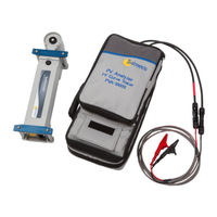
Solmetric PVA-600+ User Manual (152 pages)
PV Analyzer I-V Curve Tracer with SolSensor
Brand:
Solmetric
| Category:
Measuring Instruments
| Size: 3 MB
Table of Contents
Table of Contents
5
Getting Started
13
Overview
13
Computer Minimum System Requirements
14
Equipment
15
Curve Tracer Equipment (PVA-1500Xx, PVA-1000S, PVA-600 )
15
Solsensor Equipment
15
Specifications
16
PVA-1500Xx I-V Measurement Unit Specifications
16
PVA-1500Xx Test Lead and Clip Specifications
17
PVA-1000S I-V Measurement Unit Specifications
18
Specifications
19
Table 4. Pva-600
19
Solsensor 300 and Solsensor 300V2 Specifications
20
Table 5. Sol Sensor
20
Solsensor (Original) Specifications
22
Table 6. Solsensor Specifications
22
Safety and Regulatory
23
PVA-1500Xx Safety and Regulatory
23
Warnings, Cautions, and Notes
23
Cleaning
24
Declaration of Conformity
24
Instrument Markings
24
PVA-1000S Safety and Regulatory
24
Warnings, Cautions, and Notes
24
Cleaning
25
Declaration of Conformity
25
Instrument Markings
25
Safety and Regulatory
25
Warnings, Cautions, and Notes
25
Cleaning
26
Declaration of Conformity
26
Instrument Markings
26
Solsensor 300 and Solsensor 300V2 Safety and Regulatory
27
Cleaning
27
Declaration of Conformity
27
Instrument Markings
27
Warnings, Cautions, and Notes
27
Solsensor (Original) Safety and Regulatory
28
Cleaning
28
Declaration of Conformity
28
Warnings, Cautions, and Notes
28
Instrument Markings
29
Precautions
30
PVA-1500Xx Precautions
30
Using Test Leads and Clips
30
Pv/Electrical Safety Precautions
31
Using PV Connector Saver Jumpers
31
Battery Precautions
33
Measuring High-Efficiency PV Modules
33
PVA-1000S Precautions
33
Using PV Connector Saver Jumpers
33
Pv/Electrical Safety Precautions
34
Battery Precautions
35
Measuring High-Efficiency PV Modules
35
Precautions
35
Using PV Connector Saver Jumpers
35
Pv/Electrical Safety Precautions
36
Battery Precautions
37
Measuring High-Efficiency PV Modules
37
Solsensor 300Xx, Solsensor 200, and Original Solsensor Precautions
37
Covering the Irradiance Sensor
37
Battery Precautions
38
Cleaning the Irradiance Sensor
38
Installation Procedure
39
I-V Measurement Unit Installation Procedure
39
Figure 2. Welcome Screen
39
Hardware Installation
39
Software Installation
39
Figure 3. Prerequisites Dialog
40
Figure 4. Installation Default Location Dialog
40
Figure 5. Insert Wireless Usb Adapter Dialog
41
Figure 6. Insert Wireless Usb
41
Figure 7. Installation Complete Dialog
42
Figure 8. Launching the Pva
42
Figure 9. Splash Screen
42
Figure 10. the Software User Interface Shared by the
43
Figure 11. Directory Structure of
43
Updating the PV Equipment Databases
43
Solsensor Installation Procedure
44
Charging the Battery
44
Charging the Battery on the PVA-1500Xx I-V Measurement Units
44
Figure 12. Battery Charger Connector on the Figure 13. Charger Connected
44
Charging the Solsensor 300Xx Battery
45
Charging the Battery on the PVA-1000S and PVA-600 + I-V Measurement Unit
45
Charging the Solsensor Battery of the Original Solsensor
46
Figure 14. Battery Charger Connector on the Figure 15. Charger Connected
46
Your Wireless Network
47
Your PVA-1500Xx/Solsensor 300Xx Wireless Network
47
Figure 16. the W I F I Network of the Figure 17. Network Icon
47
Your PVA-1000S/600 /Solsensor Wireless Network
48
Figure 18. Network Diagrams
49
Table 7. Direct and Indirect Wireless Links between
49
Setting up and Using the I-V Measurement Unit and Solsensor
50
System Controls and Settings
50
Operational States of the PVA-1500Xx I-V Measurement Units
50
Operational States of the PVA-1000S & 600
52
I-V Measurement Unit
52
Setting up the I-V Measurement Unit
53
Setting up Solsensor
54
Figure 20. Sols
54
Mounting Sol Sensor to Apv Module Frame
55
Figure 21. Sols
55
Figure 22. Sols
56
Figure 23. Tip of Frame Clamp Properly Seated on Inside Surface of Module Frame
56
Figure 24. Thermocouple Plugged into the Figure 25. Locating the Thermocouple Tip on a Single Free
57
Figure 26. Sol Sensor Pushbutton with
58
Optimizing Wireless Transmission Range
59
Mounting Solsensor on a Tripod
59
Figure 27. Tripod Mounting Setup
60
Connecting to the Solar Pv Equipment
61
Figure 28. Example of I-V M
62
Powering-Up the I-V Measurement Unit
63
Figure 29. Powering - up the
63
I-V Measurements
64
Sweep Disabled
64
Over-Temperature Protection
64
Thermal Capacity of the PVA-1500Xx
65
Operating under High-Temperature Conditions
65
Over-Voltage Warnings
66
PVA-1500Xx Over-Voltage Condition
66
PVA-1000S Over-Voltage Condition
66
Over-Voltage Protection
66
Over-Current Warnings
66
Reverse Polarity Protection
67
Software Overview
69
Using Projects
69
Using the System Tree
70
Main Screen Overview
70
Menu Bar
71
File Menu
71
Browse Project
71
Export Trace for Active Measurement
71
Export Traces for Entire System
71
Figure 31. File Menu
71
Recent Projects
71
Export Meg Test Data
72
Figure 32. the Site Info Screen of the Figure 33. Controls in the Site
72
New Project
72
Figure 34. most Common Settings for a Horizontal Single
73
Figure 35. the Time Zone Control in the Figure 36. the Pv M
73
Figure 37. Selection of the Pv
74
Selecting Your PV Module
74
Creating the System Tree
75
Figure 38. Array Navigator with
75
Figure 39. Finished Array Tree for a Utility
76
Figure 40. the Default System Tree in the Figure 41. Controls for Editing the String Wiring Properties of Your Array Tree
76
Using the Symmetrical Tree Builder
76
Cloning, Modifying, and Reusing a Previous Project
79
Properties Menu
79
Figure 42. Directory Structure Used by the Figure 43. Properties Menu
79
View Menu
80
Show Meg Test Tab
80
Trace View Options
80
Utility Menu
80
Figure 44. Utility Menu
80
Table 10. Utility Menu Description
81
Help Menu
83
Figure 45. Help Menu
83
Table 11. Help Menu Description
83
Using the Tab Screens
84
Traces Tab
84
Figure 46. Traces Tab
84
Table 12. Traces Tab Description
85
Figure 47. Table Tab
89
Table 13. Table Tab Description
89
History Tab
90
Meg Test Tab
91
Figure 48. History Tab
91
Figure 49. Meg Test Tab
91
Description of the Exported I-V Data File
92
Table 14. Meg Test Tab Description
92
Figure 50. Headeri
93
Table 15. Description of Theh
93
Figure 51. the Measurement Vs
94
Figure 52. the Sol Sensorm
94
Figure 53. Modeld
95
Table 16. Description of Thes
95
Table 17. Description of Them
96
Basis of Pv Performance Predictions
97
Solsensor Irradiance Calibration
97
Figure 54. the Voltage , Current
97
Irradiance Measurement
98
Prediction of PV Performance
98
Translation of Measured Values to STC
98
Measurement of I
99
Pva Pc Software Updates
99
PVA-1500V2/V3 and Solsensor 300V2 Firmware Updates
99
Making Measurements
101
Introduction
101
Before You Go to the Field to Make Measurements
101
Charge the Equipment
101
Check that You Are Using the Latest PVA Software
101
Create a Project in the PVA Software
101
Make Sure You Have All Your Equipment
102
Assure Adequate Irradiance for Your Measurements
102
Making Measurements in the Field
102
Measure the Open Circuit Voltage Voc
102
Place the I-V Unit Near the PV Circuits to be Measured
103
Connect the Test Leads to the PVA
103
Launch the PVA Software
103
Load Your Project
103
Insert the Wireless USB Adapter (PVA-1000S and PVA-600+)
103
Mount Solsensor
104
Attach Solsensor Thermocouple
104
Turn on the I-V Measurement Unit, and Connect Wirelessly to Your PC
104
Turn on Solsensor
105
Prepare the PV Source Circuits for Measurement
105
Are You Measuring Strings in Parallel
105
Are You Measuring High-Efficiency Modules
105
Connect the Test Leads to the PV Equipment
106
Select the First PV Circuit to be Measured
106
Make Your First Measurement
106
Figure 55. Results of an I-V
106
Select the Next PV Circuit and Take Another Measurement
107
View the Consistency of Your Data before Moving on
107
From Time to Time, Back up Your Data
108
Troubleshooting Pva Operation
109
Troubleshooting Using Status Messages
109
Figure 56. Status Indicator
109
Troubleshooting by Symptom
112
Measuring Irradiance, Temperature, and Tilt
117
Introduction
117
Table 18. Sensor Choices
118
Measuring Irradiance with Solsensor
119
Solsensor Irradiance Sensor
119
Preliminary Irradiance
119
Solsensor Precautions
119
Cleaning the Irradiance Sensor
119
Protecting the Irradiance Sensor Element
119
Orienting and Mounting the Irradiance Sensor
120
Albedo Effects
120
Diffuse Light
120
Determining Irradiance from the Measured I-V Curve
121
Entering Irradiance Manually
122
Measuring Pv Module Backside Temperature with a Thermocouple
122
Selecting a Thermocouple Wire Gauge
123
Selecting a Thermocouple Tip
123
Selecting a Tape for Thermocouple Attachment
123
Attaching the Thermocouple to the Module Backside
124
Choosing a Location to Mount the Thermocouple on the Module or Array
124
Measuring Pv Module Temperature with an Infrared Thermometer
125
Determining Cell Temperature from the Measured I-V Curve
126
Using Smarttemp to Measure Cell Temperature
127
Interpreting Measured I-V Curves
129
Introduction
129
Inputs to the Pv Model
129
I-V Curve Terminology
130
Performance Factor
130
Fill Factor
130
The Shape of a Normal I-V Curve
131
Figure 57. Definition of Thef
131
Figure 58. Anormal I-V
131
Interpreting I-V Curves
132
Figure 59. Deviations in the Shape of the
134
Notches or Steps
135
Figure 60. the Effect of Partial Shading on a String
135
Figure 61. the Shading Impact of Placing a Business Card on a Single Cell in a String of Fifteen
136
Figure 62. the Effect of Intentionally Shading Entire Modules in Different Combinations
136
Array Is Partially Shaded, or Non-Uniform Soiling or Debris Is Present
137
Cell String Conductor Is Short Circuited
138
PV Cells Are Damaged
138
Low Current
138
Uniform Soiling
139
Strip Shade
139
Dirt Dam
139
Module Degradation
140
Incorrect PV Module Is Selected for the PV Model
140
Number of PV Strings in Parallel Is Not Entered Correctly in the Model
140
Irradiance Changed between Irradiance and I-V Measurements
140
Irradiance Sensor Is Not Oriented in the Plane of Array
140
Albedo Effects (Reflection) Contribute Additional Irradiance
140
Irradiance Is too Low, or the Sun Is too Close to the Horizon
141
Manual Irradiance Sensor Is Not Accurate
141
Low Voltage
141
Figure 63. Measurement with Less Steep than Predicted Slope in the Vertical Leg of the Figure 64. I-Vcurve Measurement Showing Rounder Knee than Predicted by the
141
One or more Bypass Diodes Are Conducting or Shorted
142
One or more Cells or Modules Are Completely Shaded
142
PV Cell Temperature Is Hotter than the Measured Temperature
142
Rounder Knee
143
Steeper Slope in Horizontal Leg
144
Shunt Paths Exist in PV Cells or Modules
144
Figure 65. a N I-V
144
Module I Sc Mismatch
145
Tapered Shade or Dirt Dam
145
Less Steep Slope in Vertical Leg
146
PV Wiring Has Excess Resistance or Is Insufficiently Sized
146
Figure 66. Measurement with Less Steep Slope in the Vertical Leg of the
146
Electrical Interconnections in the Array Are Resistive
147
Series Resistance of PV Modules Has Increased
147
Translation of I-V Data to Standard Test Conditions
149
Parameter Definitions
149
Translation Equations
150
Advertisement
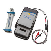
Solmetric PVA-600+ User Manual (142 pages)
PV Analyzer I-V Curve Tracer
Brand:
Solmetric
| Category:
Measuring Instruments
| Size: 20 MB
Table of Contents
Table of Contents
5
Getting Started
13
Overview
13
Computer Minimum System Requirements
14
Equipment
14
Curve Tracer Equipment (PVA-1500S, PVA-1000S, PVA-600 )
15
Solsensor Equipment
15
Specifications
16
PVA-1500S Specifications
16
Pva-1500S Electrical and Mechanical Specifications
16
PVA-1000S Specifications
17
Pva-1000S Electrical and Mechanical Specifications
17
Specifications
18
Table 3. Pva-600
18
PVA-600 + Specifications
18
Solsensor 300 Specifications
19
Table 4. Solsensor 300 Specifications
19
Solsensor (Original) Specifications
21
Table 5. Solsensor Specifications
21
Safety and Regulatory
23
PVA-1500S Safety and Regulatory
23
Cleaning
23
Declaration of Conformity
23
Instrument Markings
23
Warnings, Cautions, and Notes
23
PVA-1000S Safety and Regulatory
24
Cleaning
24
Declaration of Conformity
24
Instrument Markings
24
Warnings, Cautions, and Notes
24
Safety and Regulatory
25
Cleaning
25
Declaration of Conformity
25
Instrument Markings
25
PVA-600 + Safety and Regulatory
25
Warnings, Cautions, and Notes
25
Solsensor 300 Safety and Regulatory
26
Cleaning
26
Declaration of Conformity
26
Warnings, Cautions, and Notes
26
Instrument Markings
27
Solsensor (Original) Safety and Regulatory
27
Declaration of Conformity
27
Warnings, Cautions, and Notes
27
Cleaning
28
Instrument Markings
28
Precautions
29
PVA-1500S Precautions
29
Pv/Electrical Safety Precautions
29
Using PV Connector Saver Jumpers
29
Battery Precautions
31
Measuring High-Efficiency PV Modules
31
PVA-1000S Precautions
31
Using PV Connector Saver Jumpers
31
Pv/Electrical Safety Precautions
32
Battery Precautions
33
Measuring High-Efficiency PV Modules
33
Precautions
33
Using PV Connector Saver Jumpers
33
Pv/Electrical Safety Precautions
34
Battery Precautions
35
Measuring High-Efficiency PV Modules
35
Solsensor and Solsensor 300 Precautions
36
Battery Precautions
36
Cleaning the Irradiance Sensor
36
Covering the Irradiance Sensor
36
Installation Procedure
37
I-V Measurement Unit Installation Procedure
37
Figure 1. Welcome Screen
37
Hardware Installation
37
Software Installation
37
Figure 2. Prerequisites Dialog
38
Figure 3. Installation Default Location Dialog
38
Figure 4. Insert Wireless Usb Adapter Dialog
39
Figure 5. Insert Wireless USB Adapter (PVA-600+ and PVA-1000S Only)
39
Figure 6. Installation Complete Dialog
40
Figure 7. Launching the Pva Software
40
Figure 8. Splash Screen
40
Updating the PV Equipment Databases
41
Solsensor Installation Procedure
41
Figure 9. the Software User Interface Shared by the
41
Figure 10. Directory Structure of Pva Software
41
Charging the Battery
42
Charging the Battery on the PVA-1500S I-V Measurement Unit
42
Charging the Solsensor 300 Battery
42
Figure 11. Battery Charger Connector on the I-V Measurement Unit
42
Charging the Battery on the PVA-1000S and PVA-600
43
Figure 12. Charger Connected
43
Figure 13. Battery Charger Connector on the Figure 14. Charger Connected
43
I-V Measurement Unit
43
Charging the Solsensor Battery of the Original Solsensor
44
Your Wireless Network
44
Your PVA-1500S/Solsensor 300 Wireless Network
44
Your PVA-1000S/600 /Solsensor Wireless Network
45
Figure 15. the W I F I Network of the Figure 16. Network Icon
45
Figure 17. Network Diagrams
46
Table 6. Direct and Indirect Wireless Links between PC, PVA, and Solsensor
47
Setting up and Using the I-V Measurement Unit and Solsensor
49
System Controls and Settings
49
Operational States of the PVA-1500S I-V Measurement Unit
50
Table 7. I-V Operational States of the Pva-1500S
50
Table 8. I-V Operational States of the PVA-1000S & 600
51
Setting up the I-V Measurement Unit
52
Setting up Solsensor
52
Mounting Sol Sensor to Apv Module Frame
53
Figure 19. Sols
53
Figure 20. Sol Sensor
54
Figure 21. Sols
54
Figure 22. Tip of Frame Clamp Properly Seated on Inside Surface of Module Frame
55
Figure 23. Thermocouple Plugged into the Figure 24. Locating the Thermocouple Tip on a Single Free
55
Optimizing Wireless Transmission Range
57
Mounting Solsensor on a Tripod
57
Figure 25. Solsensor Pushbutton with
57
Figure 26. Tripod Mounting Setup
58
Connecting to the Solar Pv Equipment
59
Figure 27. Example of I-V M
60
Powering-Up the I-V Measurement Unit
61
Figure 28. Powering - up the I-V M
61
I-V Measurements
62
Sweep Disabled
62
Over-Temperature Protection
62
Thermal Capacity of the PVA-1500S
63
Operating under High-Temperature Conditions
63
Over-Voltage Protection
63
PVA-1500S Over-Voltage Protection
63
PVA-1000S Over-Voltage Protection
64
Over-Voltage Protection
64
Over-Current Protection
64
Reverse Polarity Protection
64
Software Overview
65
Using Projects
65
Using the System Tree
66
Main Screen Overview
66
Menu Bar
67
File Menu
67
Browse Project
67
Export Trace for Active Measurement
67
Export Traces for Entire System
67
Figure 30. File Menu
67
Recent Projects
67
Export Meg Test Data
68
Figure 31. the Site Info Screen of the Figure 32. Roof Azimuth Tool
68
New Project
68
Figure 33. Roof Azimutht
69
Figure 34. Finding the Azimuth
70
Figure 35. Finding Your Site
71
Figure 36. Controls in the Site
71
Figure 37. Settings for a Horizontal Single
72
Figure 38. the Time Zone Control in the Figure 39. the Pv M
72
Figure 40. Selection of the Pv
73
Selecting Your PV Module
73
Creating the System Tree
74
Figure 41. Array Navigator with
74
Figure 42. Finished Array Tree for a Utility
74
Figure 43. the Default System Tree in the Figure 44. Controls for Editing the String Wiring Properties of Your Array Tree
75
Using the Symmetrical Tree Builder
75
Cloning, Modifying, and Reusing a Previous Project
77
Properties Menu
77
Figure 45. Directory Structure Used by the Figure 46. Properties Menu
77
View Menu
78
Show Meg Test Tab
78
Trace View Options
78
Utility Menu
78
Figure 47. Utility Menu
78
Table 9. Utility Menu Description
79
Help Menu
81
Figure 48. Help Menu
81
Table 10. Help Menu Description
81
Using the Tab Screens
82
Traces Tab
82
Figure 49. Traces Tab
82
Table 11. Traces Tab Description
83
Table Tab
86
Figure 50. Table Tab
87
Table 12. Table Tab Description
87
History Tab
88
Figure 51. History Tab
88
Meg Test Tab
89
Figure 52. Meg Test Tab
89
Table 13. Meg Test Tab Description
89
Description of the Exported I-V Data File
90
Figure 53. Headeri
91
Figure 54. the Measurement Vs
91
Table 14. Description of the Header Information Section of the Exported Csv File
91
Figure 55. the Sol Sensorm
92
Table 15. Description of the Solsensor Measurements Section of the Exported Csv File
92
Figure 56. Model Details Section of the Exported Csv File
93
Table 16. Description of the Model Details Section of the Exported Csv File
93
Figure 57. the Voltage, Current, and Power Data from the I-V Measurement
94
Basis of Pv Performance Predictions
95
Solsensor Irradiance Calibration
95
Irradiance Measurement
95
Prediction of PV Performance
96
Translation of Measured Values to STC
96
Measurement of I
96
Making Measurements
97
Introduction
97
Before You Go to the Field to Make Measurements
97
Charge the Equipment
97
Check that You Are Using the Latest PVA Software
97
Create a Project in the PVA Software
97
Make Sure You Have All Your Equipment
98
Assure Adequate Irradiance for Your Measurements
98
Making Measurements in the Field
98
Place the I-V Unit Near the PV Circuits to be Measured
98
Connect the Test Leads to the PVA
98
Launch the PVA Software
99
Load Your Project
99
Insert the Wireless USB Adapter (PVA-1000S and PVA-600+)
99
Mount Solsensor
99
Attach Solsensor's Thermocouple
99
Turn on the I-V Measurement Unit, and Connect Wirelessly to Your PC
100
Turn on Solsensor
100
Prepare the PV Source Circuits for Measurement
100
Connect the Test Leads to the PV Equipment
100
Select the First PV Circuit to be Measured
101
Make Your First Measurement
101
Figure 58. Results of an I-Vcurve Measurement
101
Select the Next PV Circuit and Take Another Measurement
102
View the Consistency of Your Data before Moving on
102
From Time to Time, Back up Your Data
103
Troubleshooting Pva Operation
105
Troubleshooting Using Status Messages
105
Figure 59. Status Indicator
105
Troubleshooting by Symptom
108
Measuring Irradiance, Temperature, and Tilt
111
Introduction
111
Table 17. Sensor Choices
112
Measuring Irradiance with Solsensor
113
Solsensor Irradiance Sensor
113
Preliminary Irradiance
113
Solsensor Precautions
113
Cleaning the Irradiance Sensor
113
Covering the Irradiance Sensor
113
Orienting and Mounting the Irradiance Sensor
114
Albedo Effects
114
Diffuse Light
114
Determining Irradiance from the Measured I-V Curve
115
Entering Irradiance Manually
115
Measuring Pv Module Backside Temperature with a Thermocouple
116
Selecting a Thermocouple Wire Gauge
117
Selecting a Thermocouple Tip
117
Selecting a Tape for Thermocouple Attachment
117
Attaching the Thermocouple to the Module Backside
118
Choosing a Location to Mount the Thermocouple on the Module or Array
118
Measuring Pv Module Temperature with an Infrared Thermometer
119
Determining Cell Temperature from the Measured I-V Curve
120
Using Smarttemp to Measure Cell Temperature
121
Interpreting Measured I-V Curves
123
Introduction
123
Inputs to the Pv Model
123
I-V Curve Terminology
124
Performance Factor
124
Fill Factor
124
The Shape of a Normal I-V Curve
125
Figure 60. Definition of the Fill Factor
125
Figure 61. Anormal I-Vcurve for the Parallel Combination of Two Strings of Eight
125
175- Watt Modules , Showing Conformance with Five Points Predicted by the Pv Model
125
Interpreting I-V Curves
126
Figure 62. Deviations in the Shape of the I-Vcurve Fall into One
127
Notches or Steps
128
Figure 63. the Effect of Partial Shading on a String I-Vcurve
128
Figure 64. the Shading Impact of Placing a Business Card on a Single Cell in a String of Fifteen 180- Watt
129
Figure 65. the Effect of Intentionally Shading Entire Modules in
129
Array Is Partially Shaded, or Non-Uniform Soiling or Debris Is Present
130
Cell String Conductor Is Short Circuited
130
PV Cells Are Damaged
130
Low Current
130
Uniform Soiling
131
Strip Shade
131
Dirt Dam
131
Module Degradation
131
Incorrect PV Module Is Selected for the PV Model
131
Number of PV Strings in Parallel Is Not Entered Correctly in the Model
132
Irradiance Changed between Irradiance and I-V Measurements
132
Irradiance Sensor Is Not Oriented in the Plane of Array
132
Albedo Effects (Reflection) Contribute Additional Irradiance
132
Irradiance Is too Low, or the Sun Is too Close to the Horizon
132
Manual Irradiance Sensor Is Not Accurate
133
Low Voltage
133
PV Cell Temperature Is Hotter than the Measured Temperature
133
Figure 66. Measurement with Less Steep than Predicted Slope in the Vertical Leg of the I-Vcurve
133
One or more Cells or Modules Are Completely Shaded
134
One or more Bypass Diodes Are Conducting or Shorted
134
Rounder Knee
134
Figure 67. I-Vcurve Measurement Showing Rounder Knee than Predicted by the Pv Model
134
Steeper Slope in Horizontal Leg
135
Shunt Paths Exist in PV Cells or Modules
135
Figure 68. a N I-Vcurve Showing Steeper Slope in the Horizontal Leg of the I-Vcurve
135
Module I Sc Mismatch
136
Tapered Shade or Dirt Dam
137
Less Steep Slope in Vertical Leg
137
PV Wiring Has Excess Resistance or Is Insufficiently Sized
137
Figure 69. Measurement with Less Steep Slope in the Vertical Leg of the I-Vcurve
137
Electrical Interconnections in the Array Are Resistive
138
Series Resistance of PV Modules Has Increased
138
Translation of I-V Data to Standard Test Conditions
139
Parameter Definitions
139
Definition of the Translation Process
140
Solmetric PVA-600+ User Manual (150 pages)
PV Analyzer I-V Curve Tracer
Brand:
Solmetric
| Category:
Measuring Instruments
| Size: 4 MB
Table of Contents
Table of Contents
5
Getting Started
13
Overview
13
Computer Minimum System Requirements
14
Equipment
15
Curve Tracer Equipment (PVA-1500Xx, PVA-1000S, PVA-600 )
15
Solsensor Equipment
15
Specifications
16
PVA-1500Xx I-V Measurement Unit Specifications
16
PVA-1500Xx Test Lead and Clip Specifications
18
PVA-1000S I-V Measurement Unit Specifications
18
Specifications
20
Solsensor 200/300/300V2 Specifications
21
Safety and Regulatory
22
PVA-1500Xx Safety and Regulatory
22
Warnings, Cautions, and Notes
22
Declaration of Conformity
23
Cleaning
23
Instrument Markings
23
PVA-1000S Safety and Regulatory
23
Warnings, Cautions, and Notes
23
Declaration of Conformity
24
Cleaning
24
Instrument Markings
24
Safety and Regulatory
24
Warnings, Cautions, and Notes
25
Declaration of Conformity
25
Cleaning
25
Instrument Markings
25
Solsensor 300 and Solsensor 300V2 Safety and Regulatory
27
Warnings, Cautions, and Notes
27
Declaration of Conformity
27
Cleaning
27
Instrument Markings
27
Solsensor (Original) Safety and Regulatory
28
Warnings, Cautions, and Notes
28
Declaration of Conformity
28
Cleaning
28
Instrument Markings
29
Precautions
30
PVA-1500Xx Precautions
30
Using Test Leads and Clips
30
Using PV Connector Saver Jumpers
31
Pv/Electrical Safety Precautions
31
Battery Precautions
33
Measuring High-Efficiency PV Modules
33
PVA-1000S Precautions
33
Using PV Connector Saver Jumpers
33
Pv/Electrical Safety Precautions
34
Battery Precautions
35
Measuring High-Efficiency PV Modules
35
Precautions
35
Using PV Connector Saver Jumpers
35
Pv/Electrical Safety Precautions
36
Battery Precautions
37
Measuring High-Efficiency PV Modules
37
Solsensor 300Xx, Solsensor 200, and Original Solsensor Precautions
37
Covering the Irradiance Sensor
37
Cleaning the Irradiance Sensor
38
Battery Precautions
38
Installation Procedure
39
I-V Measurement Unit Installation Procedure
39
Hardware Installation
39
Software Installation
39
Figure 2. Welcome Screen
39
Figure 3. Prerequisites Dialog
40
Figure 4. Installation Default Location Dialog
40
Figure 5. Insert Wireless Usb Adapter Dialog
41
Figure 6. Insert Wireless Usb
41
Figure 7. Installation Complete Dialog
42
Figure 8. Launching the Pva
42
Figure 9. Splash Screen
42
Updating the PV Equipment Databases
43
Figure 10. the Software User Interface Shared by the
43
Figure 11. Directory Structure of
43
Solsensor Installation Procedure
44
Charging the Battery
44
Charging the Battery on the PVA-1500Xx I-V Measurement Units
44
Figure 12. Battery Charger Connector on the Figure 13. Charger Connected
44
Charging the Solsensor 300Xx Battery
45
Charging the Battery on the PVA-1000S and PVA-600 + I-V Measurement Unit
45
Charging the Solsensor Battery of the Original Solsensor
46
Figure 14. Battery Charger Connector on the Figure 15. Charger Connected
46
Your Wireless Network
47
Your PVA-1500Xx/Solsensor 300Xx Wireless Network
47
Figure 16. the W I F I Network of the Figure 17. Network Icon
47
Your PVA-1000S/600 /Solsensor Wireless Network
48
Figure 18. Network Diagrams
49
Setting up and Using the I-V Measurement Unit and Solsensor
50
System Controls and Settings
50
Operational States of the PVA-1500Xx I-V Measurement Units
50
Operational States of the PVA-1000S & 600
52
I-V Measurement Unit
52
Setting up the I-V Measurement Unit
53
Setting up Solsensor
54
Figure 20. Sols
54
Mounting Sol Sensor to Apv Module Frame
55
Figure 21. Sols
55
Figure 22. Sols
56
Figure 23. Tip of Frame Clamp Properly Seated on Inside Surface of Module Frame
56
Figure 24. Thermocouple Plugged into the Figure 25. Locating the Thermocouple Tip on a Single Free
57
Figure 26. Sol Sensor Pushbutton with
58
Optimizing Wireless Transmission Range
59
Mounting Solsensor on a Tripod
59
Figure 27. Tripod Mounting Setup
60
Connecting to the Solar Pv Equipment
61
Figure 28. Example of I-V M
62
Powering-Up the I-V Measurement Unit
63
Figure 29. Powering - up the
63
I-V Measurements
64
Sweep Disabled
64
Over-Temperature Protection
64
Sweep-To-Sweep Delay and Thermal Capacity of the PVA-1500Xx
65
Operating under High-Temperature Conditions
66
Over-Voltage Warnings
67
PVA-1500Xx Over-Voltage Condition
67
PVA-1000S Over-Voltage Condition
67
Over-Current Warnings
67
Over-Voltage Protection
67
Reverse Polarity Protection
68
Software Overview
69
Using Projects
69
Using the System Tree
70
Main Screen Overview
70
Menu Bar
71
File Menu
71
Browse Project
71
Recent Projects
71
Export Trace for Active Measurement
71
Export Traces for Entire System
71
Figure 31. File Menu
71
Export Meg Test Data
72
New Project
72
Figure 32. the Site Info Screen of the Figure 33. Controls in the Site
72
Figure 34. most Common Settings for a Horizontal Single
73
Figure 35. the Time Zone Control in the Figure 36. the Pv M
73
Selecting Your PV Module
74
Figure 37. Selection of the Pv
74
Creating the System Tree
75
Figure 38. Array Navigator with
75
Using the Symmetrical Tree Builder
76
Figure 39. Finished Array Tree for a Utility
76
Figure 40. the Default System Tree in the Figure 41. Controls for Editing the String Wiring Properties of Your Array Tree
76
Cloning, Modifying, and Reusing a Previous Project
79
Properties Menu
79
Figure 42. Directory Structure Used by the Figure 43. Properties Menu
79
View Menu
80
Trace View Options
80
Show Meg Test Tab
80
Utility Menu
80
Figure 44. Utility Menu
80
Help Menu
83
Figure 45. Help Menu
83
Using the Tab Screens
84
Traces Tab
84
Figure 46. Traces Tab
84
Figure 47. Table Tab
89
History Tab
90
Meg Test Tab
91
Figure 48. History Tab
91
Description of the Exported I-V Data File
92
Basis of Pv Performance Predictions
97
Solsensor Irradiance Calibration
97
Irradiance Measurement
98
Prediction of PV Performance
98
Translation of Measured Values to STC
98
Measurement of I
99
Pva Pc Software Updates
99
Pva-1500V2/V3/V4/Tand Sol Sensor 300V2 Firmware Updates
99
Making Measurements
101
Introduction
101
Before You Go to the Field to Make Measurements
101
Charge the Equipment
101
Check that You Are Using the Latest PVA Software
101
Create a Project in the PVA Software
101
Make Sure You Have All Your Equipment
102
Assure Adequate Irradiance for Your Measurements
102
Making Measurements in the Field
102
Measure the Open Circuit Voltage Voc
102
Place the I-V Unit Near the PV Circuits to be Measured
103
Connect the Test Leads to the PVA
103
Launch the PVA Software
103
Load Your Project
103
Insert the Wireless USB Adapter (PVA-1000S and PVA-600+)
103
Mount Solsensor
104
Attach Solsensor Thermocouple
104
Turn on the I-V Measurement Unit, and Connect Wirelessly to Your PC
104
Turn on Solsensor
105
Prepare the PV Source Circuits for Measurement
105
Are You Measuring Strings in Parallel
105
Are You Measuring High-Efficiency Modules
105
Connect the Test Leads to the PV Equipment
106
Select the First PV Circuit to be Measured
106
Make Your First Measurement
106
Select the Next PV Circuit and Take Another Measurement
107
View the Consistency of Your Data before Moving on
107
From Time to Time, Back up Your Data
108
Troubleshooting Pva Operation
109
Troubleshooting Using Status Messages
109
Troubleshooting by Symptom
112
Measuring Irradiance, Temperature, and Tilt
117
Introduction
117
Measuring Irradiance with Solsensor
119
Solsensor Irradiance Sensor
119
Preliminary Irradiance
119
Solsensor Precautions
119
Protecting the Irradiance Sensor Element
119
Cleaning the Irradiance Sensor
119
Orienting and Mounting the Irradiance Sensor
120
Albedo Effects
120
Diffuse Light
120
Determining Irradiance from the Measured I-V Curve
121
Entering Irradiance Manually
122
Measuring Pv Module Backside Temperature with a Thermocouple
122
Selecting a Thermocouple Wire Gauge
123
Selecting a Thermocouple Tip
123
Selecting a Tape for Thermocouple Attachment
123
Attaching the Thermocouple to the Module Backside
124
Choosing a Location to Mount the Thermocouple on the Module or Array
124
Measuring Pv Module Temperature with an Infrared Thermometer
125
Determining Cell Temperature from the Measured I-V Curve
126
Using Smarttemp to Measure Cell Temperature
127
Interpreting Measured I-V Curves
129
Introduction
129
Inputs to the Pv Model
129
I-V Curve Terminology
130
Performance Factor
130
Fill Factor
130
The Shape of a Normal I-V Curve
131
Interpreting I-V Curves
132
Notches or Steps
134
Array Is Partially Shaded, or Non-Uniform Soiling or Debris Is Present
136
PV Cells Are Damaged
136
Cell String Conductor Is Short Circuited
136
Low Current
136
Uniform Soiling
137
Strip Shade
137
Dirt Dam
137
Module Degradation
138
Incorrect PV Module Is Selected for the PV Model
138
Number of PV Strings in Parallel Is Not Entered Correctly in the Model
138
Irradiance Changed between Irradiance and I-V Measurements
138
Irradiance Sensor Is Not Oriented in the Plane of Array
138
Albedo Effects (Reflection) Contribute Additional Irradiance
138
Irradiance Is too Low, or the Sun Is too Close to the Horizon
139
Manual Irradiance Sensor Is Not Accurate
139
Low Voltage
139
PV Cell Temperature Is Hotter than the Measured Temperature
140
One or more Cells or Modules Are Completely Shaded
140
One or more Bypass Diodes Are Conducting or Shorted
140
Rounder Knee
141
Steeper Slope in Horizontal Leg
142
Shunt Paths Exist in PV Cells or Modules
142
Module I Sc Mismatch
143
Tapered Shade or Dirt Dam
143
Less Steep Slope in Vertical Leg
144
PV Wiring Has Excess Resistance or Is Insufficiently Sized
144
Electrical Interconnections in the Array Are Resistive
145
Series Resistance of PV Modules Has Increased
145
Troubleshooting Pv Arrays
145
Translation of I-V Data to Standard Test Conditions
147
Parameter Definitions
147
Translation Equations
148
Advertisement
Solmetric PVA-600+ Quick Reference Card (2 pages)
Brand:
Solmetric
| Category:
Measuring Instruments
| Size: 0 MB
Table of Contents
I-V Measurement Unit Specifications
1
Test Lead and Clip Specifications
1
I-V Unit LED
1
Measurement Example - Testing Strings at a Fused Combiner Box
2
Troubleshooting I-V Unit & Solsensor Operation
2
Software Updates
2
Technical Support
2
Advertisement
Related Products
Solmetric PVA-1000S
Solmetric PVA-1500S
Solmetric PVA-600
Solmetric PVA-1500V2
Solmetric PVA-1500V3
Solmetric PVA-1500V4
Solmetric PVA-1500T
Solmetric PV ANALYZER PVA-1500 Series
Solmetric PV ANALYZER PVA-1500HE
Solmetric SunEye 210
Solmetric Categories
Measuring Instruments
Test Equipment
GPS
Lifting Systems
More Solmetric Manuals
Login
Sign In
OR
Sign in with Facebook
Sign in with Google
Upload manual
Upload from disk
Upload from URL