User Manuals: Solmetric PVA-1500V4 PV Analyzer Kit
Manuals and User Guides for Solmetric PVA-1500V4 PV Analyzer Kit. We have 4 Solmetric PVA-1500V4 PV Analyzer Kit manuals available for free PDF download: User Manual, Quick Reference Card

Solmetric PVA-1500V4 User Manual (154 pages)
Table of Contents
-
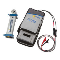
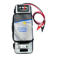
Equipment14
-
-
-
Precautions29
-
Precautions34
-
-
-
-
-
-
Menu Bar70
-
File Menu70
-
New Project71
-
-
-
View Menu80
-
Utility Menu80
-
Help Menu84
-
-
Introduction104
-
-
Mount Solsensor108
-
Alerts112
-
Data Backup113
-
-
-
Introduction122
-
-
-
Introduction134
-
Notches or Steps139
-
Low Current141
-
Uniform Soiling142
-
Strip Shade142
-
Dirt Dam142
-
-
Low Voltage144
-
Rounder Knee146
-
Advertisement
Solmetric PVA-1500V4 User Manual (150 pages)
PV Analyzer I-V Curve Tracer
Brand: Solmetric
|
Category: Measuring Instruments
|
Size: 4 MB
Table of Contents
-
Overview13
-
Equipment15
-
Cleaning23
-
Cleaning24
-
Cleaning25
-
Cleaning27
-
Cleaning28
-
Precautions30
-
Precautions35
-
Menu Bar71
-
File Menu71
-
New Project72
-
View Menu80
-
Utility Menu80
-
Help Menu83
-
Traces Tab84
-
History Tab90
-
Meg Test Tab91
-
Introduction101
-
Mount Solsensor104
-
Introduction117
-
Albedo Effects120
-
Diffuse Light120
-
Introduction129
-
Fill Factor130
-
Notches or Steps134
-
Low Current136
-
Uniform Soiling137
-
Strip Shade137
-
Dirt Dam137
-
Low Voltage139
-
Rounder Knee141
Solmetric PVA-1500V4 User Manual (128 pages)
I-V CURVE TRACER
Brand: Solmetric
|
Category: Measuring Instruments
|
Size: 4 MB
Table of Contents
-
Overview12
-
Equipment13
-
Cleaning20
-
Cleaning21
-
Precautions22
-
Menu Bar51
-
File Menu51
-
New Project52
-
View Menu60
-
Utility Menu60
-
Help Menu64
-
Traces Tab65
-
History Tab70
-
Meg Test Tab72
-
Introduction83
-
Alerts91
-
Data Backup92
-
Thermal Fuse100
-
Introduction101
-
Albedo Effects104
-
Diffuse Light104
-
Introduction111
-
Fill Factor112
-
Notches or Steps116
-
Low Current118
-
Uniform Soiling119
-
Strip Shade119
-
Dirt Dam119
-
Low Voltage121
-
Rounder Knee122
Advertisement

Solmetric PVA-1500V4 Quick Reference Card (2 pages)
Brand: Solmetric
|
Category: Measuring Instruments
|
Size: 0 MB