Sign In
Upload
Manuals
Brands
SICK Manuals
Security Sensors
nanoScan3 I/O
SICK nanoScan3 I/O Manuals
Manuals and User Guides for SICK nanoScan3 I/O. We have
5
SICK nanoScan3 I/O manuals available for free PDF download: Operating Instructions Manual, Mounting Instructions
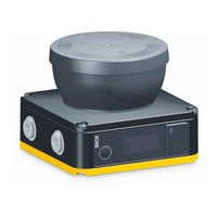
SICK nanoScan3 I/O Operating Instructions Manual (140 pages)
Safety laser scanner
Brand:
SICK
| Category:
Safety Equipment
| Size: 12 MB
Table of Contents
Table of Contents
3
About this Document
7
Scope
7
Target Groups of These Operating Instructions
7
Further Information
7
Symbols and Document Conventions
7
Target Groups and Selected Sections of These Operating Instructions
7
Safety Information
9
General Safety Notes
9
Laser Class 1
9
Intended Use
10
Inappropriate Use
10
Requirements for the Qualification of Personnel
10
Structure and Function
12
Device Overview
12
Product Description
12
Principle of Time-Of-Flight Measurement
13
Light Pulses Scan an Area
13
Product Characteristics
14
Variants
14
System Plug
14
Field Types
15
Example Applications
15
Field Types and Their Function
15
Hazardous Area Protection: Detection of the Presence of a Person in the Hazard- Ous Area
16
Hazardous Point Protection: Hand Detection
16
Access Protection: Detection of a Person When Accessing a Hazardous Area
17
Mobile Hazardous Area Protection: Detection of a Person When a Vehicle Approaches
17
Design
18
Operating Entity of the Machine
18
Manufacturer of the Machine
18
Project Planning
18
Protection from Interference
19
Prevent Crawling Beneath
19
Prevent Stepping over
19
Preventing Unprotected Areas
20
Unsecured Areas
20
Reference Contour Monitoring
21
Overrun of the Protective Field in Front of an Opening
22
Monitoring Case Switching Time
23
Tolerance Band of the Contour as Reference Field
23
Tected Opening, Edge of the Protected Opening = Reference Contour)
23
Minimum Distance for Stationary Applications
24
Stationary Application with Horizontal Scan Plane for Hazardous Area Protection.25
25
Hazardous Area Protection
25
Supplement Z R for Reflection-Based Measurement Errors
25
Protection against Reaching over with Low Scan Plane (Dimensions in MM)
26
Protection against Reaching over with High Scan Plane (Dimensions in MM)
27
Scan Plane at Calf Height
28
Hazardous Point Protection
29
Distance of the Protective Field from the Wall
29
Stationary Application in Vertical Operation for Hazardous Point Protection
30
Access Protection
31
Stationary Application in Vertical Operation for Access Protection
32
Mobile Hazardous Area Protection
33
Mobile Application in Horizontal Operation for Hazardous Area Protection
33
Flat-Rate Supplement for Lack of Ground Clearance
34
Minimum Supplement for Lack of Ground Clearance
35
Stopping Distance as a Function of the Vehicle's Speed
35
Recommended Fitting Height for Inverted Mounting
37
Recommended Fitting Height
37
Integrating the Equipment into the Electrical Control
37
Voltage Supply
38
Electromagnetic Compatibility
38
USB Connection
39
Ossds
39
Dual-Channel and Isolated Connection of an OSSD Pair
39
Control Inputs
40
No Potential Difference between Load and Protective Device
40
Status of the Channels of the Control Inputs with Complementary Evaluation
41
True Vales with 1-Off-N-Evaluation with 2 Input Pairs (Example)
41
Universal Inputs, Universal Outputs, Universal I/Os
42
Restart Interlock
43
How the Restart Interlock Works (1): no One in Protective Field, Machine Operates
44
How the Restart Interlock Works (2): Person Detected in Protective Field, Safety Out- Put in off State
44
How the Restart Interlock Works (4): the Reset Pushbutton Must be Pressed before Restarting the Machine
45
External Device Monitoring (EDM)
45
How the Restart Interlock Works (3): Person in Hazardous Area, no Detection in Pro- Tective Field, Safety Output Still in off State
45
Testing Plan
46
Planning the Thorough Check During Commissioning and in Certain Situations
46
Planning the Regular Thorough Check
47
Notes on the Tests
48
Mounting
51
Safety
51
Unpacking
51
Fitting the System Plug
51
Mounting the Device
52
Mounting Safety Laser Scanner
52
Connecting Cable (Male Connector, M12, 8-Pin, A-Coded)
53
Connecting Cable with M12 Plug Connector, 8-Pin
53
Connecting
53
Safety
53
Electrical Installation
53
Connecting Cable with M12 Plug Connector, 17-Pin
54
Connecting Cable (Male Connector, M12, 17-Pin, A-Coded)
54
Pin Assignment of the Connecting Cable with 8-Pin M12 Plug Connector
54
Pin Assignment of the Connecting Cable with 17-Pin M12 Plug Connector
54
Connecting Cable with Flying Leads, 17-Wire
56
Pin Assignment of the Connecting Cable with Flying Leads, 17-Wire
56
Network Connection
57
Network Pin Assignment (M12 Female Connector, 4-Pin, D-Coding)
57
Network Pin Assignment
57
Projects
58
Installing Safety Designer
58
Safety Designer Configuration Software
58
Delivery State
58
Configuration
58
User Interface
59
Software Controls
59
User Groups
60
Settings
61
Configuration
61
Configuration
62
Type Code in Safety Designer
63
Overview
64
Network Settings
65
Ethernet
65
Reading Configuration
65
Identification
66
Application
66
Monitoring Plane
67
Recommended Multiple Sampling
68
Contour as Reference Field
69
Fields
70
Field Editor
70
Buttons on the Toolbar
71
Colors of the Field Types
72
Buttons for Field Sets
72
Creating Field Set Templates
73
Importing and Exporting Field Sets and Fields
73
Background Image
73
Manage Field Set Templates
73
Background Image
74
Editing Fields Using Coordinates
74
Settings for the Field Editor
74
Editing Fields Using Coordinates
75
Drawing in Points that Cannot be Monitored
76
Enable Propose Field
76
Area that Cannot be Monitored
76
Mask Areas
76
Propose Field
77
Inputs and Outputs, Local
78
Outputs
79
Inputs
79
Further Settings for some Signals
80
Monitoring Cases
81
Settings for Monitoring Case Tables
82
Empirical Values for the Required Input Delay
82
Input Condition
83
Settings for Monitoring Cases
83
Several Monitoring Case Tables
83
Cut-Off Paths
84
Field Sets
84
Simulation
85
Data Output
86
Transferring a Configuration
87
Verify Configuration
87
Starting and Stopping Safety Function
88
Report
89
Service
90
Restart Device
90
Factory Settings
90
Managing Passwords
91
Optics Cover Calibration
91
Alignment
93
Switching on
93
Commissioning
93
Overview
93
Safety
93
Check During Commissioning and Modifications
94
Operation
95
Safety
95
Regular Thorough Check
95
Status Indicators
95
Status Indicator with the Display
96
Status Leds
96
Overview of Status Information
97
Maintenance
100
Safety
100
Regular Cleaning
100
Replacing the Optics Cover
101
Replacing the Safety Laser Scanner
103
Replacing the Safety Laser Scanner Without System Plug
103
Replacing the Safety Laser Scanner with System Plug
104
Replacing the System Plug
104
Regular Thorough Check
105
Troubleshooting
106
Safety
106
Detailed Diagnostics Using the Display
106
Fault Indication on the Display
107
Error Types
107
Diagnostics Using Safety Designer
109
Data Recorder
110
Event History
111
Print Message History or Save as a PDF
113
Message History
113
Decommissioning
114
Disposal
114
Technical Data
115
Version Numbers and Functional Scope
115
Data Sheet
115
Nanoscan3 I/O
115
Functional Scope
115
Revision
115
Features
115
Safety-Related Parameters
116
Interfaces
116
Electrical Data
117
Mechanical Data
118
Miscellaneous Data
119
Ambient Data
119
Response Times
120
Course of the OSSD Test over Time
120
Sensing Range
121
Protective Field Range
121
Dimensional Drawings
124
Ordering Information
125
Scope of Delivery
125
Spare Parts
126
Additional Spare Parts
126
Accessories
127
System Plug
127
Ordering Information, Test Rods
128
Cleaning Agent Ordering Information
128
Alignment Aid Ordering Information
128
Test Rods
128
Brackets Ordering Information
128
Cleaning Agent
128
Alignment Aid
128
Brackets
128
Glossary
129
Annex
133
Conformities and Certificates
133
EU Declaration of Conformity
133
UK Declaration of Conformity
133
Note on Standards
133
Licenses
135
Checklist for Initial Commissioning and Commissioning
136
List of Figures
137
List of Tables
139
Advertisement
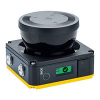
SICK nanoScan3 I/O Operating Instructions Manual (160 pages)
Safety laser scanners
Brand:
SICK
| Category:
Scanner
| Size: 11 MB
Table of Contents
Table of Contents
3
About this Document
8
Scope
8
Target Groups of These Operating Instructions
8
Further Information
8
Symbols and Document Conventions
8
Safety Information
10
General Safety Notes
10
Intended Use
11
Inappropriate Use
11
Cybersecurity
11
Requirements for the Qualification of Personnel
12
Product Description
13
Device Overview
13
Structure and Function
13
Product Characteristics
15
Variants
15
System Plug
15
Field Types
15
Example Applications
16
Project Planning
19
Manufacturer of the Machine
19
Operating Entity of the Machine
19
Design
19
Protection from Interference
20
Preventing Unprotected Areas
21
Reference Contour Monitoring
22
Monitoring Case Switching Time
24
Minimum Distance for Stationary Applications
25
Supplement Z R for Reflection-Based Measurement Errors
26
Hazardous Area Protection
26
Hazardous Point Protection
30
Access Protection
32
Mobile Hazardous Area Protection
34
Integrating the Equipment into the Electrical Control
38
Electromagnetic Compatibility
39
Voltage Supply
39
USB Connection
39
Control Inputs
40
Ethernet/Ip
41
Restart Interlock
41
Integration into the Network
43
Network Services and Ports
43
Integration of the Safety Laser Scanner into the Network
44
Configuring Control
45
Available Data
48
Assemblies
48
Testing Plan
50
Planning the Thorough Check During Commissioning and in Certain Situations
51
Planning the Regular Thorough Check
52
Notes on the Tests
52
Mounting
55
Safety
55
Unpacking
55
Fitting the System Plug
55
Mounting the Device
56
Electrical Installation
57
Safety
57
Connecting
57
Connecting Cable with M12 Plug Connector, 4-Pin
57
Network Connection
57
Configuration
59
Delivery State
59
Safety Designer Configuration Software
59
Installing Safety Designer
59
Projects
59
User Interface
60
User Groups
61
Settings
62
Configuration
62
Overview
65
Network Settings
66
Ethernet/Ip
66
Time Synchronization
67
Reading Configuration
67
Identification
67
Protocol Settings
68
Ethernet/Ip
68
Application
68
Monitoring Plane
69
Contour as Reference Field
71
Fields
72
Creating Field Set Templates
75
Importing and Exporting Field Sets and Fields
75
Background Image
75
Settings for the Field Editor
76
Editing Fields Using Coordinates
76
Drawing in Points that Cannot be Monitored
78
Enable Propose Field
78
Inputs and Outputs
79
Monitoring Cases
81
Settings for Monitoring Case Tables
81
Several Monitoring Case Tables
83
Settings for Monitoring Cases
83
Input Condition
83
Cut-Off Paths
84
Field Sets
84
Simulation
85
Data Output
86
Transferring a Configuration
87
Verify Configuration
87
Starting and Stopping Safety Function
88
Ethernet/Ip Overview
88
Report
89
Service
90
Restart Device
90
Ethernet/Ip
90
Factory Settings
90
Managing Passwords
91
Access Management
91
Optics Cover Calibration
92
Compare Configuration
93
Commissioning
95
Safety
95
Overview
95
Alignment
95
Switching on
95
Check During Commissioning and Modifications
96
Operation
97
Safety
97
Regular Thorough Check
97
Status Indicators
97
Status Indicator with the Display
98
Maintenance
102
Safety
102
Regular Cleaning
102
Replacing the Optics Cover
103
Replacing the Safety Laser Scanner
105
Replacing the Safety Laser Scanner Without System Plug
105
Replacing the Safety Laser Scanner with System Plug
106
Replacing the System Plug
106
Regular Thorough Check
107
Troubleshooting
108
Safety
108
Detailed Diagnostics Using the Display
108
Error Indication on the Display
109
Diagnostics Using Safety Designer
111
Data Recorder
111
Event History
112
Message History
114
Status Inputs and Outputs
115
Diagnostics Using the Control
115
Decommissioning
116
Disposal
116
Technical Data
117
Version Numbers and Functional Scope
117
Data Sheet
117
Response Times
121
Sensing Range
121
Data Exchange in the Network
124
Assemblies
124
Standard Objects (Open Objects)
132
Manufacturer-Specific Objects (Vendor-Specific Objects)
137
Dimensional Drawings
142
Ordering Information
143
Scope of Delivery
143
Spare Parts
144
Additional Spare Parts
144
Accessories
145
System Plug
145
Brackets
145
Alignment Aid
145
Cleaning Agent
145
Test Rods
145
Glossary
146
Annex
150
Conformities and Certificates
150
EU Declaration of Conformity
150
UK Declaration of Conformity
150
Note on Standards
150
Licenses
152
Checklist for Initial Commissioning and Commissioning
153
List of Figures
154
List of Tables
156
SICK nanoScan3 I/O Operating Instructions Manual (36 pages)
URCap; Safety System
Brand:
SICK
| Category:
Scanner
| Size: 1 MB
Table of Contents
Table of Contents
3
1 About this Document
5
Scope
5
Symbols and Document Conventions
5
Further Information
6
2 Safety Information
7
General Safety Note
7
Intended Use
7
Requirements for the Qualification of Personnel
7
3 Product Description
8
Design
8
Functionality
8
Requirements on the Application
8
4 Project Planning
9
Design
9
Position of the Safety Laser Scanner
9
Protective Field Design
9
Calculating Value for Stop Field Radius
9
Calculating Value for Reduced Field Radius
11
Position of the Robot
12
Warning Field
12
Testing Plan
13
5 Installation
14
Installing Nanoscan3 Tool - Urcap
14
6 Configuration
15
Requirements for Software and Functional Scope
15
Configuration of the Robot Controller
15
Setting Password for Switching Operating Modes
15
Configuring Inputs of the Robot Controller
15
Configuring Network
16
Configuring the Safety Laser Scanner
17
Starting Nanoscan3 Tool Configuration Software
17
Configuration in 2 Steps
17
General Configuration
17
Logging in
17
Configuring Table
18
Configuring Position of the Robot
18
Configuring Mode and Distances for Field Generation
18
Configuring Information for Application
19
Assigning Passwords for the Service Technician or Operator
20
Configuring the Safety Laser Scanner
20
Verifying Settings
23
Configuration of Fields
23
Checking Requirements for Configuration of Fields
23
Teaching in Area
24
Defining Walls
24
Drawing Fields Manually
25
Transferring Configuration to Device
26
Checking Configuration
26
7 Commissioning
28
Safety
28
Performing Commissioning at a New Location
28
8 Troubleshooting
30
Error Messages on the Start Screen
30
Carry out Diagnosis
30
Displaying Last Verified Report
30
9 Technical Data
31
Data Sheet
31
10 Ordering Information
32
Scope of Delivery
32
11 Accessories
33
Connectivity
33
12 Glossary
34
Advertisement
SICK nanoScan3 I/O Mounting Instructions (22 pages)
Safety laser scanner
Brand:
SICK
| Category:
Scanner
| Size: 2 MB
Table of Contents
Zu diesem Dokument
3
Zu Ihrer Sicherheit
3
Gerät Montieren
4
About this Document
13
Safety Information
13
Device Overview
13
Mounting the Device
14
Pin Assignment
14
Replacing the Safety Laser Scanner
19
Replacing the System Plug
20
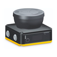
SICK nanoScan3 I/O Mounting Instructions (10 pages)
optics cover
Brand:
SICK
| Category:
Measuring Instruments
| Size: 0 MB
Table of Contents
Zu diesem Dokument
3
Zu Ihrer Sicherheit
3
About this Document
7
Safety Information
7
Replacing the Optics Cover
7
Advertisement
Related Products
SICK NAV350
SICK NAV-LOC
SICK NAV310
SICK NAV245
SICK NAV210
SICK NAV200
SICK Categories
Accessories
Security Sensors
Measuring Instruments
Scanner
Barcode Reader
More SICK Manuals
Login
Sign In
OR
Sign in with Facebook
Sign in with Google
Upload manual
Upload from disk
Upload from URL