Sign In
Upload
Manuals
Brands
SICK Manuals
Measuring Instruments
NAV200
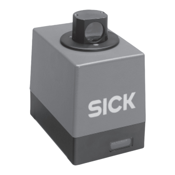
User Manuals: SICK NAV200 Laser Positioning System
Manuals and User Guides for SICK NAV200 Laser Positioning System. We have
1
SICK NAV200 Laser Positioning System manual available for free PDF download: Operating Instructions Manual
SICK NAV200 Operating Instructions Manual (84 pages)
Laser Positioning System for Navigational Support
Brand:
SICK
| Category:
Measuring Instruments
| Size: 1 MB
Table of Contents
Table of Contents
5
About this Document
11
Function of this Document
11
Target Groups
11
Assembly, Electrical Installation, Device Replacement
11
Commissioning, Configuration, Maintenance
11
Operation
11
Level of Information
11
Symbols Used
12
Safety Information
13
Authorized Personnel
13
Assembly and Maintenance
13
Electrical Installation and Device Replacement
13
Commissioning, Operation and Configuration
13
Intended Use
13
General Safety Information and Protective Measures
14
RF Interference
14
Electrical Installation Work
14
Laser Radiation
14
Fig. 2-1: Window Area in the Scanner Head of the NAV200
14
Quick Stop and Quick Start
15
Switching the NAV200 off
15
Switching the NAV200 on Again
15
Fig. 2-2: Laser Warning Label Attached to the NAV200
15
Environmental Aspects
16
Energy Consumption
16
Disposal after Final Removal from Service
16
Product Description
17
Design of the System
17
Scope of Delivery (Without Data Cable)
17
Fig. 3-1: NAV200 Laser Positioning System with Accessories (Included in Scope of Delivery)
17
System Requirements
18
Product Features and Functions (Overview)
18
Applications
19
View of the Device
20
Fig. 3-2: Arrangement of the NAV200
20
How the NAV200 Works
21
Fig. 3-3: Position Measurement of the NAV200 by Detection of Reflector Arrangements
21
Operating Conditions
22
Installation Requirements
22
Designing Reflector Arrangements
22
Reflectors
22
Fig. 3-4: Detection Angle with 100 MM (3.88 In) Wide Reflector Strips Made of Diamond Grade 3000X Reflective Film (0° = Vertical Striking of the Measurement Beam)
23
Fig. 3-5: Alignment of Diamond Grade 3000X Reflective Film, Production Date before July 2002
24
Fig. 3-6: Alignment of Diamond Grade 3000X Reflective Film, Production Date
24
Designing Layers
25
Fig. 3-7: Vertical Centre Line with Flat Reflectors and Vertical Central Axis with Cylindrical Reflectors
25
Fig. 3-8: Absolute and Local Co-Ordinate System with Angular Position of the NAV200
25
Fig. 3-9: Common Use of Reflectors of Two Adjoining Layers
26
Reflector Arrangements Within a Layer
27
Fig. 3-10: Correct, Asymmetrical Arrangement of Reflectors in the Layer
27
Fig. 3-11: Incorrect, Symmetrical Arrangement of Reflectors in the Layer
27
Measurement Accuracy
28
Fig. 3-12: Example; Low Positioning Accuracy Without the "N Closest" Function and Without the "Radii of Action" Function
28
Fig. 3-13: Example: Higher Positioning Accuracy with the "N Closest" Function and with the "Radius of Action" Function
29
How the NAV200 Deals with Sources of Error
30
Fig. 3-14: Overlapping of Two Reflectors with an Angle of Less than
30
Fig. 3-15: Minimum Distance from Reflectors to Other Reflective Objects
31
Measurement and Entry of the Reflector Co-Ordinates
32
Integration of the NAV200 in a Navigation System
32
Data Interface
33
Fig. 3-16: Integration of the NAV200 in a Navigation System
33
Fig. 3-17: Data Communication between NAV200 and Vehicle Computer of the AGV
33
Measurement Quality as an Indicator of the Reliability of the Positional Data
34
Position Measurement ("Positioning Operation" Mode)
35
Fig. 3-18: Identification of Reflectors in "Quickmap" Operating Condition
35
Reflector Co-Ordinates" Mode
36
Fig. 3-19: Travel Along a Route with Loss of All Other Reflectors
36
Fig. 3-20: Travel Along a Narrow Aisle by Means of the "Reflector Co-Ordinates" Mode
36
Displays and Controls
37
Controls
37
Function of the Leds on the NAV200
37
Tab. 3-1: NAV200: Meaning of the Leds
37
Fig. 3-21: NAV200: Position of the Leds on the NAV200
37
Installation
39
Overview of the Installation Steps
39
Preparation for Installation of the NAV200
39
Ensure that You Have All the Required Components
39
Preparing the Accessories
39
Selecting Mounting Position and Installation Location for the NAV200
39
Mounting the Device
40
Mounting
40
Mounting Additional Components
40
Assembly and Mounting of the Reflectors
40
Disassembling the System
40
Electrical Installation
41
Overview of the Installation Steps
41
Electrical Connections and Cables
41
Conductor Cross-Sections
41
Cables
41
Screening Concept
41
Fig. 5-1: Screening Concept of the NAV200
41
Pin Assignment of the Connections
42
Power Supply" Device Plug
42
RS 232 Data Interface" Device Plug
42
Tab. 5-1: Pin Assignment of the 8-Pin Chassis-Mount Plug for Connecting the Power Supply
42
Tab. 5-2: Pin Assignment of the 14-Pin Chassis-Mount Plug for Connecting
42
Power Cord
43
RS 232 Data Cable
43
Tab. 5-3: Pin Assignment of the 8-Pin Cable Socket for Connecting the Power Supply, View of the Soldered Connections
43
Tab. 5-4: Pin Assignment of the RS 232 Data Cable 9-Pin D-Sub Socket
43
Fig. 5-2: Assembled RS 232 Data Cable No. 6024723/No. 2030334
43
Preparations for Electrical Installation
44
Conditions for the Data Interface
44
Power Supply
44
Tab. 5-5: Maximum Cable Length between NAV200 and Vehicle Computer
44
Carrying out the Electrical Installation
45
Tools and Equipment
45
Connecting the NAV200 to the PC and Vehicle Computer
45
Connecting the Power Supply
45
The RS 232 Data Cable
45
Fig. 5-3: Wiring of the RS 232 Data Cable
45
Fig. 5-4: Wiring of the Cable Socket for the Power Supply
45
Operation
47
Overview of the Commissioning Steps
47
Default Settings of the NAV200 Setup Configuration Software
47
Tab. 6-1: Default Settings of the NAV200 Setup Configuration Software
47
Quick Start
48
Fig. 6-1: Quick Start with Mapping Operation
49
NAV200 Setup Configuration Software
50
Configuring the NAV200 with the NAV200 Setup Software
50
Installation of the NAV200 Setup Configuration Software
50
Software Functions (Overview)
51
Overview of the Configuration Steps
51
Starting the NAV200 Setup Software
51
Fig. 6-2: Interface Parameters in the Status Bar of NAV200 Setup
52
User Interface of the NAV200 Setup Configuration Software
53
Fig. 6-3: Program Window of the NAV200 Setup Configuration Software
53
Fig. 6-4: Selecting the Three Types of Display of the Graphics Window
54
Fig. 6-5: the same Reflector Arrangement Displayed in the Cartesian Co-Ordinate System and in the Polar Co-Ordinate System
55
Fig. 6-6: Data Display: "Distance against Angle" (Extract from the Layer Table and Part of the Graphics Window)
55
Toolbar Commands
56
Tab. 6-2: NAV200 Setup: Function of the Buttons in the Toolbar
56
Project Files and Reflector Data
57
Fig. 6-7: "Project Settings" Dialog Box
57
Fig. 6-8: "Reflector Data" Text File
58
Fig. 6-9: Layer Selection for Data Transfer
59
Closing the NAV200 Setup Configuration Software
60
Fig. 6-10: Icons in the NAV and PROJECT Columns of the Layer Table
60
NAV200 Operating Modes
61
Standby
61
Mapping
61
Download
61
Upload
61
Position Measurement
61
Reflector Co-Ordinates
62
Performing and Testing the Configuration
63
Measuring, Entering and Transferring the Exact Reflector Co-Ordinates Manually and Testing Positioning Operation
63
Fig. 6-11: Dialog Box for Loading Data "Reflector Data" Text File in NAV200 Setup
63
Fig. 6-12: Activating Edit Mode for Reflector Data
64
Fig. 6-13: Dialog Box: Data Entry for Positioning Operation
65
Fig. 6-14: Program Window During Positioning Operation ("Positioning Operation" Mode)
66
Measuring and Reading the Reflector Co-Ordinates Automatically Using the Nav200'S Mapping
67
Fig. 6-15: Dialog Box for the Mapping Parameters after Data Entry
67
Fig. 6-16: Information Box During Mapping
68
Fig. 6-17: NAV200 Setup Feedback and Processing of Mapping Results
68
Fig. 6-18: Program Window after Completion of Mapping
69
Logging the Data Communication (Log File)
71
Updating the Firmware
71
Switching the NAV200 off
71
Maintenance
73
Maintenance During Operation
73
Cleaning the Front Pane of the NAV200
73
Maintenance
74
Disposal
74
Fig. 7-1: Cleaning the Front Pane on the NAV200
74
Troubleshooting
75
Overview of Possible Errors and Malfunctions
75
Mounting Errors
75
Electrical Installation Errors
75
Parameter Setting Error
75
Operational Malfunctions
75
Monitoring Errors and Fault Signs
75
SICK Support
75
Technical Data
77
NAV200 Data Sheet
77
Tab. 9-1: NAV200 Technical Specifications
77
NAV200 Dimensional Drawing
78
Fig. 9-1: Dimensional Drawing of the NAV200
78
Appendix
79
Overview of the Appendices
79
Available Accessories
80
Mounting Accessories
80
Accessories for Reflectors
80
Cables and Connectors
80
Tab. 10-1: Mounting Accessories Available
80
Tab. 10-2: Accessories Available for Reflectors
80
Tab. 10-3: Available Accessories Cables and Connectors
80
Supplementary Documentation
81
Tab. 10-4: Supplementary Documentation for the NAV200
81
Replacing a NAV200
82
Replacing a NAV200 with Backed-Up Configuration Data
82
Reproduction of the EC Declarations of Conformity
83
EC Declaration of Conformity for NAV200
83
Fig. 10-1: Reproduction of the EC Declaration of Conformity for NAV200 (Page 1, Reduced)
83
Advertisement
Advertisement
Related Products
SICK NAV-LOC
SICK NAV310
SICK NAV350
SICK NAV245
SICK NAV210
SICK nanoScan3 I/O
SICK 1042266
SICK 1042267
SICK 1088784
SICK 1106166
SICK Categories
Accessories
Security Sensors
Measuring Instruments
Scanner
Barcode Reader
More SICK Manuals
Login
Sign In
OR
Sign in with Facebook
Sign in with Google
Upload manual
Upload from disk
Upload from URL