Sign In
Upload
Manuals
Brands
Rigol Manuals
Test Equipment
DHO4404
Rigol DHO4404 Manuals
Manuals and User Guides for Rigol DHO4404. We have
3
Rigol DHO4404 manuals available for free PDF download: User Manual, Performance Verification Manual, Quick Manual
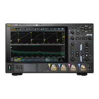
Rigol DHO4404 User Manual (302 pages)
Digital
Brand:
Rigol
| Category:
Test Equipment
| Size: 22 MB
Table of Contents
Table of Contents
3
Section Description
3
Safety Requirement
17
General Safety Summary
17
Safety Notices and Symbols
19
Measurement Category
19
Ventilation Requirement
20
Working Environment
20
Care and Cleaning
22
Environmental Considerations
22
Product Features
24
Document Overview
25
Quick Start
27
General Inspection
27
Appearance and Dimensions
28
Figure 4.1 Front View
28
Figure 4.2 Side View
28
To Prepare for Use
29
Tilting the Oscilloscope for Easier Viewing
29
Connecting to Power
29
Figure 4.3 Flipping In/Out Tabs
29
Figure 4.4 Connecting to Power
29
Turn-On Checkout
30
Replacing the Fuse
30
Setting the System Language
31
Connecting Probes
31
Figure 4.5 Replacing the Fuse
31
Figure 4.6 Connecting the Passive Probe
32
Figure 4.7 Connecting the Probe Head to the PA of the Active Probe
32
Function Inspection
33
Figure 4.8 Connecting the Active Probe
33
Probe Compensation
34
Figure 4.9 Using the Compensation Signal
34
Figure 4.10 Square Waveform Signal
34
Product Overview
35
Figure 4.11 Probe Compensation
35
Front Panel Overview
36
Figure 4.12 Front Panel
36
Menu Operation
37
Rear Panel Overview
42
Figure 4.13 Rear Panel
42
User Interface Overview
44
Figure 4.14 User Interface
44
Touch Screen Gestures
46
Tap
46
Pinch&Stretch
47
Drag
47
Figure 4.15 Tap Gesture
47
Figure 4.16 Pinch&Stretch Gesture
47
Parameter Setting Method
48
Figure 4.17 Drag Gesture
48
Figure 4.18 English Input Interface
49
Figure 4.19 Chinese Input Interface
50
Figure 4.20 String Keypad
52
Figure 4.21 Numeric Keypad
53
Using the Security Lock
54
Accessing the Built-In Help System
54
Figure 4.22 to Use the Security Lock
54
Viewing the Option Information and Install the Option
55
Vertical System
57
To Enable or Disable the Analog Channel
57
Figure 5.1 Vertical Menu
57
To Adjust the Vertical Scale
59
To Adjust the Vertical Offset
60
To Specify Channel Coupling
61
To Specify Bandwidth Limit
61
To Specify Input Impedance
62
Table 5.1 Bandwidth Limit
62
To Invert a Waveform
63
Figure 5.2 Switched Input Impedance
63
To Set Probe
64
Figure 5.3 Waveform Invert On/Off
64
Figure 5.4 Probe Setting Menu
65
Figure 5.5 Active Probe Setting Menu
65
Table 5.2 Probe Ratio
66
To Specify the Amplitude Unit
67
To Adjust Bias
67
To Specify the Skew
68
To Turn the Channel Label Display On/Off
69
Figure 5.6 Zero Offset
69
Horizontal System
70
To Adjust the Horizontal Time Base
70
Figure 6.1 Horizontal Menu
70
To Adjust the Horizontal Position
71
Zoom Mode (Delayed Sweep)
72
Figure 6.2 Zoom Mode
73
Acquisition System
75
Acquisition Mode
75
Figure 7.1 Horizontal Menu
75
Figure 7.2 Display Modes
77
Sampling Mode
78
Sample Rate
78
Memory Depth
79
Figure 7.3 Memory Depth
80
Horizontal Expansion Reference
81
Roll Mode
81
XY Mode
82
Figure 7.4 XY Menu
83
Figure 7.5 Measurement Schematic Diagram of Phase Deviation
84
Triggering the Oscilloscope
85
Trigger Source
85
Trigger Level
86
Trigger Mode
87
Figure 8.1 Schematic Diagram of the Acquisition Memory
87
Trigger Coupling
88
Trigger Holdoff
89
Noise Rejection
89
Figure 8.2 Trigger Holdoff
89
Trigger Type
90
Edge Trigger
90
Figure 8.3 Edge Trigger Setting Menu
90
Pulse Width Trigger
92
Figure 8.4 Positive/Negative Pulse Width
92
Figure 8.5 Pulse Width Trigger Setting Menu
92
Slope Trigger
94
Figure 8.6 Positive Slope Time/Negative Slope Time
95
Figure 8.7 Slope Trigger Setting Menu
95
Video Trigger
97
Figure 8.8 Video Trigger Setting Menu
98
Table 8.1 Video Standard
99
Pattern Trigger
100
Figure 8.9 Pattern Trigger
100
Figure 8.10 Pattern Trigger Setting Menu
101
Duration Trigger
102
Figure 8.11 Duration Trigger
103
Figure 8.12 Duration Trigger Setting Menu
103
Timeout Trigger
105
Figure 8.13 Timeout Trigger
105
Figure 8.14 Timeout Trigger Menu
106
Runt Trigger
107
Figure 8.15 Runt Trigger
107
Figure 8.16 Runt Trigger Setting Menu
108
Window Trigger
110
Figure 8.17 Window Trigger Setting Menu
110
Delay Trigger
112
Figure 8.18 Delay Trigger
112
Figure 8.19 Delay Trigger Setting Menu
112
Setup/Hold Trigger
114
Figure 8.20 Setup/Hold Trigger
115
Figure 8.21 Setup/Hold Trigger Setting Menu
115
Nth Edge Trigger
117
Figure 8.22 Nth Edge Trigger
117
Figure 8.23 Nth Edge Trigger Setting Menu
118
RS232 Trigger
119
Figure 8.24 Schematic Diagram of RS232 Protocol
119
Figure 8.25 RS232 Trigger Setting Menu
120
I2C Trigger
122
Figure 8.26 Sequence Diagram of I2C Protocol
122
Figure 8.27 I2C Trigger Setting Menu
123
Figure 8.28 Binary Format Setting
124
Figure 8.29 Hexadecimal Format Setting
125
SPI Trigger
126
Figure 8.30 Sequential Chart of SPI Bus
126
Figure 8.31 SPI Trigger Setting Menu
126
CAN Trigger
128
Figure 8.32 Data Frame Format of the CAN Bus
129
Figure 8.33 CAN Trigger Setting Menu
129
Figure 8.34 Sample Position
130
Flexray Trigger (Optional)
132
Figure 8.35 Frame Format of Flexray Bus
132
Figure 8.36 Flexray Trigger Setting Menu
133
LIN Trigger (Optional)
135
Figure 8.37 Data Frame Format of the LIN Bus
135
Figure 8.38 LIN Trigger Setting Menu
135
Figure 8.39 Sample Position
136
I2S Trigger (Optional)
137
Figure 8.40 Sequential Chart of I2S Bus
138
Figure 8.41 I2S Trigger Setting Menu
138
MIL-STD-1553 Trigger (Optional)
141
Figure 8.42 Formats of the Command Word, Data Word, and Status Word of
142
Figure 8.43 MIL-STD-1553 Trigger Setting Menu
142
Trigger Output Connector
145
Math Operation
146
Figure 9.1 Math Menu
146
Arithmetic Operation
147
Figure 9.2 Waveform Display Window of the Operation Results
147
Figure 9.3 Arithmetic Operation Menu
148
Figure 9.4 Operation Result Display Window
148
Function Operation
150
Figure 9.5 Function Operation Menu
151
Figure 9.6 Operation Result Display Window
152
FFT Operation
154
Figure 9.7 FFT Operation Menu
154
Figure 9.8 FFT Operation Window
155
Table 9.1 Window Function
156
Figure 9.9 Peak Search
158
Logic Operation
159
Figure 9.10 Logic Operation Menu
159
Figure 9.11 Operation Result Display Window
160
Table 9.2 Logic Operation
160
Digital Filter
162
Figure 9.12 Digital Filter Menu
163
Figure 9.13 Operation Result Display Window
163
Measurements
167
Auto Scale
167
Auto Measurements
168
Measurement Parameter
168
Time Parameters
169
Figure 10.1 Time Parameters
169
Count Values
170
Delay and Phase Parameters
172
Figure 10.2 Delay and Phase Parameters
172
Voltage Parameters
173
Figure 10.3 Voltage Parameters
173
Other Parameters
175
Select the Measurement Item
175
Figure 10.4 Vertical Measurement Items
176
Figure 10.5 Horizontal Measurement Items
177
Figure 10.6 Other Measurement Items
177
Measurement Settings
178
Figure 10.7 Measurement Settings Menu
178
Remove the Measurement Results
181
Cursor Measurements
181
Figure 10.8 Cursors
181
Manual Mode
183
Figure 10.9 Manual Mode Setting Menu
183
Track Mode
185
Figure 10.10 Manual Cursor Measurement Example
185
Figure 10.11 Track Mode Setting Menu
186
Figure 10.12 Track Measurement (before Horizontal Expansion)
187
XY Mode
188
Figure 10.13 Track Measurement (after Horizontal Expansion)
188
Figure 10.14 XY Mode Setting Menu
189
Digital Voltmeter (DVM) and Frequency Counter
191
Digital Voltmeter (DVM)
191
Measurement Settings
192
Figure 11.1 DVM Setting Menu
192
Remove the Measurement
193
Frequency Counter
193
Measurement Settings
194
Figure 11.2 Frequency Counter Setting Menu
194
Reset Statistics
195
Remove the Measurement
195
Power Analysis (Optional)
196
Power Quality
196
Figure 12.1 UPA Menu
196
Ripple
198
Figure 12.2 Power Quality Analysis Results Display
198
Figure 12.3 Connection Diagram of Power Quality Analysis
198
Figure 12.4 Ripple Analysis Results Display
199
Figure 12.5 Connection Diagram of Ripple Analysis
200
Reference Waveform
201
To Enable Ref Function
201
To Set the Reference Waveform
201
Figure 13.1 Reference Waveform Menu
201
To Set the Ref Waveform Display
202
Export and Import Operation
203
Pass/Fail Test
205
To Enable or Disable the Pass/Fail Test Function
205
Figure 14.1 Pass/Fail Test Menu
205
To Select the Source
206
To Create a Mask
206
To Set the Output Form of the Test Results
206
To Start or Stop the Pass/Fail Test Operation
207
To Display the Statistics of the Test Results
208
Figure 14.2 Pass/Fail Test Interface
208
Protocol Decoding
210
Parallel Decoding
210
Figure 15.1 Schematic Diagram of Parallel Decoding
210
Clock Setting (CLK)
211
Figure 15.2 Parallel Decoding Menu
211
Bus Setting
212
Table 15.1 Bus Setting
212
Display-Related Settings
213
Event Table
213
Figure 15.3 Parallel Decoding Event Table
213
RS232 Decoding
214
Figure 15.4 Schematic Diagram of RS232 Serial Bus
214
Source Setting
215
Figure 15.5 RS232 Decoding Menu
215
To Set Data Package
216
Display-Related Settings
217
Event Table
217
I2C Decoding
218
Figure 15.6 RS232 Decoding Event Table
218
Source Setting
219
Figure 15.7 I2C Serial Bus
219
Figure 15.8 I2C Decoding Menu
219
Display-Related Settings
220
Event Table
220
Figure 15.9 I2C Decoding Event Table
221
SPI Decoding
222
Figure 15.10 SPI Serial Bus
222
Figure 15.11 SPI Decoding Menu
222
To Set the Source
223
To Set Mode and Data
223
Display-Related Settings
225
Event Table
225
Figure 15.12 SPI Decoding Event Table
225
CAN Decoding
226
Figure 15.13 CAN Decoding Menu
226
Signal Configuration
227
Display-Related Settings
228
Event Table
228
Figure 15.14 Sample Position
228
Figure 15.15 CAN Decoding Event Table
229
LIN Decoding (Optional)
230
Signal Configuration
230
Figure 15.16 LIN Decoding Menu
230
Display-Related Settings
231
Event Table
231
Figure 15.17 LIN Decoding Event Table
232
I2S Decoding (Optional)
233
Source Setting
233
Figure 15.18 I2S Decoding Menu
233
Bus Setting
234
Display-Related Settings
235
Event Table
235
Figure 15.19 I2S Decoding Event Table
235
Flexray Decoding (Optional)
236
Figure 15.20 Flexray Decoding Menu
236
Signal Configuration
237
Display-Related Settings
238
Event Table
238
Figure 15.21 Sample Position
238
Figure 15.22 Flexray Decoding Event Table
239
1553B Decoding (Optional)
240
Figure 15.23 1553B Decoding Menu
240
To Set the Data Channel Source and the Threshold
241
Display-Related Settings
241
Event Table
241
Figure 15.24 1553B Decoding Event Table
242
Multi-Pane Windowing
244
Figure 16.1 "Add Window" Menu
244
Waveform Recording and Playing
246
Common Settings
246
Figure 17.1 "Record" Menu
246
Record Options
247
Play Options
248
Figure 17.2 Minimized "Play" Menu
249
Search and Navigation
251
Search
251
Figure 18.1 Search Menu
251
Navigation
253
Figure 18.2 Marktable Display
253
Figure 18.3 Navigation Menu
254
Figure 18.4 Simplified Navigation Menu
254
Figure 18.5 "Search Event" Navigation Setting Menu
255
Figure 18.6 "Frame Segment" Navigation Setting Menu
255
Display Control
257
Display Type
257
Persistence Time
257
Figure 19.1 Display Setting Menu
257
Waveform Intensity
258
To Set the Screen Grid
258
Display Settings
258
Show Scale
259
Color Grade
259
Waveform Freeze
259
Store and Load
260
To Enter the Storage Menu
260
To Save a File
260
Save Image
260
Figure 20.1 Image Saving Setting Menu
261
Save Wave
262
Figure 20.2 Waveform Saving Setting Menu
263
Save Setup
264
Figure 20.3 Setup Saving Setting Menu
264
Binary Data Format (.Bin)
265
Table 20.1 bin File Format
265
Table 20.2 File Header
266
Table 20.3 Waveform Header
266
Load a File
268
Table 20.4 Waveform Data Header
268
Firmware Upgrade
269
Figure 20.4 Load Setting Menu
269
Disk Management
270
Figure 20.5 Upgrade Menu
270
Figure 20.6 Disk Management Interface
271
System Utility Function Setting
273
I/O Setting
273
Basic Settings
275
About this Oscilloscope
277
Other Settings
278
Auto Config
278
Selfcal
279
Figure 21.1 Self-Calibration Menu
279
Option List
280
Quick Action Settings
280
Figure 21.2 Quick Menu
280
Self-Check
282
Figure 21.3 Key Test Interface
282
Figure 21.4 Touch Screen Test Interface
283
Remote Control
284
Remote Control Via USB
285
Remote Control Via LAN
285
Remote Control Via GPIB
286
Figure 22.1 Search for the Available Device
287
Figure 22.2 Confirm the Available Device
287
Troubleshooting
288
Appendix
290
Appendix A: Options and Accessories
290
Appendix B: Warranty
291
Appendix C: Factory Settings
291
Table 24.2 Factory Settings
297
Advertisement
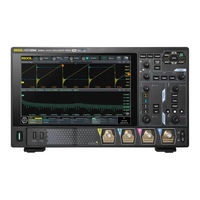
Rigol DHO4404 Performance Verification Manual (50 pages)
Digital oscilloscope
Brand:
Rigol
| Category:
Test Equipment
| Size: 1 MB
Table of Contents
Table of Contents
3
Safety Requirement
7
General Safety Summary
7
Safety Notices and Symbols
8
Specifications
10
Document Overview
12
Overview
14
Test Preparations
14
Test Result Record
15
Figure 4.1 Self-Calibration Menu
15
Specifications
16
Performance Verification Test
17
Random Noise Test
17
Specification
17
Test Procedures
18
Test Record from
19
Impedance Test
20
Specification
20
Test Connection Diagram
21
Test Procedures
21
Figure 5.1 Input Impedance Test Connection Diagram
21
Test Record from
22
Input Capacitance Test
23
Specification
23
Test Connection Diagram
23
Test Procedures
23
Figure 5.2 Input Capacitance Test Connection Diagram
23
Test Record from
24
DC Gain Accuracy Test
24
Specification
24
Test Connection Diagram
25
Test Procedures
25
Figure 5.3 DC Gain Accuracy Test Connection Diagram
25
Test Record from
27
DC Offset Accuracy Test
30
Specification
30
Test Connection Diagram
30
Test Procedures
30
Figure 5.4 DC Offset Accuracy Test Connection Diagram
30
Test Record from
31
Bandwidth Test
34
Specification
34
Test Connection Diagram
34
Test Procedures
34
Figure 5.5 Bandwidth Test Connection Diagram
34
Test Record from
37
Time Base Accuracy Test
38
Specification
38
Test Connection Diagram
38
Test Procedures
38
Figure 5.6 Time Base Accuracy Test Connection Diagram
38
Test Record from
40
Appendix: Test Record Form
41
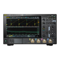
Rigol DHO4404 Quick Manual (31 pages)
Digital Oscilloscope
Brand:
Rigol
| Category:
Test Equipment
| Size: 3 MB
Table of Contents
Safety Requirement
3
General Safety Summary
3
Safety Notices and Symbols
3
Measurement Category
4
Ventilation Requirement
5
Working Environment
5
Care and Cleaning
6
Environmental Considerations
7
Document Overview
8
General Inspection
10
Product Overview
11
Front Panel Overview
11
Rear Panel Overview
12
User Interface Overview
13
To Prepare for Use
14
Tilting the Oscilloscope for Easier Viewing
14
Connecting to Power
14
Turn-On Checkout
15
Setting the System Language
16
Connecting Probes
16
Function Inspection
18
Probe Compensation
19
Touchscreen Gestures
21
Parameter Setting Method
25
Replacing the Fuse
27
Remote Control
28
More Product Information
29
Advertisement
Advertisement
Related Products
Rigol DHO4000 Series
Rigol DHO4204
Rigol DHO4804
Rigol DHO1000 Series
Rigol DHO1204
Rigol DHO1072
Rigol DHO802
Rigol DHO804
Rigol DHO812
Rigol DHO814
Rigol Categories
Test Equipment
Measuring Instruments
Portable Generator
Power Supply
Inverter
More Rigol Manuals
Login
Sign In
OR
Sign in with Facebook
Sign in with Google
Upload manual
Upload from disk
Upload from URL