Sign In
Upload
Manuals
Brands
Ricoh Manuals
All in One Printer
K-C1
Ricoh K-C1 Manuals
Manuals and User Guides for Ricoh K-C1. We have
2
Ricoh K-C1 manuals available for free PDF download: Service Manual
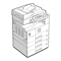
Ricoh K-C1 Service Manual (250 pages)
Brand:
Ricoh
| Category:
All in One Printer
| Size: 8.15 MB
Table of Contents
Service Manual
1
Important Safety Notices
2
Table of Contents
4
1 Installation
15
Installation Requirements
15
Environment
15
Machine Level
16
Minimum Space Requirements
17
Power Requirements
17
Copier Installation
18
Power Sockets for Peripherals
18
Accessory Check
18
Installation Procedure
19
Platen Cover Installation
22
Accessory Check
22
Installation Procedure
22
Ardf Installation
23
Accessory Check
23
Installation Procedure
23
Adf Installation
25
Accessory Check
25
Installation Procedure
25
Two-Tray Paper Tray Unit Installation
27
Accessory Check
27
Installation Procedure
27
One-Tray Paper Tray Unit Installation
30
Accessory Check
30
Installation Procedure
30
Imb Installation
33
Accessory Check
33
Installation Procedure
33
Dram Installation
34
Anti-Condensation Heater Installation
35
Tray Heaters
36
Upper Tray Heater
36
Lower Tray Heater (Two-Tray Model Only)
37
Tray Heaters for the Optional Paper Feed Units
38
Key Counter Installation
41
2 Preventive Maintenance Schedules
43
Pm Tables
43
How to Clear the Pm Counter
45
3 Replacement and Adjustment
46
General Cautions
46
Pcu (Photoconductor Unit)
46
Transfer Roller
46
Scanner Unit
46
Laser Unit
47
Fusing Unit
47
Paper Feed
47
Important
47
Special Tools and Lubricants
47
Exterior Covers & Operation Panel
48
Rear Cover
48
Rear Lower Cover (Two-Tray Models Only)
48
Copy Tray
49
Left Upper Cover
49
Front Upper Left Cover and Operation Panel
49
Right Upper Cover
49
Top Rear Cover
49
Left Cover
50
Front Long Cover
50
Front Right Cover
51
Right Rear Cover
51
Right Door
52
By-Pass Tray
53
Left Lower Cover (Two-Tray Models Only)
54
Right Lower Cover (Two-Tray Models Only)
54
Platen Cover Sensor
54
Scanner Section
55
Exposure Glass/Df Exposure Glass
55
Exposure Glass
55
DF Exposure Glass
55
Lens Block
56
Exposure Lamp, Lamp Stabilizer Board
56
Original Width Sensor
57
Original Length Sensor
57
Sensor Positions
57
Changing the Original Sensor Positions (8K/16K)
58
Procedure
59
Scanner Motor
60
Scanner H
60
Adjustment of 2Nd Scanner Position
61
Adjustment of 1St and 2Nd Scanner Alignment
62
Laser Unit
63
Location of "Caution" Decal
63
Toner Shield Glass
64
Laser Unit
64
Ld Unit
65
Polygonal Mirror Motor
65
Laser Unit Alignment Adjustment
66
Pcu Section
67
Pcu
67
Pick-Off Pawls
67
Toner Density Sensor
67
Opc Drum
68
Charge Roller and Cleaning Brush
69
Cleaning Blade
69
Developer
70
After Replacement or Adjustment
71
Toner Supply Motor
72
Paper Feed Section
73
Paper Feed Roller
73
Friction Pad
73
Paper End Sensor
73
Exit Sensor
74
Non-Duplex Models
74
Duplex Models
74
By-Pass Feed Roller and By-Pass Paper End Sensor
75
Registration Roller
76
Registration Clutch
77
Registration Sensor
78
Upper Paper Feed Clutch and By-Pass Feed Clutch
78
Relay Clutch
79
Relay Sensor
79
Lower Paper Feed Clutch
79
Vertical Transport Sensor
80
Paper Size Switch
80
Image Transfer
81
Image Transfer Roller
81
Image Density Sensor
81
Fusing
82
Fusing Unit
82
Thermistor
82
Fusing Lamp
83
Hot Roller
83
Thermofuse and Thermostat
84
Hot Roller Stripper Pawls
84
Pressure Roller and Bushings
85
Nip Band Width Adjustment
86
Duplex Unit (Duplex Models Only)
87
Duplex Exit Sensor
87
Duplex Entrance Sensor
87
Duplex Inverter Sensor
87
Duplex Transport Motor
88
Duplex Inverter Motor
88
Duplex Control Board
88
Other Replacements
89
Quenching Lamp
89
High-Voltage Power Supply Board
89
Imb (Memory Board)
90
Bicu (Base-Engine Image Control Unit)
90
Iob (I/O Board)
91
Main Motor
91
Rear Exhaust Fan
91
Left Exhaust Fan
92
Psu (Power Supply Unit)
92
Gearbox
93
Replacement Procedure
93
Gear Arrangement Within the Gearbox
94
Copy Adjustments: Printing/Scanning
95
Printing
95
Registration - Leading Edge/Side-To-Side
95
Blank Margin
96
Main Scan Magnification
96
Scanning
97
Registration: Platen Mode
97
Magnification
98
Standard White Density Adjustment
99
Adf Image Adjustment
100
Registration and Blank Margin
100
Sub-Scan Magnification
100
4 Troubleshooting
101
Service Call Conditions
101
Sc Code Descriptions
102
Electrical Component Defects
108
Sensors
108
Switches
109
Blown Fuse Conditions
110
Led Display
110
Bicu
110
Iob
110
5 Service Tables
111
Using Service Program Modes
111
Accessing SP Modes
111
Accessing Copy Mode from Within an SP Mode
111
How to Select a Program Number
112
To Input a Value or Setting for an SP Mode
112
Sp Mode Tables
113
SP1-XXX (Feed)
113
SP2-XXX (Drum)
116
SP4-XXX (Scanner)
121
SP5-XXX (Mode)
127
SP6-XXX (Peripherals)
134
SP7-XXX (Data Log)
136
Test Pattern Printing (Sp5-902)
141
Input Check (Sp5-803)
142
Output Check (Sp5-804)
146
Output Check Table
146
Copy Jam History (Sp7-903)
147
Smc Printing (Sp5-992)
148
Original Jam History Display (Sp7-905)
148
Memory All Clear (Sp5-801)
149
Using a Flash Memory Card
149
Without Using a Flash Memory Card
150
Program Upload/Download
151
Program Download (SP5-827)
151
Program Upload (SP5-826)
152
Nvram Data Upload/Download
153
NVRAM Data Download (SP5-825)
153
NVRAM Data Upload (SP5-824)
154
Adf Aps Sensor Output Display (Sp6-901)
156
Serial Number Input (Sp5-811)
157
ID Sensor Error Analysis (Sp2-221)
158
User Tools
159
How to Enter and Exit User Tools
159
User Tools Table
159
System Setting Table
159
Copy Features Table
160
6 Detailed Section Descriptions
161
Overview
161
Component Layout
161
Paper Path
163
Drive Layout
164
Board Structure
165
Block Diagram
165
Bicu (Base Engine and Image Control Unit)
166
IOB (I/O Board)
166
SBU (Sensor Board Unit)
166
IMB (IMAC and Memory Board)
166
Copy Process Overview
167
Scanning
169
Overview
169
Lamp Stabilizer Fuse
169
Scanner Drive
170
Original Size Detection in Platen Mode
171
Image Processing
173
Overview
173
Sbu (Sensor Board Unit)
174
Auto Image Density (Ads)
175
In the SBU
175
In the IPU
175
By Original Type
175
Ipu (Image Processing Unit)
176
Overview
176
Image Processing Modes
177
Image Processing Path
178
Original Modes
179
SP Modes for each Image Processing Step
179
Auto Shading
181
White Line Erase
182
Black Line Erase
182
Scanner Gamma (Γ) Correction
183
Main Scan Magnification
184
Mirroring for ADF Mode
184
Filtering
185
ID Gamma (Γ) Correction
186
Gradation Processing
187
Imb (Memory Controller and Dram)
188
Video Control Unit (Vcu)
189
Fine Character and Image (FCI)
189
Printer Gamma Correction
189
Laser Exposure
190
Overview
190
Auto Power Control (Apc)
191
Ld Safety Switch
192
Photoconductor Unit (Pcu)
193
Overview
193
Drive
194
Drum Charge
195
Overview
195
Charge Roller Voltage Correction
196
Correction for Environmental Conditions
196
ID Sensor Pattern Production Timing
197
Drum Charge Roller Cleaning
198
Development
199
Overview
199
Drive
200
Developer Mixing
200
Development Bias
201
Toner Supply
202
Toner Bottle Replenishment Mechanism
202
Toner Supply Mechanism
203
Toner Density Control
204
Overview
204
Toner Density Sensor Initial Setting
206
Toner Concentration Measurement
206
Vsp/Vsg Detection
206
Toner Supply Reference Voltage (Vref) Determination
206
Toner Supply Determination
206
Toner Supply Motor on Time Determinations
207
Toner Supply in Abnormal Sensor Conditions
208
ID Sensor
208
TD Sensor
208
Toner Near End/End Detection and Recovery
209
Toner Near End Detection
209
Toner Near End Recovery
209
Toner End Detection
209
Toner End Recovery
209
Drum Cleaning and Toner Recycling
210
Drum Cleaning
210
Toner Recycling
210
Paper Feed
211
Overview
211
Paper Feed Drive Mechanism
212
Paper Feed and Separation Mechanism
212
Paper Lift Mechanism
213
Paper End Detection
213
Paper Size Detection
214
Paper Tray
214
By-Pass Tray
215
Side Fences
216
Paper Registration
216
Image Transfer and Paper Separation
217
Overview
217
Image Transfer Current Timing
218
Transfer Roller Cleaning
219
Paper Separation Mechanism
219
Image Fusing and Paper Exit
220
Overview
220
Fusing Drive and Release Mechanism
220
Fusing Entrance Guide Shift
221
Pressure Roller
221
Fusing Temperature Control
222
Overview
222
Fusing Lamp Control
224
Fusing Temperature Control for Thick Paper at the By-Pass Tray
225
Pre-Heat Mode (Fusing Idling)
225
To Prevent Offset When Making Multiple Copies on Small-Width Paper
225
Reduced Copy Speed with Narrow Paper
225
Overheat Protection
226
Duplex Unit
227
Overall
227
Drive Mechanism
228
Basic Operation
229
Larger than A4 Short-Edge/Lt Short-Edge
229
Up to A4 Short-Edge/Lt Short-Edge
230
Feed in and Exit Mechanism
231
Energy Saver Modes
232
Low Power Mode
233
Returning to Stand-By Mode
234
What Happens in Night/Off Mode
235
Specifications
236
Duplex Unit (B043 Only)
239
Machine Configuration
240
Optional Equipment
241
One-Tray Paper Tray Unit
243
Two-Tray Paper Tray Unit
244
Electrical Component Layout
246
Stamp
247
Advertisement
Ricoh K-C1 Service Manual (19 pages)
Brand:
Ricoh
| Category:
All in One Printer
| Size: 0.21 MB
Table of Contents
Service Manual
1
Environment
7
Replacement and Adjustment
9
Drive Layout
10
Paper Feed
11
Sensors
12
Laser Unit
14
Paper Feed Section
16
Advertisement
Related Products
Ricoh K-C3
Ricoh K-C3.5L
Ricoh Grand Kingfisher 5181Z
Ricoh Grand Kingfisher 3718
Ricoh Grand Kingfisher 8718Z
Ricoh Grand Kingfisher 2718Z
Ricoh KW3680
Ricoh KW3660
Ricoh K-C3.1
Ricoh Kir-P1
Ricoh Categories
All in One Printer
Printer
Digital Camera
Copier
Printer Accessories
More Ricoh Manuals
Login
Sign In
OR
Sign in with Facebook
Sign in with Google
Upload manual
Upload from disk
Upload from URL