Sign In
Upload
Manuals
Brands
Quantum Manuals
Storage
LTO-4 (Model B)
Quantum LTO-4 (Model B) Manuals
Manuals and User Guides for Quantum LTO-4 (Model B). We have
8
Quantum LTO-4 (Model B) manuals available for free PDF download: User Manual, Reference, Installation Manual, Quick Start Manual
Quantum LTO-4 (Model B) User Manual (297 pages)
Quantum LTO 3: User Guide
Brand:
Quantum
| Category:
Storage
| Size: 1 MB
Table of Contents
Important Information about this Manual
3
Table of Contents
4
1 Introduction
9
About this Manual
9
Differences in Various Model Behavior
9
2 Interface Overview
11
General
11
Interface and Command Standards
11
Cabling and Connectors
11
General Features
11
Serial Attached SCSI Interface (SAS)
11
SAS General Features
11
SAS Protocol
12
SAS Transmission Error Detection/Recovery
12
SCSI Parallel Interface (SPI)
12
SPI General Features
12
Disconnect/Reconnect Function
12
SCSI Messages
13
Inbound Messages
13
Outbound Messages
14
Extended Messages
15
Parallel Protocol Feature Support
15
Parity Errors
15
Message Exception Handling
17
Fibre Channel Interface Overview
20
FCP General Features
20
Link Services
20
Name Server Requests
21
Task Management Requests
21
FCP Information Units
21
Standards Conformance
22
INCITS Technical Committee T10 (SCSI Storage Interfaces) Standards
22
INCITS Technical Committee T11 (Device Level Interfaces) Standards
23
LTO Conformance
23
General Behaviors
24
Reset Condition
24
Unit Attention Condition
24
Contingent Allegiance Condition (SCSI Parallel Interface Only)
24
Buffered Mode
25
Immediate Commands
25
Residual Length Function
25
Early Warning Function
25
Error Reporting
26
Variable and Fixed Mode Recording
26
Library Features
27
3 SCSI Commands
30
SCSI Command Set
30
SCSI Command Conventions
31
SCSI Command Descriptor Blocks
31
SCSI Command Descriptor Block Formats
31
SCSI Command Operation Code Format
33
SCSI Command Control Byte Format
33
SCSI Command Status
34
SCSI Status Byte Format
34
SCSI Status Codes
34
Erase
35
ERASE Command Descriptor Block
35
ERASE Completion Status
36
Inquiry
37
INQUIRY Command Descriptor Block
37
Standard INQUIRY Data Page
38
Supported Vital Product Data (VPD) Page (00H)
40
Supported Vital Product Data INQUIRY Page
40
Unit Serial Number Page (80H)
41
Unit Serial Number Page Field Descriptions
41
Device Identification Page (83H)
42
Device Identification Page Field Descriptions
42
Sequential Access Device Capabilities Page (B0H)
43
Drive Component Revision Levels Pages (C0H, C1H)
44
Drive Component Serial Number Page (C2, C3, C4, C5, C6H)
45
Command Support Data Format
45
Command Support Data Field Descriptions
46
INQUIRY Completion Status
46
Load Unload
47
LOAD UNLOAD Command Descriptor Block
47
Medium Auxiliary Memory Accessible Position
48
Medium Loaded and Ready Position
48
Medium Loadable Position
48
LOAD UNLOAD Completion Status
49
Locate
50
LOCATE Command Descriptor Block
50
LOCATE Completion Status
51
Log Select
52
LOG SELECT Command Descriptor Block
52
Log
53
Log Pages
53
Log Parameter
53
LOG SELECT Completion Status
55
Log Sense
56
LOG SENSE Command Descriptor Block
56
Log Sense Parameter Pointer Field
57
Log
58
Log Parameter Field Descriptions
59
Supported Log Pages Log Page (00H)
60
Write Error Counters Log Page (02H)
62
Read Error Counters Log Page (03H)
63
Sequential Access Device Log Page (0Ch)
63
Temperature Log Page (0Dh)
64
Tapealert Response Log Page (12H)
65
Device Statistics Log Page (14H)
66
Parameter Code
67
Tape Diagnostic Data Log Page (16H)
68
Protocol Specific Port Log Page (18H) - SAS Drives Only
71
Tapealert Log Page (2Eh)
74
Supported Tapealert Flags
74
Drive Conditions Setting/Clearing Tapealert Flags
77
SEND DIAGNOSTIC Command
79
Media Error to Tapealert Correlation
79
Tape Usage Log Page (30H)
80
Tape Capacity Log Page (31H)
81
Data Compression Log Page (32H)
82
Error Events Log Page (33H)
82
Tape Device Statistics Log Page (3Eh)
85
LOG SENSE Completion Status
85
Mode Select
86
MODE SELECT Command Descriptor Block
86
MODE SELECT Parameters
88
Mode Parameter Header
88
Medium Type
88
MODE SELECT(10) Parameter Header
89
MODE SELECT Block Descriptor
89
Block Descriptor Field Descriptions
90
Mode Parameter
90
Mode Parameter Pages
90
Disconnect/Reconnect Mode Page (02H)
92
Control Mode Page (0Ah)
96
Control Mode Page Field Descriptions
96
Data Compression Control Mode Page (0Fh)
98
Sequential Access Device Configuration Mode Page (10H)
99
Protocol-Specific Logical Unit Mode Page (18H)
101
Protocol-Specific Port Mode Page (19H)
103
Informational Exceptions Mode Page (1Ch)
107
Medium Configuration Mode Page (1Dh)
109
Drive Capabilities Control Mode Page (21H)
110
Interface Control Mode Page (22H)
112
MODE SELECT Completion Status
113
Mode Sense
114
MODE SENSE Command Descriptor Block
115
MODE SENSE(10) Command Descriptor Block
116
MODE SENSE Data
117
Mode Parameter Header
117
MODE SENSE(6) Parameter Header
117
MODE SENSE Block Descriptor
119
Mode Parameter
119
MODE SENSE Completion Status
120
Park Unpark
121
PARK UNPARK Command Descriptor Block
121
PARK UNPARK Completion Status
121
Persistent Reserve in
122
PERSISTENT RESERVE in Command Descriptor Block
122
PERSISTENT RESERVE in Command Field Descriptions
122
Persistent Reserve in Parameter Data for Read Keys
123
Persistent Reserve in Reservation Descriptor
123
PERSISTENT RESERVE in Parameter Data for READ RESERVATION
123
PERSISTENT RESERVE in Completion Status
124
Persistent Reserve out
125
Command Descriptor Block
125
Field Descriptions
125
Persistent Reserve out Parameter List
126
PERSISTENT RESERVE out Service Actions and Valid Parameters
127
PERSISTENT RESERVE out Completion Status
127
Prevent Allow Medium Removal
128
PREVENT ALLOW MEDIUM REMOVAL Command Descriptor Block
128
PREVENT ALLOW MEDIUM REMOVAL Completion Status
129
Read
130
READ Command Descriptor Block
130
READ Command Operation
132
Transfer Length Satisfied
132
Unrecoverable Data Error
133
Incorrect Length
133
Fixed Mode Residual Data
134
Variable Mode Residual Data
135
READ Completion Status
135
Read Attribute
136
READ ATTRIBUTE Command Descriptor Block
136
READ ATTRIBUTE Service Action Codes
137
ATTRIBUTE VALUES Service Action
137
ATTRIBUTE LIST Service Action
137
VOLUME LIST Service Action
138
PARTITION LIST Service Action
138
Medium Auxiliary Memory Attributes
139
Attributes Supported by the Drive
140
Product Serial Number
141
INQUIRY Data
141
READ ATTRIBUTE Completion Status
146
Read Block Limits
147
READ BLOCK LIMITS Command Descriptor Block
147
READ BLOCK LIMITS Data
147
READ BLOCK LIMITS Data Field Descriptions
148
READ BLOCK LIMITS Completion Status
148
Read Buffer
149
READ BUFFER Command Descriptor Block
149
READ BUFFER Header
150
READ BUFFER Descriptor
150
READ BUFFER Descriptor Field Descriptions
151
Echo Buffer Descriptor
151
Echo Buffer
151
Mam
152
READ BUFFER Completion Status
152
Read Position
153
READ POSITION Command Descriptor Block
153
READ POSITION Data
154
READ POSITION Completion Status
156
Receive Diagnostic Results
157
RECEIVE DIAGNOSTIC RESULTS Command Descriptor Block
157
RECEIVE DIAGNOSTIC RESULTS Returned Data if PCV Is Not Set
157
RECEIVE DIAGNOSTIC RESULTS Returned Data if PCV Set, Page Code = 00H
158
Returned Data if PCV Set, Page Code = 81H
158
RECEIVE DIAGNOSTIC RESULTS Completion Status
159
Release
160
RELEASE Command Descriptor Blocks
160
RELEASE(6) Command Field Descriptions
160
RELEASE(10) Command Field Descriptions
161
RELEASE Completion Status
161
Report Density Support
162
REPORT DENSITY SUPPORT Command Descriptor Block
162
REPORT DENSITY SUPPORT Command Field Descriptions
162
REPORT DENSITY SUPPORT Data
162
REPORT DENSITY SUPPORT Header
162
Report Density Support Data Block Descriptor
163
REPORT DENSITY SUPPORT Completion Status
165
Report Device Identifier
166
REPORT DEVICE IDENTIFIER Command Descriptor Block
166
REPORT DEVICE IDENTIFIER Data
166
Field Descriptions
167
REPORT DEVICE IDENTIFIER Completion Status
167
Report Luns
168
REPORT LUNS Command Descriptor Block
168
REPORT LUNS Data
168
REPORT LUNS Completion Status
169
Report Supported Operation Codes
170
REPORT SUPPORTED OPERATION CODES Command Descriptor Block
170
REPORT SUPPORTED OPERATION CODES Data
171
Field Descriptions
172
REPORT SUPPORTED OPERATION CODES Completion Status
173
Report Supported Task Management Functions
174
REPORT SUPPORTED TASK MANAGEMENT FUNCTIONS Command Descriptor Block
174
REPORT SUPPORTED TASK MANAGEMENT FUNCTIONS Data
174
REPORT SUPPORTED TASK MANAGEMENT FUNCTIONS Data
175
REPORT SUPPORTED TASK MANAGEMENT FUNCTIONS Completion Status
175
Request Sense
176
Sense Data Management
176
REQUEST SENSE Command Descriptor Block
177
Sense Data Format
177
REQUEST SENSE Data Field Descriptions
179
Sense Key Values
180
Additional Sense Codes and Code Qualifiers
181
REQUEST SENSE Completion Status
187
Reserve
188
RESERVE Command Descriptor Block
188
RESERVE(6) Command Field Descriptions
188
RESERVE(10) Command Field Descriptions
189
RESERVE Completion Status
189
Rewind
190
REWIND Command Descriptor Block
190
REWIND Completion Status
190
Security Protocol in
192
SECURITY PROTOCOL in Command Descriptor Block
192
Supported Security Protocol List
193
Certificate Data
193
Tape Data Encryption in Support Page
193
Tape Data Encryption out Support Page
194
Data Encryption Capabilities Page
194
Supported Key Formats Page
196
Data Encryption Management Capabilities Page
196
Data Encryption Status Page
197
Next Block Encryption Status Page
199
Key-Associated Data Descriptors
200
Random Number Page
201
Device Server Key Wrapping Public Key Page
201
SECURITY PROTOCOL in Completion Status
202
Security Protocol out
203
SECURITY PROTOCOL out Command Descriptor Block
203
Set Data Encryption Page
204
Key-Associated Data Descriptors List
204
Parameter Data
204
Tape Data Encryption Descriptors
208
SECURITY PROTOCOL out Completion Status
210
Send Diagnostic
212
SEND DIAGNOSTIC Command Descriptor Block
212
Supported Diagnostic Pages
213
SEND DIAGNOSTIC Completion Status
214
Set Capacity
215
SET CAPACITY Command Descriptor Block
215
SET CAPACITY Completion Status
216
Set Device Identifier
217
SET DEVICE IDENTIFIER Command Descriptor Block
217
SET DEVICE IDENTIFIER Data
217
SET DEVICE IDENTIFIER Completion Status
218
Space
219
SPACE Command Descriptor Block
219
Space-By-Count Functions
220
Space to EOD
221
SPACE Completion Status
221
Test Unit Ready
222
TEST UNIT READY Command Descriptor Block
222
TEST UNIT READY Completion Status
222
Verify
223
VERIFY Command Descriptor Block
223
VERIFY Command Field Descriptions
223
VERIFY Command Operation
224
VERIFY Completion Status
224
Write
225
WRITE Command Descriptor Block
225
WRITE Completion Status
226
Write Attribute
227
WRITE ATTRIBUTE Command Descriptor Block
227
WRITE ATTRIBUTE Parameter List Format
228
WRITE ATTRIBUTE Completion Status
228
Write Buffer
229
WRITE BUFFER Command Descriptor Block
229
Soft Microcode Download
230
Hard Microcode Download
230
Echo Buffer
231
WRITE BUFFER Data Header
231
WRITE BUFFER Completion Status
231
Write Filemarks
232
WRITE FILEMARKS Command Descriptor Block
232
WRITE FILEMARKS Completion Status
233
4 Appendix A: Message Codes
234
Advertisement
Quantum LTO-4 (Model B) User Manual (98 pages)
Half-Height Tape Drive
Brand:
Quantum
| Category:
Storage
| Size: 2 MB
Table of Contents
Table of Contents
3
Document Organization
11
Standards Conformance
13
Introduction
17
Chapter 1 Introduction
17
Overview
17
Drive Models
18
Internal
18
Tabletop
18
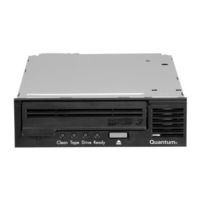
Figure 1 Internal LTO-4 (Model B) Half-Height Tape Drive
18
Features
19
Table 1 Performance Features and Capabilities
19
Installation Procedures
21
Chapter 2 Installation Procedures
21
Before Installing the LTO-4 (Model B) Half-Height Tape Drive
22
Handling Precautions and Installation Guidelines
22
Preinstallation Requirements
23
Unpacking and Inspecting the Drive
24
Installing the Internal LTO-4 (Model B) Half-Height Tape Drive
24
Configuring the Internal Parallel SCSI Tape Drive
25
Figure 2 Internal Parallel SCSI ID Configuration Jumper Pins
26
Figure 3 Internal Parallel SCSI Bus Termination Examples
27
Mounting the Internal Tape Drive
28
Figure 4 Acceptable Mounting Orientation
28
Connecting the Internal Drive Interface and DC Power Cables
29
Figure 5 Internal Tape Drive Mounting Hole Locations
29
Figure 6 Internal SCSI Drive Interface and DC Power Connectors
30
Figure 7 Internal SAS Drive Interface and DC Power Connectors
30
Restarting the Internal Tape Drive System
31
Installing the Tabletop LTO-4 (Model B) Half-Height Tape Drive
32
Configuring the Tabletop Parallel SCSI Tape Drive
33
Connecting the Tabletop Drive Interface and AC Power
34
Cables
34
Figure 8 Tabletop Parallel SCSI ID Selector Switch
34
Figure 9 Tabletop SCSI Interface and Power Cable Connectors
35
Figure 10 Tabletop SAS Interface and Power Cable Connectors
36
Restarting the Tabletop Drive System
38
Figure 11 Tabletop Parallel SCSI Bus Termination Examples
38
Installing the LTO Driver Software
39
Registering the LTO-4 (Model B) Half-Height Tape Drive
39
Chapter 3 Operation
41
Operation
41
Understanding the Front Panel Display
41
Figure 12 Front Panel Display
42
Table 2 Front Panel Display LED Blink Codes
44
Using LTO Tape Cartridges
46
Loading a Tape Cartridge
46
Unloading a Tape Cartridge
46
Write Protecting a Tape Cartridge
47
Figure 13 Ultrium Tape Cartridge Write-Protect Switch
47
Tape Cartridge Care and Maintenance
48
Cleaning the Tape Drive
49
Performing an Emergency Cartridge Eject
50
Chapter 4 Theory
51
Theory
51
Track Layout
51
Figure 14 Layout of the Tracks on LTO Ultrium Tapes
52
Data Buffer
53
Data Integrity
53
Error-Correction Code (ECC)
54
Servo-Tracking Faults
55
Recording Method
53
Data Compression
55
Data Compression Considerations
56
Intelligent Data Compression
57
Chapter 5 Specifications
59
Physical Specifications
60
Table 3 Physical Specifications
60
Physical Specifications
59
Specifications
59
Table 7 Environmental Requirements
59
Figure 16 LTO-4 (Model B) Half-Height Drive Dimensions (Side)
61
Power Specifications
61
Table 4 Voltage and Current Specifications
61
Table 5 Power Dissipation
62
Drive Performance Specifications
63
Table 6 Drive Performance Specifications
63
Environmental Requirements
64
Injected Noise Specifications
65
Reliability Specifications
65
Mean Time between Failures
66
Mean Time to Replace
66
Table 8 Reliability Specifications
66
LTO Cartridge Specifications
67
Environmental Considerations
67
Table 9 Environmental Tolerances
67
Cartridge Memory
68
Cartridge Reliability
68
Chapter 6 Troubleshooting Guide
69
Using a Serial-Attached SCSI Host Bus Adapter
70
HBA Preinstallation Checks
70
Installation Best Practices
69
Following SCSI Best Practices
69
Troubleshooting Guide
69
Troubleshooting Suggestions
70
Computer Does Not Start
70
Computer Hardware Does Not Recognize the Tape Drive
71
Computer Software Does Not Recognized the Tape Drive
72
Slow Backup Operations
73
Failed Operations Tapealert Messages
76
Figure 17 Front Panel Display
82
Understanding LED Sequences
82
Table 10 Tape Drive LED Sequences
83
Appendix A Installation Checklists
87
Internal LTO-4 (Model B) Half-Height Tape Drive Quick Start
87
Tabletop LTO-4 (Model B) Half-Height Tape Drive Quick Start
88
Disposal of Electrical & Electronic Equipment
91
Appendix B Appendix C Regulatory Compliances
93
Safety Compliances
93
Electromagnetic Compatibility (EMC) Compliances
94
Quantum LTO-4 (Model B) User Manual (86 pages)
half-height tape drive
Brand:
Quantum
| Category:
Storage
| Size: 1 MB
Table of Contents
Copyright Statement
2
Trademark Statement
2
Table of Contents
3
Technical Publications
12
Chapter 1 Introduction
14
Overview
14
Drive Models
15
Internal
15
Tabletop
15
Figure 1 Internal LTO-4 Half-Height Tape Drive
15
Table 1 Performance Features and Capabilities
16
Features
16
Chapter 2 Installation Procedures
18
Before Installing the LTO-4 Half-Height Tape Drive
19
Handling Precautions and Installation Guidelines
19
Preinstallation Requirements
20
Unpacking and Inspecting the Drive
20
Installing the Internal LTO-4 Half-Height Tape Drive
21
Mounting the Internal Tape Drive
22
Figure 2 Acceptable Mounting Orientation
22
Connecting the Internal Drive Interface and DC Power Cables
23
Figure 3 Internal Tape Drive Mounting Holes
23
Chapter 2 Installation Procedures Installing the Internal LTO-4 Half-Height Tape Drive
23
Restarting the Internal Tape Drive System
24
Figure 4 Internal Drive Interface and Power Connectors
24
Chapter 2 Installation Procedures Installing the Tabletop LTO-4 Half-Height Tape Drive
25
Installing the Tabletop LTO-4 Half-Height Tape Drive
25
Connecting the Tabletop Drive Interface and AC Power Cables
25
Restarting the Tabletop Drive System
26
Figure 5 Tabletop Drive Interface and Power Cable Connectors
26
Installing the LTO Driver Software
27
Registering the LTO-4 Half-Height Tape Drive
27
Chapter 2 Installation Procedures Installing the LTO Driver Software
27
Chapter 3 Operation
28
Understanding the Front Panel Display
28
Table 2 Front Panel Display Indications
29
Figure 6 Front Panel Display
29
Using LTO Tape Cartridges
31
Loading a Tape Cartridge
31
Unloading a Tape Cartridge
31
Write Protecting a Tape Cartridge
31
Tape Cartridge Care and Maintenance
32
Figure 7 Ultrium Tape Cartridge Write-Protect Switch
32
Cleaning the Tape Drive
33
Performing an Emergency Cartridge Eject
35
Chapter 3 Operation Performing an Emergency Cartridge Eject
35
Chapter 4 Theory
36
Theory Track Layout
36
Figure 8 Layout of the Tracks on LTO Ultrium Tapes
37
Recording Method
38
Data Buffer
38
Data Integrity
38
Chapter 4 Theory Recording Method
38
Chapter 4 Theory Data Integrity
39
Error-Correction Code (ECC)
39
Servo-Tracking Faults
40
Data Compression
40
Chapter 4 Theory Data Compression
40
Data Compression Considerations
41
Intelligent Data Compression
42
Chapter 5 Specifications
44
Specifications
44
Physical Specifications
45
Chapter 5 Specifications Physical Specifications
45
Figure 9 LTO-4 Half-Height Tape Drive Dimensions
46
Table 4 Voltage and Current Specifications
47
Table 5 Power Dissipation
47
Power Specifications
47
Chapter 5 Specifications Power Specifications
47
Drive Performance Specifications
48
Environmental Requirements
50
Chapter 5 Specifications Environmental Requirements
50
Injected Noise Specifications
51
Reliability Specifications
51
Chapter 5 Specifications Injected Noise Specifications
51
Mean Time between Failures
52
Mean Time to Replace
52
LTO Cartridge Specifications
52
Environmental Considerations
52
Chapter 5 Specifications LTO Cartridge Specifications
52
Table 9 Environmental Tolerances
53
Cartridge Memory
53
Cartridge Reliability
53
Chapter 6 Troubleshooting Guide
54
Installation Best Practices
54
Following SCSI Best Practices
54
Using a Serial-Attached SCSI Host Bus Adapter
54
HBA Preinstallation Checks
55
Troubleshooting Suggestions
55
Computer Does Not Start
55
Computer Hardware Does Not Recognize the Tape Drive
56
Computer Software Does Not Recognized the Tape Drive
61
Drive Does Not Load the Tape Cartridge
63
Drive Does Not Eject the Tape Cartridge
65
Slow Backup Operations
67
Failed Operations Tapealert Messages
69
Appendix A Installation Checklists
76
Internal LTO-4 Half-Height Tape Drive Quick Start
77
Tabletop LTO-4 Half-Height Tape Drive Quick Start
78
Appendix B Disposal of Electrical & Electronic Equipment
79
Appendix C Regulatory Compliances
80
Safety Compliances
81
Electromagnetic Compatibility (EMC) Compliances
82
Advertisement
Quantum LTO-4 (Model B) Reference (32 pages)
installation into a linux os
Brand:
Quantum
| Category:
Storage
| Size: 0 MB
Table of Contents
Table of Contents
1
January
5
Purpose
5
Scope
5
Conventions Used in this Guide
5
Document Number
6
Reference Documents
6
Setting up Communication with the Tape Drives
7
Before Installing the Tape Drive
7
Installing the Tape Drive
8
Verifying the St Module Is Loaded
8
Verifying Communication with the Tape Drives
9
Displaying the Kernel Initialization Information
9
Reviewing the Kernel Initialization Information
9
Obtaining Device Information Using /Proc/Scsi/Scsi
10
Identifying the Tape Devices
10
What to Do if Device Information Is Missing
10
What Is the /Proc File System
10
Viewing /Proc Files
10
Accessing Devices Using /Dev/St* Device Nodes
11
Generating a List of Device Files
11
Reviewing the List of Device Files
11
Auto Rewind
12
What to Do if a Device Node Is Missing
12
Interpreting the Device Node File Listing
13
Identifying Device Nodes
14
Identifying Device Modes
15
Creating Device Nodes
15
Creating Auto-Rewind Device Nodes
16
Creating No-Rewind Device Nodes
16
Mt-St Linux RPM Package
17
Mt Tape Device Tool
17
Verifying Mt-St Is Installed
17
Installing Mt-St
17
Stinit and Stinit.def
18
Tape Device and Parameter Definitions
18
Identifying Tape Devices and Parameters
19
Common Tape Device Keywords
19
Common Parameter Keywords
19
Mtx Tape Library Tool
20
Verifying Mtx Is Installed
20
Installing Mtx
21
Appendix A - Tape Drive and Cartridge Compatibility
22
Tape Drive and Cartridge Compatibility - DLT
22
Tape Drive and Cartridge Compatibility - SDLT
23
Tape Drive and Cartridge Compatibility - VS
23
Tape Drive and Cartridge Compatibility - LTO
24
Tape Drive and Cartridge Compatibility - DDS/DAT
24
Appendix B - Linux Reference Documentation
25
Appendix C - Sample Stinit.def Definitions File
26
Recommendations
26
Sample File
26
Appendix D - Troubleshooting
31
Quantum LTO-4 (Model B) Installation Manual (24 pages)
1U Rackmount Enclosure
Brand:
Quantum
| Category:
Storage
| Size: 2 MB
Table of Contents
Table of Contents
1
Connecting the Drive Interface and Power Cables
2
Installing a Second Tape Drive or Replacing a Tape Drive
4
Preinstallation Requirements
4
Installation Procedure
4
SCSI Cable Configurations
12
Installing the 1U Rackmount Enclosure in a Rack
15
Tools Required
15
Installation Procedure
15
Completing the Installation
22
Class a Device Declarations
24
Quantum LTO-4 (Model B) Installation Manual (24 pages)
1U Rackmount Enclosure
Brand:
Quantum
| Category:
Enclosure
| Size: 5 MB
Table of Contents
Table of Contents
1
Connecting the Drive Interface and Power Cables
2
Installing a Second Tape Drive or Replacing a Tape Drive
4
Preinstallation Requirements
4
Installation Procedure
4
SCSI Cable Configurations
12
Installing the 1U Rackmount Enclosure in a Rack
15
Tools Required
15
Installation Procedure
15
Completing the Installation
22
Class a Device Declarations
24
Quantum LTO-4 (Model B) Quick Start Manual (24 pages)
Quantum 1U Rackmount Enclosure Quick Start Guide
Brand:
Quantum
| Category:
Computer Accessories
| Size: 2 MB
Table of Contents
Table of Contents
1
Connecting the Drive Interface and Power Cables
2
Installing a Second Tape Drive or Replacing a Tape Drive
4
Preinstallation Requirements
4
Installation Procedure
4
SCSI Cable Configurations
12
Installing the 1U Rackmount Enclosure in a Rack
15
Tools Required
15
Installation Procedure
15
Completing the Installation
22
Class a Device Declarations
24
Quantum LTO-4 (Model B) Quick Start Manual (11 pages)
Half-Height Tape Drive
Brand:
Quantum
| Category:
Storage
| Size: 0 MB
Table of Contents
Before Installing the LTO-4 Half-Height Tape Drive
2
Installing the Internal LTO-4 Half-Height Tape Drive
3
Installing the Tabletop LTO-4 Half-Height Tape Drive
6
Installing the Lto Driver Software
7
Safety Compliances
8
Registering the LTO-4 Half-Height Tape Drive
8
Electromagnetic Compatibility (EMC) Compliances
9
Advertisement
Related Products
Quantum LTO 4
Quantum LTO 3A
Quantum ValueLoader LTO-2
Quantum LTO-6
Quantum LTO 3
Quantum LTO Ultrium
Quantum LTO-9 HH SAS
Quantum LTO-5 HH SAS C
Quantum LTO-3
Quantum LTO-8 HH SAS
Quantum Categories
Storage
Wheelchair
Network Hardware
Wireless Access Point
Controller
More Quantum Manuals
Login
Sign In
OR
Sign in with Facebook
Sign in with Google
Upload manual
Upload from disk
Upload from URL