Sign In
Upload
Manuals
Brands
Photon Focus Manuals
Digital Camera
MV4 Series
Photon Focus MV4 Series Manuals
Manuals and User Guides for Photon Focus MV4 Series. We have
3
Photon Focus MV4 Series manuals available for free PDF download: User Manual
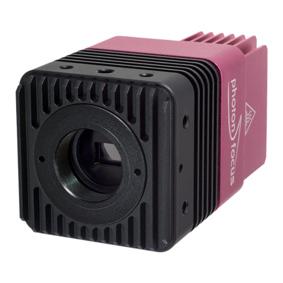
Photon Focus MV4 Series User Manual (151 pages)
CMOS camera series with GigE Interface
Brand:
Photon Focus
| Category:
Digital Camera
| Size: 14 MB
Table of Contents
Table of Contents
3
Preface
9
Important Notice
9
About Photonfocus
10
Contact
10
Sales Offices
10
Further Information
10
Legend
11
Introduction
13
Camera Naming Convention
13
Camera List
13
Product Specification 3.1 Introduction
15
Feature Overview
18
Technical Specification
19
Absolute Maximum Ratings
22
Electrical Characteristics
22
Spectral Response
24
Image Acquisition
25
Overview
25
Vocabulary
25
Structure
25
Image Acquisition, Frame and Exposure Control Parameters
26
Image Acquisition, Frame and Exposure Trigger
27
Image Acquisition, Frame and Exposure Status
27
Acquisition Control
28
Acquisition Start and Stop Commands, Acquisition Mode and Acquisition Frame Count
28
Acquisition Frame Rate and Acquisition Frame Rate Enable
28
Acquisition Start Trigger
29
Acquisition End Trigger
30
Acquisition Control Output Signals
30
Frame Control
31
Frame Start Trigger
31
Frame Burst Start Trigger
31
Frame Burst End Trigger
32
Frame Control Output Signals
33
Exposure Control
34
Exposure Mode
34
Exposure Start Trigger
34
Exposure End Trigger
34
Exposure Control Output Signals
35
Overlapped Image Acquisition Timing
36
Acquisition-, Frame- and Exposure-Trigger Configuration
38
Trigger Source Selection
38
Trigger Software
39
Trigger Mode
39
Trigger Activation
39
Trigger Divider
40
Trigger Delay
40
Software Signal Pulse and User Output
41
Counter & Timer
43
Counter
43
Counter Usage
43
Counter Status
44
Counter Active, -Start and -End Signal
44
Counter Reset
44
Counter Event Source
45
Counter Trigger Source
46
Counter Reset Source
47
Timer
49
Timer Usage
49
Timer Status
49
Timer Active, -Start and -End Signal
50
Timer Reset
50
Timer Trigger Source
50
Encoder
53
Encoder Usage
53
Encoder Trigger Output
54
Encoder Status
54
Encoder Reset Source
55
O Control
57
Input Signal Path
57
Output Signal Path
58
Action Control
59
Action Command Usage
59
Action Control Output
60
Image Format Control
61
Region of Interest (ROI)
61
Multiple Regions of Interest
61
Pixel Format
65
Decimation (Monochrome Cameras)
65
High Dynamic Range Mode (HDR)
69
Multiple Slope Mode (High Dynamic Range)
69
Frame Rate
71
Maximum Frame Rate
71
Pixel Data Processing
73
Overview
73
Bad Pixel Correction
74
Enable / Disable the Bad Pixel Correction
74
Calibration of the Bad Pixel Correction
74
Storing the Calibration in Permanent Memory
75
Column FPN Correction
75
Enable / Disable the Column FPN Correction
75
Calibration of the Column FPN Correction
75
Storing the Calibration in Permanent Memory
76
Gain and Offset
76
Grey Level Transformation (LUT)
77
Gain
77
Gamma
79
User-Defined Look-Up Table
80
Region LUT and LUT Enable
80
Binning
83
Description
83
Camera Settings
83
Dual Crosshairs
85
Test Images
87
Ramp
87
Lfsr
87
Troubleshooting Using the LFSR
87
Status Line and Image Information
89
Image Average Value
89
Status Line Format
89
Camera Type Codes
91
Double Rate (DR Cameras Only)
92
Frame Combine
92
1Frame Combine Timeout
92
Precautions
95
Important Notice
95
Hardware Interface
99
Absolute Maximum Ratings
99
Electrical Characteristics
99
Gige Camera Connector
101
Power Supply / Power over Ethernet (Poe)
103
Status Indicator (Gige Cameras)
104
I/O Connector
105
Overview
105
Input Fault Detection
107
Single-Ended Line Input
107
Encoder Interface
109
Single-Ended Line Output
111
Master / Slave Camera Connection
112
I/O Wiring
113
Separate Grounds
113
Common Grounds with Star Wiring
114
Mechanical Considerations
117
Mechanical Interface
117
MV4-D1280-L01 with Gige Interface
118
MV4-D1952-L01 with Gige Interface
120
C-Mount M42 Adapter
123
Adjusting the Back Focus
124
Optical Interface
124
Cleaning the Sensor
124
Troubleshooting
127
No Images Can be Acquired
127
No Acquisition Due to no Triggers
127
Standards Compliance
129
Directives and General Standards
129
Country-Specific Information
129
For Customers in the USA
129
For Customers in Canada
130
Pour Utilisateurs Au Canada
130
Life Support Applications
130
Warranty
131
Warranty Terms
131
Warranty Claim
131
Breach of Warranty
131
Support and Repair
133
Technical Support
133
Repair and Obtaining an RMA Number
133
Temporal Abandoning and Scrapping
133
References
135
A Pinouts
137
I/O Connector
137
Gige Connector
139
B Camera Timing
141
Timed Exposure Mode Camera Timing
141
C Use Cases
143
Acquisition
143
Camera Runs in "Free-Running" Mode
143
Camera Runs in "Constant Frame Rate" Mode
143
Camera Runs in Triggered Mode
143
Camera Runs in Burst Triggered Mode
144
Trigger Controlled Exposure Mode
145
Timer
145
Strobe Signal Output
145
Counter
146
Counter Reset
146
Image Counter
146
Real Time Counter
146
Missed Trigger Counter
147
Look-Up Table (LUT)
147
Overview
147
Full ROI LUT
147
Region LUT
148
User Defined LUT Settings
148
Predefined LUT Settings
148
Encoder
148
Configuration of the Encoder AB Signals
149
Configuration of the Encoder Z Signal
149
Configuration of the Encoder ALARM Signal
149
D Document Revision History
151
Advertisement
Photon Focus MV4 Series User Manual (143 pages)
Brand:
Photon Focus
| Category:
Digital Camera
| Size: 7 MB
Table of Contents
Table of Contents
3
Preface
9
Important Notice
9
About Photonfocus
10
Contact
10
Sales Offices
10
Further Information
10
Legend
11
Introduction
13
Camera Naming Convention
13
Camera List
13
Product Specification 3.1 Introduction
15
Feature Overview
17
Technical Specification
18
Absolute Maximum Ratings
20
Electrical Characteristics
20
Spectral Response
22
Image Acquisition
23
Overview
23
Vocabulary
23
Structure
23
Image Acquisition, Frame and Exposure Control Parameters
24
Image Acquisition, Frame and Exposure Trigger
25
Image Acquisition, Frame and Exposure Status
25
Acquisition Control
26
Acquisition Start and Stop Commands, Acquisition Mode and Acquisition Frame Count
26
Acquisition Frame Rate and Acquisition Frame Rate Enable
26
Acquisition Start Trigger
27
Acquisition End Trigger
28
Acquisition Control Output Signals
28
Frame Control
29
Frame Start Trigger
29
Frame Burst Start Trigger
29
Frame Burst End Trigger
30
Frame Control Output Signals
31
Exposure Control
32
Exposure Mode
32
Exposure Start Trigger
32
Exposure End Trigger
32
Exposure Control Output Signals
33
Overlapped Image Acquisition Timing
34
Acquisition-, Frame- and Exposure-Trigger Configuration
36
Trigger Source Selection
36
Trigger Software
37
Trigger Mode
37
Trigger Activation
37
Trigger Divider
38
Trigger Delay
38
Software Signal Pulse and User Output
39
Exposure Control
41
Triggercontrolled Exposure
41
Counter & Timer
43
Counter
43
Counter Usage
43
Counter Status
44
Counter Active, -Start and -End Signal
44
Counter Reset
44
Counter Event Source
45
Counter Trigger Source
46
Counter Reset Source
47
Timer
49
Timer Usage
49
Timer Status
49
Timer Active, -Start and -End Signal
50
Timer Reset
50
Timer Trigger Source
50
Encoder
53
Encoder Usage
53
Encoder Trigger Output
54
Encoder Status
54
Encoder Reset Source
55
O Control
57
Input Signal Path
57
Output Signal Path
58
Action Control
59
Action Command Usage
59
Action Control Output
60
Image Format Control
61
Region of Interest (ROI)
61
Pixel Format
61
Decimation (Monochrome Cameras)
61
Frame Rate
65
Maximum Frame Rate
65
Pixel Data Processing 12.1 Overview
67
Image Correction
68
Overview
68
Offset Correction
69
Gain Correction
70
Defect Pixel Correction
71
Corrected Image
73
Correction Ranges
73
Gain and Offset
74
Grey Level Transformation (LUT)
74
Gain
75
Gamma
77
User-Defined Look-Up Table
78
Region LUT and LUT Enable
78
Binning
81
Description
81
Camera Settings
81
Dual Crosshairs
83
Test Images
85
Ramp
85
Lfsr
85
Troubleshooting Using the LFSR
85
Status Line and Image Information
87
Image Average Value
87
Status Line Format
87
Camera Type Codes
89
Frame Combine
90
Frame Combine Timeout
90
Precautions
93
Important Notice
93
Hardware Interface
97
Absolute Maximum Ratings
97
Electrical Characteristics
97
Gige Camera Connector
99
Power Supply / Power over Ethernet (Poe)
101
Status Indicator (Gige Cameras)
102
I/O Connector
103
Overview
103
Input Fault Detection
105
Single-Ended Line Input
105
Encoder Interface
107
Single-Ended Line Output
109
Master / Slave Camera Connection
110
I/O Wiring
111
Separate Grounds
111
Common Grounds with Star Wiring
112
Mechanical Considerations
115
Mechanical Interface
115
Cameras with Gige Interface
115
Adjusting the Back Focus
116
Optical Interface
116
Cleaning the Sensor
116
Troubleshooting
119
No Images Can be Acquired
119
No Acquisition Due to no Triggers
119
Standards Compliance
121
Directives and General Standards
121
Country-Specific Information
121
For Customers in the USA
121
For Customers in Canada
122
Pour Utilisateurs au Canada
122
Life Support Applications
122
Warranty
123
Warranty Terms
123
Warranty Claim
123
Breach of Warranty
123
Support and Repair
125
Technical Support
125
Repair and Obtaining an RMA Number
125
Temporal Abandoning and Scrapping
125
References
127
A Pinouts
129
I/O Connector
129
Gige Connector
131
B Camera Timing
133
Timed Exposure Mode Camera Timing
133
C Use Cases
135
Acquisition
135
Camera Runs in "Free-Running" Mode
135
Camera Runs in "Constant Frame Rate" Mode
135
Camera Runs in Triggered Mode
135
Camera Runs in Burst Triggered Mode
136
Trigger Controlled Exposure Mode
137
Timer
137
Strobe Signal Output
137
Counter
138
Counter Reset
138
Image Counter
138
Real Time Counter
138
Missed Trigger Counter
139
Look-Up Table (LUT)
139
Overview
139
Full ROI LUT
139
Region LUT
140
User Defined LUT Settings
140
Predefined LUT Settings
140
Encoder
140
Configuration of the Encoder AB Signals
141
Configuration of the Encoder Z Signal
141
Configuration of the Encoder ALARM Signal
141
Calibration of the FPN Correction
141
D Document Revision History
143
Photon Focus MV4 Series User Manual (141 pages)
Brand:
Photon Focus
| Category:
Digital Camera
| Size: 11 MB
Table of Contents
Table of Contents
3
Preface
9
Important Notice
9
About Photonfocus
10
Contact
10
Sales Offices
10
Further Information
10
Legend
11
Introduction
13
Camera Naming Convention
13
Camera List
13
Product Specification 3.1 Introduction
15
Feature Overview
17
Technical Specification
18
Absolute Maximum Ratings
21
Electrical Characteristics
21
Spectral Response
23
Image Acquisition
25
Overview
25
Vocabulary
25
Structure
25
Image Acquisition, Frame and Exposure Control Parameters
26
Image Acquisition, Frame and Exposure Trigger
27
Image Acquisition, Frame and Exposure Status
27
Acquisition Control
28
Acquisition Start and Stop Commands, Acquisition Mode and Acquisition Frame Count
28
Acquisition Frame Rate and Acquisition Frame Rate Enable
28
Acquisition Start Trigger
29
Acquisition End Trigger
30
Acquisition Control Output Signals
30
Frame Control
31
Frame Start Trigger
31
Frame Burst Start Trigger
31
Frame Burst End Trigger
32
Frame Control Output Signals
33
Exposure Control
34
Exposure Mode
34
Exposure Start Trigger
34
Exposure End Trigger
34
Exposure Control Output Signals
35
Overlapped Image Acquisition Timing
36
Acquisition-, Frame- and Exposure-Trigger Configuration
38
Trigger Source Selection
38
Trigger Software
39
Trigger Mode
39
Trigger Activation
39
Trigger Divider
40
Trigger Delay
40
Software Signal Pulse and User Output
41
Counter & Timer
43
Counter
43
Counter Usage
43
Counter Status
44
Counter Active, -Start and -End Signal
44
Counter Reset
44
Counter Event Source
45
Counter Trigger Source
46
Counter Reset Source
47
Timer
49
Timer Usage
49
Timer Status
49
Timer Active, -Start and -End Signal
50
Timer Reset
50
Timer Trigger Source
50
Encoder
53
Encoder Usage
53
Encoder Trigger Output
54
Encoder Status
54
Encoder Reset Source
55
O Control
57
Input Signal Path
57
Output Signal Path
58
Action Control
59
Action Command Usage
59
Action Control Output
60
Image Format Control
61
Region of Interest (ROI)
61
Multiple Regions of Interest
61
Pixel Format
65
Decimation (Monochrome Cameras)
65
Frame Rate
69
Maximum Frame Rate
69
Pixel Data Processing
71
Overview
71
Column Group Correction
72
Enable / Disable the Column FPN Correction
72
Calibration of the Column FPN Correction
72
Bad Pixel Correction
72
Enable / Disable the Bad Pixel Correction
72
Calibration of the Bad Pixel Correction
72
Storing the Calibration in Permanent Memory
73
Gain and Offset
73
Grey Level Transformation (LUT)
74
Gain
74
Gamma
76
User-Defined Look-Up Table
77
Region LUT and LUT Enable
77
Binning
80
Description
80
Camera Settings
80
Dual Crosshairs
82
Test Images
84
Ramp
84
Lfsr
84
Troubleshooting Using the LFSR
84
Status Line and Image Information
86
Image Average Value
86
Status Line Format
86
Camera Type Codes
88
Frame Combine
89
1Frame Combine Timeout
89
Precautions
91
Important Notice
91
Hardware Interface
95
Absolute Maximum Ratings
95
Electrical Characteristics
95
MV4 Gige Camera Connector
97
MV8 Gige Camera Connector
99
Power Supply / Power over Ethernet (Poe)
100
Status Indicator (Gige Cameras)
101
I/O Connector
102
Overview
102
Input Fault Detection
103
Single-Ended Line Input
104
Encoder Interface
105
Single-Ended Line Output
107
Master / Slave Camera Connection
108
I/O Wiring
109
Separate Grounds
109
Common Grounds with Star Wiring
110
Mechanical Considerations
113
Mechanical Interface
113
Cameras with Gige Interface
113
Optical Interface
115
Cleaning the Sensor
115
Troubleshooting
117
No Images Can be Acquired
117
No Acquisition Due to no Triggers
117
Standards Compliance
119
Directives and General Standards
119
Country-Specific Information
119
For Customers in the USA
119
For Customers in Canada
120
Pour Utilisateurs au Canada
120
Life Support Applications
120
Warranty
121
Warranty Terms
121
Warranty Claim
121
Breach of Warranty
121
Support and Repair
123
Technical Support
123
Repair and Obtaining an RMA Number
123
Temporal Abandoning and Scrapping
123
References
125
A Pinouts
127
I/O Connector
127
Gige Connector
129
B Camera Timing
131
Timed Exposure Mode Camera Timing
131
C Use Cases
133
Acquisition
133
Camera Runs in "Free-Running" Mode
133
Camera Runs in "Constant Frame Rate" Mode
133
Camera Runs in Triggered Mode
133
Camera Runs in Burst Triggered Mode
134
Trigger Controlled Exposure Mode
135
Timer
135
Strobe Signal Output
135
Counter
136
Counter Reset
136
Image Counter
136
Real Time Counter
136
Missed Trigger Counter
137
Look-Up Table (LUT)
137
Overview
137
Full ROI LUT
137
Region LUT
138
User Defined LUT Settings
138
Predefined LUT Settings
138
Encoder
138
Configuration of the Encoder AB Signals
139
Configuration of the Encoder Z Signal
139
Configuration of the Encoder ALARM Signal
139
D Document Revision History
141
Advertisement
Advertisement
Related Products
Photon Focus MV4-D1280U-H01-G2
Photon Focus MV4-D1280U-H01-GT
Photon Focus MV4-D1280U-H01-FB
Photon Focus Luxima MV4-D1280-L01-G2
Photon Focus Luxima MV4-D1280-L01-GT
Photon Focus Luxima MV4-D1280-L01-FB
Photon Focus Luxima MV4-D1952-L01-G2
Photon Focus Luxima MV4-D1952-L01-GT
Photon Focus Luxima MV4-D1952-L01-FB
Photon Focus Gpixel MV4-D9344-G01-GT
Photon Focus Categories
Digital Camera
Security Camera
Color Camera
Scanner
Accessories
More Photon Focus Manuals
Login
Sign In
OR
Sign in with Facebook
Sign in with Google
Upload manual
Upload from disk
Upload from URL