Sign In
Upload
Manuals
Brands
Optimum Manuals
Lathe
OPTIturn TM 3310
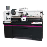
Optimum OPTIturn TM 3310 Center Lathe Manuals
Manuals and User Guides for Optimum OPTIturn TM 3310 Center Lathe. We have
1
Optimum OPTIturn TM 3310 Center Lathe manual available for free PDF download: Operating Manual
Optimum OPTIturn TM 3310 Operating Manual (102 pages)
Brand:
Optimum
| Category:
Lathe
| Size: 4 MB
Table of Contents
Table of Contents
2
1 Safety
6
Rating Plate
6
Machine Variants
6
Safety Instructions (Warning Notes)
7
Classification of Risks
7
Pictograms
8
Intended Use
8
Reasonably Foreseeable Misuses
9
Avoiding Misuse
9
Potential Dangers that Can be Caused by the Lathe
10
Qualification
10
Obligations of the Operating Company
10
User's Obligations
10
Additional Requirements Regarding the Qualification
11
Operator Positions
11
Safety Measures During Operation
11
Safety Devices
11
Emergency-Stop Button
12
Protective Cover of the Headstock
12
Lathe Chuck Protection with Position Switch
12
Protective Cover of Lead Screw
12
Safety Check
12
Personal Protective Equipment
13
Safety During Operation
13
Disconnecting and Securing the Lathe
14
Using Lifting Equipment
14
Mechanical Maintenance Work
14
Electronics
14
Inspection Deadlines
15
2 Technical Specification
16
Electrical Connection
16
Power
16
Work Areas
16
Work Area
16
Headstock
16
Slides
16
Feeds and Pitches
16
Tailstock
16
Dimensions
16
Emissions
17
Operating Material
17
3 Delivery, Interdepartmental Transport, Assembly and Commissioning
18
Notes on Transport, Installation, Commissioning
18
General Risks During Internal Transport
18
Delivery
19
Unpacking
19
Transport
19
Load Suspension Point
19
Gravity of the Machine
19
Lifting with a Forklift
20
Lifting by Crane
20
Installation Conditions
21
Foundation and Floor
21
Installation Plan
21
Assembly and Installation, Initial Operation
22
Anchor-Free Assembly
22
Installation with Levelling Discs
23
Installation with Vibration Dampers
23
Anchored Assembly
24
Aligning the Machine
25
Cleaning the Machine
25
Lubrication
25
One-Component Paint
25
Electric Three-Phase Connection
26
Warming up the Machine
26
4 Operation
27
Control and Indicating Elements
27
Safety
28
Overview of the Control Elements
28
Overview of Indicator Elements
29
Control Elements
30
Switching on the Machine
30
Switching on
30
Switching the Machine off
30
Resetting an Emergency Stop Condition
30
Power Failure, Restoring Readiness for Operation
31
Speed Setting
31
Fixing the Lathe Saddle
31
Changing the Feed Rate
31
Selector Switch
31
Changing the Change Gears
32
Crossfeed, Longitudinal Feed
32
Tool Holder
33
Lathe Spindle Fixture
33
Fasten Workpiece Holder
34
Adjusting the Camlock Bolts to the Workpiece Holder
35
Clamping a Workpiece into the Three Jaw Chuck
35
Turning Tapers
36
Taper Turning with the Top Slide
36
Taper Turning with the Tailstock
36
Turning of Cones with High Precision
37
Standard Values for Cutting Data When Turning
39
Cutting Speed Table
40
Terms for the Rotating Tool
41
Cutting Edge Geometry for Turning Tools
42
Types of Cutting Form Levels
42
Tapping of External and Internal Threads
44
Thread Types
45
Metric Threads (60° Flank Angle)
46
British Thread (55° Flank Angle)
48
Indexable Inserts
49
Examples for Thread Cutting
50
General Operating Instructions
52
Clamping Long Workpieces
52
Mounting of Rests
52
Tailstock
52
Cross-Adjustment of the Tailstock
53
General Operating Instructions
53
Longitudinal Turning
53
Face Turning and Recessing
54
Turning Short Tapers with the Top Slide
54
Thread Cutting
55
Cooling Lubricant
56
5 Cutting Speeds
57
Selecting the Cutting Speed
57
Influences on the Cutting Speed
57
Example for the Determination of the Required Speed on Your Lathe
57
6 Maintenance
59
Safety
59
Preparation
59
Restarting
59
Inspection and Maintenance
60
Recommended Wearing Parts
65
Lubricating and Cleaning the Lathe Chuck
65
Repair
66
Customer Service Technician
66
7 Ersatzteile - Spare Parts
67
Ersatzteilbestellung - Ordering Spare Parts
67
Hotline Ersatzteile - Spare Parts Hotline
67
Service Hotline
67
Elektrische Ersatzteile - Electrical Spare Parts
67
Schaltplan - Wiring Diagram
67
Spindelgetriebe - Headstock
68
Vorschubgetriebe - Feed Gear
73
Vorschubgetriebe - Feed Gear
74
Vorschubgetriebe - Feed Gear
75
Schlosskasten - Apron
77
Schlosskasten - Apron
78
Planschlitten, Bettschlitten - Cross Slide, Bed Slide
80
Oberschlitten - Top Slide
82
Maschinenbett - Machine Bed
83
Maschinenbett - Machine Bed
84
Reitstock - Tailstock
86
Drehfutterschutz - Lathe Chuck Protection
87
Späneschutz - Chip Cover
88
Schaltplan - Wiring Diagram
89
8 Malfunctions
94
9 Appendix 9.1 Copyright
96
9 Appendix
96
Change Information Manual
96
Terminology/Glossary
96
Liability Claims/Warranty
97
Dismantling, Disassembling, Packing and Loading
98
Decommissioning
99
Dismantling
99
Disassembly
99
Packing and Loading
99
Storage
98
Disposal of New Device Packaging
99
Advertisement
Advertisement
Related Products
Optimum OPTiturn TM 4010
Optimum OPTIturn TU 3008V
Optimum Optiturn TU 2506
Optimum Optiturn TU 2506V
Optimum Optiturn TU 2807
Optimum Optiturn TU 2807V
Optimum OptiTurn TH 6620D
Optimum OPTIturn TX 6222
Optimum OPTI turn TU 3008G
Optimum OPTIturn TU 2506VB
Optimum Categories
Drill
Kettle
Kitchen Appliances
Blender
Power Tool
More Optimum Manuals
Login
Sign In
OR
Sign in with Facebook
Sign in with Google
Upload manual
Upload from disk
Upload from URL