Sign In
Upload
Manuals
Brands
Optimum Manuals
Drill
OPTimill MB 4
Optimum OPTimill MB 4 Manuals
Manuals and User Guides for Optimum OPTimill MB 4. We have
2
Optimum OPTimill MB 4 manuals available for free PDF download: Operating Manual
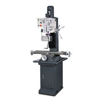
Optimum OPTimill MB 4 Operating Manual (110 pages)
Drilling-milling machine
Brand:
Optimum
| Category:
Industrial Equipment
| Size: 2 MB
Table of Contents
Table of Contents
2
Sicherheit
6
Typschild
6
Sicherheitshinweise (Warnhinweise)
7
Gefahren-Klassifizierung
7
Weitere Piktogramme
7
Bestimmungsgemäße Verwendung
8
Vernünftigerweise Vorhersehbare Fehlanwendung
9
Vermeidung von Fehlanwendungen
9
Gefahren die von der Bohr-Fräsmaschine Ausgehen können
10
Qualifikation des Personals
11
Zielgruppe
11
Autorisierte Personen
12
Pflichten des Betreibers
12
Pflichten des Bedieners
12
Zusätzliche Anforderungen an die Qualifikation
12
Bedienerpositionen
13
Sicherheitsmaßnahmen während des Betriebs
13
Sicherheitseinrichtungen
13
NOT-Halt Schalter
14
Schutzabdeckung
14
Hauptschalter Abschließbar
14
Trennende Schutzvorrichtung
15
Sicherheitsüberprüfung
15
Körperschutzmittel
16
Zu Ihrer Eigenen Sicherheit während des Betriebs
16
Abschalten und Sichern der Bohr-Fräsmaschine
16
Verwenden von Hebezeugen
17
Positionen der Symbole an der Bohr-Fräsmaschine
17
Elektrik
17
Prüffristen
18
Technische Daten
19
Stellplan
21
Anlieferung, Innerbetrieblicher Transport, Montage und Inbetriebnahme
23
Hinweise zu Transport, Aufstellung, Inbetriebnahme
23
Allgemeine Gefahren Beim Innerbetrieblichen Transport
23
Lieferumfang
24
Aufstellen und Montieren
24
Anforderungen an den Aufstellort
24
Lastanschlagstelle
24
3.3.3 Montieren
25
Erste Inbetriebnahme
26
Stromversorgung
26
Reinigen und Abschmieren
26
Getriebeöl Auffüllen
26
Bedienung
27
Bedien- und Anzeigeelemente
27
Sicherheit
28
Bohr-Fräsmaschine Einschalten
28
Drehzahltabelle 400V Drehstromantrieb
28
Drehzahltabelle 230V
28
Bohr-Fräsmaschine Ausschalten
29
Werkzeug Einsetzen
29
Einbau
29
Ausbau
29
Verwendung von Spannzangen
29
Spannen der Werkstücke
30
Veränderung des Drehzahlbereiches
30
Wahl der Drehzahl
30
Richtwerte für Schnittgeschwindigkeiten
30
Richtwerte für Drehzahlen mit HSS Schnellarbeitsstahl - Eco - Spiralbohrern
31
Manueller Pinolenvorschub mit dem Feinvorschub
32
Manueller Pinolenvorschub mit dem Pinolenhebel
32
4.10.1 Bohrtiefenanschlag
33
Bohr-/ Fräskopf Schwenken
33
Gewinde Schneiden
34
Instandhaltung
35
Sicherheit
35
Vorbereitung
35
Wiederinbetriebnahme
35
Inspektion und Wartung
36
Instandsetzung
39
Kundendiensttechniker
39
Störungen
40
Störungen an der Bohr-Fräsmaschine
40
Anhang
41
Urheberrecht
41
Terminologie/Glossar
41
Mangelhaftungsansprüche / Garantie
42
Lagerung
43
Entsorgungshinweis / Wiederverwertungsmöglichkeiten
43
Außerbetriebnehmen
43
Entsorgung der Neugeräte-Verpackung
44
Entsorgung des Altgerätes
44
Entsorgung der Elektrischen und Elektronischen Komponenten
44
Entsorgung der Schmiermittel und Kühlschmierstoffe
44
Entsorgung über Kommunale Sammelstellen
45
Produktbeobachtung
45
Änderungsinformationen Betriebsanleitung
45
Eg-Konformitätserklärung
46
Safety
48
Rating Plate
48
Safety Instructions (Warning Notes)
49
Classification of Hazards
49
Other Pictograms
49
Intended Use
50
Reasonably Foreseeable Misuses
51
Avoiding Misuse
51
Possible Dangers Caused by the Drilling- Milling Machine
52
Personnel Qualification
52
Target Group
52
Authorized Persons
53
Obligations of the Operating Company
53
User's Obligations
54
Additional Requirements Regarding Qualification
54
User Positions
54
Safety Measures During Operation
54
Safety Devices
55
Emergency Switching off Push Button
55
Protective Cover
56
Lockable Master Switch
56
Spindle Guard
57
Safety Check
57
Personal Protective Equipment
57
For Your Own Safety During Operation
58
Switching-Off and Securing the Drilling- Milling Machine
58
Using Lifting Equipment
58
Positions of the Symbols on the Drilling- Milling Machine
59
Electronics
59
Inspection Deadlines
59
Technical Specification
60
Installation Plan
62
Delivery, Interdepartmental Transport, Assembly and Commissioning
63
Notes on Transport, Installation, Commissioning
63
General Risks During Internal Transport
63
Scope of Delivery
64
Set-Up and Assembly
64
Installation Site Requirements
64
Load Suspension Point
64
3.3.3 Assembly
65
First Commissioning
66
Power Supply
66
Cleaning and Lubrication
66
Filling in Gear Oil
66
Operation
67
Control and Indicating Elements
67
Safety
68
Switching on the Drilling-Milling Machine
68
Speed Table 400V Three-Phase Drive
68
Speed Table 230V
68
Switching the Drilling-Milling Machine off
69
Inserting Tool
69
Installation
69
Removing
69
Use of Collets
69
Clamping the Workpieces
70
Changing the Speed Range
70
Selecting the Speed
70
Standard Values for Cutting Speeds
70
Standard Values for Speeds with HSS High Speed Steel - Eco - Twist Drills
71
Manual Quill Feed with the Fine Feed
72
Manual Quill Feed with the Quill Lever
72
4.10.1 Drill Depth Stop
72
Swivelling the Drill-Mill Head
73
Thread Tapping
74
Maintenance
75
Safety
75
Preparation
75
Restarting
75
Inspection and Maintenance
76
Repair
79
Customer Service Technician
79
Malfunctions
80
Milling Machine Malfunctions
80
Appendix 7.1 Copyright
81
Terminology/Glossary
81
Liability Claims/Warranty
82
Storage
83
Advice for Disposal / Options of Reuse
83
Decommissioning
83
Disposal of New Device Packaging
84
Disposal of the Old Device
84
Disposal of Electrical and Electronic Components
84
Disposal of Lubricants and Coolants
84
Disposal Via Municipal Collection Facilities
85
Change Information Operating Manual
85
Product Follow-Up
85
EC Declaration of Conformity
86
Ersatzteile - Spare Parts
87
Ersatzteilbestellung - Ordering Spare Parts
87
Hotline Ersatzteile - Spare Parts Hotline
87
Service Hotline
87
Ersatzteilzeichnungen - Spare Part Drawings
88
400V - Schaltplan Drehstromantrieb - Wiring Diagram Three-Phase Drive
103
Schaltplan Einphasiger Antrieb - Wiring Diagram One-Phase Drive
105
Advertisement
Optimum OPTimill MB 4 Operating Manual (70 pages)
Drilling- milling machine
Brand:
Optimum
| Category:
Drill
| Size: 2 MB
Table of Contents
Table of Contents
2
1 Safety
5
Rating Plates
5
Safety Instructions (Warning Notes)
6
Classification of Hazards
6
Other Pictograms
7
Intended Use
8
Reasonably Foreseeable Misuses
8
1.4.1 Avoiding Misuse
9
Possible Dangers Caused by the Drilling- Milling Machine
10
Personnel Qualification
10
Target Group
10
Authorized Persons
11
Obligations of the Operating Company
11
1.6.4 User's Obligations
12
Additional Requirements Regarding Qualification
12
User Positions
12
Safety Measures During Operation
12
Safety Devices
13
Emergency Switching off Push Button
13
Protective Cover
14
Lockable Master Switch
14
Separation Guard
14
Safety Check
14
Personal Protective Equipment
15
For Your Own Safety During Operation
15
Switching-Off and Securing the Drilling- Milling Machine
16
Using Lifting Equipment
16
Positions of the Symbols on the Drilling- Milling Machine
16
Electronics
16
Inspection Deadlines
17
2 Technical Specification
18
Installation Plan
20
3 Delivery, Interdepartmental Transport, Assembly and Commissioning
21
Notes on Transport, Installation, Commissioning
21
General Risks During Internal Transport
21
Scope of Delivery
22
Set-Up and Assembly
22
Installation Site Requirements
22
Load Suspension Point
22
3.3.3 Assembly
23
First Commissioning
24
Power Supply
24
Cleaning and Lubrication
24
Filling in Gear Oil
24
4 Operation
25
Control and Indicating Elements
25
Safety
26
Switching on the Drilling-Milling Machine
26
Switching off the Drilling-Milling Machine
26
Inserting the Tool
26
Installation
26
Removal
27
Use of Collets
27
Clamping the Workpieces
27
Changing the Speed Range
28
Speed Table Three-Phase Drive
28
Speed Table One-Phase Drive
29
Selecting the Speed
29
4.8.1 Standard Values for Cutting Speeds
30
Standard Values for Speeds with HSS - Eco - Twist Drills
31
Manual Spindle Sleeve Feed with the Fine Feed
31
Manual Spindle Sleeve Feed with the Spindle Sleeve Lever
32
4.10.1 Drill Depth Stop
32
Swivelling the Drill-Mill Head
32
Thread Tapping
33
5 Maintenance
34
Safety
34
Preparation
34
Restarting
34
Inspection and Maintenance
35
Repair
38
Customer Service Technician
38
6 Ersatzteile - Spare Parts
39
Ersatzteilbestellung - Ordering Spare Parts
39
Wichtiger Hinweis - Important Note
39
Hotline Ersatzteile - Spare Parts Hotline
39
Service Hotline
39
Fräskopf 1 von 6 - Milling Head 1 of 6
40
Fräskopf 2 von 6 - Milling Head 2 of 6
41
Fräskopf 3 von 6 - Milling Head 3 of 6
42
Fräskopf 4 von 6 - Milling Head 4 of 6
43
Fräskopf 5 von 6 - Milling Head 5 of 6
44
Fräskopf 6 von 6 - Milling Head 6 of 6
45
Fräsfutterschutz - Milling Chuck Protection
46
Schaltbox - Switch Box
47
Säule - Column
51
Kreuztisch - Cross Table
52
Maschinenschilder - Machine Labels
55
Schaltplan Drehstromantrieb - Wiring Diagram Three-Phase Drive
56
6.15.1 Teileliste Elektrik - Parts List Electrical Components - 400V
57
Schaltplan Einphasiger Antrieb - Wiring Diagram One-Phase Drive
58
6.16.1 Teileliste Elektrik - Parts List Electrical Components - 230V
59
7 Malfunctions
60
Milling Machine Malfunctions
60
8 Appendix 8.1 Copyright
61
8 Appendix
61
Terminology/Glossary
61
Liability Claims/Warranty
62
Advice for Disposal / Options of Reuse
63
Decommissioning
63
Disposal of New Device Packaging
64
Disposal of the Old Device
64
Disposal of Electrical and Electronic Components
64
Disposal of Lubricants and Coolants
64
Storage
63
Change Information Operating Manual
65
Disposal Via Municipal Collection Facilities
65
Product Follow-Up
65
Advertisement
Related Products
Optimum Optimill BF 30V
Optimum OPTImill BF 16 Vario
Optimum OPTImill MB 4PV
Optimum OPTImill MB 4P
Optimum MFE17L
Optimum OPTImill MH 50V
Optimum OPTimill MH 35V
Optimum Optimill MZ 4S
Optimum Optimill MH 20VL
Optimum M5
Optimum Categories
Drill
Kettle
Kitchen Appliances
Blender
Power Tool
More Optimum Manuals
Login
Sign In
OR
Sign in with Facebook
Sign in with Google
Upload manual
Upload from disk
Upload from URL