Sign In
Upload
Manuals
Brands
Onicon Manuals
Measuring Instruments
System-10 BTU Meter
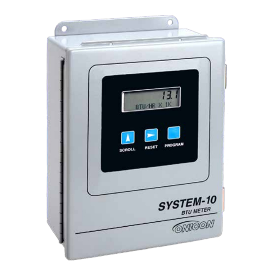
Onicon System-10 BTU Meter Tool Manuals
Manuals and User Guides for Onicon System-10 BTU Meter Tool. We have
8
Onicon System-10 BTU Meter Tool manuals available for free PDF download: Installation And Operation Manual, Installation Manual
Onicon System-10 BTU Meter Installation And Operation Manual (48 pages)
BTU Meter
Brand:
Onicon
| Category:
Measuring Instruments
| Size: 5 MB
Table of Contents
Heavy Duty Thermowell Assembly for Process Temperatures over 300°F
2
Table of Contents
3
Section 1.0 General Information
5
Purpose of this Manual
5
Typical System - 10 Btu Meter
5
Standard Features and Specifications
6
Model Numbering System
8
Additional Required Hardware
9
Working Environment
9
Serial Number
9
Section 2.0 Unpacking
10
Checking that You Have Received Everything
10
Documentation
10
Calibration Information
10
The System-10 BTU Meter
11
Temperature Sensors
11
Temperature Thermowells Installation Hardware
11
Flow Meter
11
Section 3.0 Installation
12
Site Selection
12
The System-10 BTU Meter
12
The Flow Meter
12
The Temperature Sensors
12
Mechanical Installation
13
Transmitter Details and Dimensions
13
Dry Tap Thermowells
14
Hot Tap Thermowells
14
Thermowell Installation
14
Flow Meter Installation
17
Temperature Sensor Installation
17
Electrical Installation
18
Input Power Requirements
18
Input Signal Connections
19
Input Signal Connections from Temperature Sensors
19
Input Signal Connections from F-1000 Series Flow Meters
20
Input Signal Connections from F-2000 Series (Loop Powered Versions) Flow Meters
21
Input Signal Connections from FT-3000 Series Flow Meters
22
Input Signal Connections from F-3500 Flow Meters
23
Input Signal Connections from FSM-3 Series Flow Meters
24
Input Signal Connections from F-4300 Flow Meters
25
Input Signal Connections from F-4600 Flow Meters
26
Input Signal Connections from F-4600 (LCD Versions) Flow Meters
27
Contact Closure Input for Flow Direction
28
Contact Closure Output for Energy Total(S) and Mode Status
28
Optional Isolated Analog Output(S)
29
Section 4.0 Start - up and Commissioning
30
Display and User Interface
30
Processor Start - up
30
Units and Multipliers
31
Analog Outputs
31
Selecting the Flow Meter Location & Enabling/Disabling Front Panel Reset
32
Commissioning
33
Commissioning Procedure
33
Commissioning Worksheet
35
Section 5.0 Diagnostics
36
Diagnostics
36
Diagnostic Lights
36
Flow Test Signals
36
Temperature Test Signals
36
Alarm Status Menu Page
37
Troubleshooting
38
Appendix A - Drawings
39
Outdoor Thermowell Assembly in Welded Pipe
40
System - 10 Btu Meter Mother Board
43
System - 10 Btu Meter Comm Board
44
System - 10 Btu Meter Power Supply Board
45
System - 10 Btu Meter Analog Output Board with 1 Analog Output
46
System - 10 Btu Meter Analog Outputs Board with 4 Analog Outputs
47
Advertisement
Onicon System-10 BTU Meter Installation And Operation Manual (67 pages)
BTU METER, Siemens P1-FLN Version
Brand:
Onicon
| Category:
Measuring Instruments
| Size: 4 MB
Table of Contents
Table of Contents
3
1 Introduction
5
Purpose of this Guide
5
Typical System-10 Btu Meter
5
Standard Features and Specifications
5
Additional Required Hardware
7
Working Environment
7
Warranty and Serial Number
7
2 Unpacking
8
Checking that You Have Received Everything
8
3 Installation
9
Site Selection
9
Mechanical Installation
10
Main Unit Installation
10
Thermowell Installation
11
Hot Tap Thermowells
11
Standard Thermowells
11
Temperature Sensor Installation
13
Flow Meter Installation
14
Electrical Installation
15
Input Power
15
Input Signal Connections
18
Input Signal Connections from Temperature Sensors
18
Input Signal Connections from F-2500 Meters
19
Input Signal Connections from Insertion Turbine
19
Input Signal Connections from F-2600 & F-2700
20
Input Signal Connections from F-3100 & F-3200
20
Input Signal Connections from F-3500 Meters
21
Input Signal Connections from FB-3500 Meters
21
Input Signal Connections from F-4200 Meters
22
Contact Closure Output for Energy Total(S) and Mode
23
Isolated Analog Output(S)
24
Network Signal Connections
25
Optional Isolated Digital Pulse Input (Di3)
26
4 System-10 Start-Up and Commissioning
29
Display and Keypad Operation
29
Processor Start-Up
29
Units and Multipliers
30
Analog Outputs
30
Entering a Network Address, Selecting the Flow Meter Location & Enabling / Disabling Front Panel Reset
31
Application Number
32
System-10-P1 Point Database
33
Commissioning
35
Onicon System-10 BTU Meter Installation And Operation Manual (58 pages)
BTU METER
Brand:
Onicon
| Category:
Measuring Instruments
| Size: 5 MB
Table of Contents
Safety Information
2
Table of Contents
3
1 Introduction
5
Purpose of this Guide
5
Typical System-10 Btu Meter
5
Standard Features and Specifications
5
Additional Required Hardware
7
Working Environment
7
Warranty and Serial Number
7
2 Unpacking
8
Checking that You Have Received Everything
8
3 Installation
9
Site Selection
9
Mechanical Installation
10
Main Unit Installation
10
Thermowell Installation
11
Hot Tap Thermowells
11
Standard Thermowells
11
Temperature Sensor Installation
13
Flow Meter Installation
14
Electrical Installation
15
Input Power
15
Input Signal Connections
18
Input Signal Connections from Temperature Sensors
18
Input Signal Connections from F-2500 Meters
19
Input Signal Connections from Insertion Turbine Meters
19
Input Signal Connections from F-2600 & F-2700 Meters
20
Input Signal Connections from F-3100 & F-3200 Meters
20
Input Signal Connections from F-3500 Meters
21
Input Signal Connections from FB-3500 Meters
21
Input Signal Connections from F-4200 Meters
22
Input Signal Connections from F-4600 Meters
23
Contact Closure Input for Flow Direction
24
Contact Closure Output for Energy Total(S) and Mode
24
Isolated Analog Output(S) (Optional)
25
4 System-10 Start-Up and Commissioning
26
Display and Keypad Operation
26
Processor Start-Up
26
Units and Multipliers
27
Analog Outputs
27
Enabling / Disabling Front Panel Reset
28
Commissioning
29
5 Diagnostics
32
Temperature Test Signals
33
Troubleshooting Guide for Onicon System-10 Btu Measurement System
34
Advertisement
Onicon System-10 BTU Meter Installation Manual (37 pages)
BTU Meter Dual Network Interface
Brand:
Onicon
| Category:
Measuring Instruments
| Size: 8 MB
Table of Contents
Table of Contents
2
Section 1: Introduction
4
Purpose of this Guide
4
Typical System-10 Btu Meter
4
Specifications
4
Protocol Selection
5
Network Signal Connections
7
Rs485
7
Bacnet/Ip And/Or MODBUS TCP/IP
8
Optional Network Interface with Isolated Digital Pulse Input (Di3)
9
Bacnet MS/TP BAUD RATE, BIASING & TERMINATION
12
Baud Rate
12
Biasing and Termination
13
Network Addressing
13
Changing the MAC Address and Device Instance Number
13
Changing the IP Address, Subnet Mask and Gateway Address
15
SECTION 2.0: Bacnet PICS and OBJECTS
16
Pic Statements
16
Bac Objects
18
Additional Bacnet
19
Object INFORMATION
19
Analog Input(S)
20
Analog Value(S)
21
Binary Value(S)
22
Section 3.0: Modbus Memory Map
23
Modbus Register Format and Networking Information
23
Modbus Memory Map
24
Totalization, Resetting Totals, Over-Range & Rollover
29
Section 4.0: Network Troubleshooting Tips
31
Troubleshooting
31
Appendix
33
System-10 BTU Meter Computer Board
33
System-10 Dual Network Interface Board
33
System-10 Dual Network Interface Auxiliary Input Board
33
Onicon System-10 BTU Meter Installation Manual (35 pages)
BTU Meter, MODBUS RTU Network Interface
Brand:
Onicon
| Category:
Measuring Instruments
| Size: 1 MB
Table of Contents
Table of Contents
3
1 Introduction
5
Purpose of this Guide
5
Typical System-10 Btu Meter
5
Specifications
5
Network Signal Connections
6
Rs485
6
Tcp/Ip
7
Optional Network Interface with Isolated Digital Pulse Input (Di3)
8
Rs485 Baud Rate, Biasing and Termination
11
Baud Rate
11
Biasing and Termination
12
Network Addressing
12
Changing the MAC (Device) Address
12
Changing the IP Address
14
Changing the Gateway Address
16
2 Modbus Memory Map
19
Modbus Register Format and Networking Information
19
Modbus Memory Map
20
Totalization, Resetting Tools and Over-Range and Rollover
26
3 Network Troubleshooting Tips
28
Troubleshooting
28
Appendix
31
System-10 Btu Computer Board
31
System-10-Mod Btu Meter Modbus Rtu Rs485 Board
31
System-10-Mod Btu Meter Modbus Tcp Board
31
System-10-Mod Btu Meter Modbus Tcp/Ip Auxiliary Input Board
31
Onicon System-10 BTU Meter Installation Manual (31 pages)
BTU meter BACnet Network Interface Installation Guide
Brand:
Onicon
| Category:
Measuring Instruments
| Size: 3 MB
Table of Contents
Table of Contents
3
1 Introduction
5
Purpose of this Guide
5
Typical System-10 Flow Display
5
Specifications
5
Network Signal Connections
6
Bacnet MS/TP
6
Bacnet/Ip
7
Optional Network Interface with Isolated Digital Pulse Input (Di3)
8
Bacnet Ms/Tp Baud Rate, Biasing and Termination
11
Baud Rate
11
Biasing and Termination
12
Network Addressing
12
Changing the MAC (Device) Address
12
Changing the IP Address
14
Changing the Gateway Address
16
2 Bacnet PICS and OBJECTS
19
Pic Statement
19
Bac Objects
21
Additional Bacnet Object Information
22
Analog Input(S)
23
Analog Value(S)
24
Binary Values(S)
25
3 Network Troubleshooting Tips
26
Troubleshooting
26
Onicon System-10 BTU Meter Installation Manual (21 pages)
BTU MeterLonWorks Network Interface
Brand:
Onicon
| Category:
Measuring Instruments
| Size: 0 MB
Table of Contents
Table of Contents
3
1 Introduction
5
Purpose of this Guide
5
Typical System-10 Flow Display
5
Specifications
5
Network Signal Connections
6
Lon Talk
6
Optional Network Interface with Isolated Digital Pulse Input (Di3)
7
Network Addressing
10
Lonworks Network Addressing
10
Commissioning the Btu Meter
10
Service Pin LED States
10
Lonworks Xif Files
10
Output Network Variables
10
Integer Format Output Network Variables
11
Input Network Variables
12
Node Object Network Variables
12
Nvirequest
12
Nvostatus
13
Resetting Totals Via the Network
13
Rollover of Totals
14
2 Network Troubleshooting Tips
15
Troubleshooting
15
Appendix A - Drawings
16
Btu Computer Board
16
System-10-Lon Btu Meter Lon Board
16
Integer Format Output Network Variables
19
Onicon System-10 BTU Meter Installation Manual (24 pages)
BTU Meter
Brand:
Onicon
| Category:
Measuring Instruments
| Size: 1 MB
Table of Contents
Table of Contents
3
1 Introduction
5
Purpose of this Guide
5
Typical System-10 Network Interface Module
5
Specifications
5
Network Signal Connections
6
Rs485
6
Optional Network Interface with Isolated Digital Pulse Input (Di3)
7
Rs485 Biasing and Termination
10
Network Addressing
10
Changing the Device Address
10
2 POINT FILE (.Ddl)
12
Ddl or POINT INFORMATION
12
Single Mode Point Information
12
Dual or Bi-Directional Mode Point Information
13
Supplementary Tables
14
Sample .Ddl Files
17
3 Network Troubleshooting Tips
19
Troubleshooting
19
Appendix
21
System-10 Btu Meter Computer Board
21
System-10 Btu Meter N2 Board
21
Advertisement
Related Products
Onicon SYSTEM-40
Onicon SYSTEM-20
Onicon SYSTEM-30
Onicon SYSTEM-1000
Onicon SYS-40-050
Onicon SYS-40-340
Onicon SYS-40-341
Onicon SYS-40-010
Onicon SYS-40-130
Onicon SYS-40-150
Onicon Categories
Measuring Instruments
Monitor
Transmitter
Security Sensors
Accessories
More Onicon Manuals
Login
Sign In
OR
Sign in with Facebook
Sign in with Google
Upload manual
Upload from disk
Upload from URL