ON Semiconductor RSL10 Manuals
Manuals and User Guides for ON Semiconductor RSL10. We have 13 ON Semiconductor RSL10 manuals available for free PDF download: Hardware Reference Manual, Getting Started, Manual, User Manual, Getting Started Manual

ON Semiconductor RSL10 Hardware Reference Manual (521 pages)
Brand: ON Semiconductor
|
Category: Control Unit
|
Size: 2 MB
Table of Contents
Advertisement

ON Semiconductor RSL10 Getting Started (51 pages)
Brand: ON Semiconductor
|
Category: Single board computers
|
Size: 4 MB
Table of Contents

ON Semiconductor RSL10 Getting Started (41 pages)
Brand: ON Semiconductor
|
Category: Computer Hardware
|
Size: 2 MB
Table of Contents
Advertisement
ON Semiconductor RSL10 User Manual (21 pages)
Brand: ON Semiconductor
|
Category: Motherboard
|
Size: 2 MB
Table of Contents

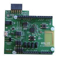
ON Semiconductor RSL10 Manual (37 pages)
Evaluation and Development Board
Brand: ON Semiconductor
|
Category: Motherboard
|
Size: 1 MB
Table of Contents
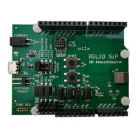
ON Semiconductor RSL10 User Manual (14 pages)
SIP Evaluation and Development Board
Brand: ON Semiconductor
|
Category: Motherboard
|
Size: 0 MB
Table of Contents

ON Semiconductor RSL10 Getting Started (8 pages)
Bluetooth Low Energy chip
Brand: ON Semiconductor
|
Category: Control Unit
|
Size: 0 MB
Table of Contents

ON Semiconductor RSL10 User Manual (14 pages)
Asset Tag
Brand: ON Semiconductor
|
Category: Transceiver
|
Size: 1 MB

ON Semiconductor RSL10 User Manual (14 pages)
USB Dongle
Brand: ON Semiconductor
|
Category: Computer Hardware
|
Size: 3 MB
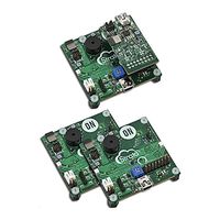
ON Semiconductor RSL10 Getting Started Manual (6 pages)
Mesh Platform
Brand: ON Semiconductor
|
Category: Motherboard
|
Size: 1 MB
Table of Contents
ON Semiconductor RSL10 Getting Started Manual (13 pages)
Smart Shot Camera
Brand: ON Semiconductor
|
Category: Digital Camera
|
Size: 1 MB

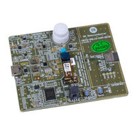
ON Semiconductor RSL10 User Manual (9 pages)
Solar Cell Multi-Sensor Platform
Brand: ON Semiconductor
|
Category: Motherboard
|
Size: 0 MB

ON Semiconductor RSL10 User Manual (4 pages)
Programming
Brand: ON Semiconductor
|
Category: Motherboard
|
Size: 0 MB